Connector Design Guide: From Contact System to Final Assembly
A connector may look like a simple component, but its performance depends on the interaction of multiple engineering elements.
A reliable connector requires careful design of:
- Contact system
- Housing structure
- Locking mechanism
- Sealing system
- Material selection
- Manufacturing process
- Final assembly and testing
A mistake in any stage can affect:
- Electrical performance
- Mechanical reliability
- Environmental protection
- Service life
For engineers developing industrial, automotive, robotics, energy storage, and automation systems, connector design should be considered as a complete engineering process—not just a component selection task.
This guide explains the key stages of connector design, from the internal contact system to final production validation.
Why Connector Design Requires System-Level Thinking
A connector performs three primary functions:
Electrical Connection
Providing stable current or signal transmission.
Important factors:
Contact resistance
Current capacity
Signal integrity
Plating performance
Mechanical Connection
Maintaining a secure connection under real-world conditions.
Important factors:
Mating force
Locking structure
Vibration resistance
Mating cycles
Environmental Protection
Protecting internal components from harsh environments.
Important factors:
Waterproof sealing
Dust protection
Temperature resistance
Chemical exposure
A successful connector design balances all three requirements.
1.Contact System Design: The Core of Connector Performance
The contact system is the electrical heart of a connector.
Its design directly affects:
- Conductivity
- Heat generation
- Reliability
- Service life
Contact Geometry Design
Contact geometry determines how terminals connect and maintain contact force.
Key considerations include:
✔ Contact area
✔ Spring structure
✔ Contact pressure
✔ Current path design
A properly designed contact system provides:
Stable electrical connection
Low resistance
Long-term performance
Contact Material Selection
Common contact materials include:
Copper Alloys
Advantages:
✔ Good conductivity
✔ Balanced strength
✔ Cost efficiency
Phosphor Bronze
Advantages:
✔ Good spring performance
✔ Excellent fatigue resistance
Beryllium Copper
Advantages:
✔ High elasticity
✔ Excellent contact force retention
Used for:
- High-cycle connectors
- Precision applications
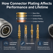
Contact Plating Selection
Surface plating affects:
- Corrosion resistance
- Contact stability
- Mating life
Common options include:
Gold Plating
Advantages:
✔ Excellent corrosion resistance
✔ Reliable low contact resistance
Suitable for:
- Signal connectors
- Medical equipment
- High-cycle applications
Tin Plating
Advantages:
✔ Cost-effective
✔ Suitable for many power applications
The correct plating depends on:
- Current level
- Environment
- Required mating cycles
2.Housing Design: Mechanical Protection and Alignment
The connector housing protects internal contacts and ensures proper mating.
A good housing design must provide:
✔ Mechanical strength
✔ Accurate terminal positioning
✔ Electrical insulation
✔ Assembly efficiency
Housing Material Selection
Common materials include:
PA (Polyamide)
Used for:
- Industrial connectors
- General applications
Benefits:
- Good strength
- Cost efficiency
PBT
Benefits:
- Dimensional stability
- Low moisture absorption
PPS
Benefits:
- High temperature resistance
- Chemical resistance
Material selection depends on:
- Operating temperature
- Mechanical requirements
- Environmental conditions
Terminal Positioning and Polarization
Connector housings should prevent incorrect assembly.
Important design features:
- Keying structures
- Polarization features
- Secondary locks
These features help prevent:
❌ Wrong mating
❌ Terminal back-out
❌ Assembly mistakes
3.Locking Mechanism Design
A reliable locking system prevents accidental disconnection.
Common locking methods include:
Threaded Locking
Advantages:
✔ High vibration resistance
✔ Strong mechanical retention
Applications:
- Industrial equipment
- Outdoor systems
Push-Pull Locking
Advantages:
✔ Fast connection
✔ Easy operation
✔ High mating efficiency
Applications:
- Medical
- Automation
- Test equipment
Snap Locking
Advantages:
✔ Simple operation
✔ Cost-effective
Applications:
- General electronic applications
4.Sealing and Environmental Protection
For harsh environments, sealing design is critical.
Connector sealing protects against:
- Water
- Dust
- Oil
- Humidity
Common sealing components include:
- O-rings
- Gaskets
- Rubber seals
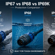
IP Protection Considerations
Depending on the application, connectors may require:
- IP67
- IP68
- IP69K
Higher protection levels require careful control of:
- Seal compression
- Housing interface
- Material compatibility
5.Connector Assembly Design
Connector assembly affects both quality and manufacturing efficiency.
A production-ready design should consider:
Terminal Insertion
Important factors:
✔ Insertion force
✔ Terminal retention
✔ Position accuracy
Secondary Locking System
Secondary locks improve:
- Terminal retention
- Assembly reliability
- Safety
Assembly Error Prevention
Good designs include:
- Visual identification
- Mechanical keying
- Assembly guidance
These features improve production consistency.
6.Connector Validation and Testing
Before mass production, connectors require validation.
Common tests include:
Electrical Testing
Including:
- Contact resistance
- Insulation resistance
- Hi-Pot testing
Mechanical Testing
Including:
- Insertion force
- Extraction force
- Mating cycles
- Vibration testing
Environmental Testing
Including:
- Temperature cycling
- Humidity testing
- Salt spray testing
- Water ingress testing
Testing ensures the connector performs under real application conditions.
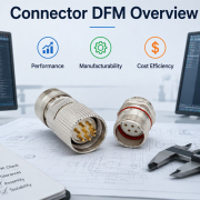
7.Connector Design for Mass Production
A successful connector design must also consider manufacturing.
Key DFM considerations include:
Injection Molding
Evaluate:
- Wall thickness
- Draft angle
- Mold complexity
Terminal Stamping
Evaluate:
- Material utilization
- Contact geometry
- Production consistency
Assembly Automation
Evaluate:
- Assembly direction
- Process repeatability
- Inspection requirements
Good connector design reduces production risks.
How FPIC Approaches Connector Design
FPIC provides customized connector solutions from engineering design through mass production.
Our connector development process considers:
- Contact system design
- Housing structure
- Material selection
- Manufacturing feasibility
- Assembly optimization
- Reliability testing
By combining engineering experience with manufacturing capability, FPIC helps customers develop connectors that meet demanding industrial requirements.
Final Thoughts
Connector design is a system engineering process.
A reliable connector requires the right balance between:
- Contact performance
- Mechanical structure
- Environmental protection
- Manufacturing efficiency
From the first contact design to final assembly validation, every detail influences long-term reliability.
For OEM engineers, selecting the right connector partner means choosing a team that understands both product performance and manufacturing reality.
A high-quality connector is not simply assembled—it is engineered.
FAQ
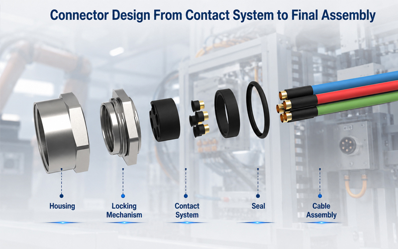
What are the main parts of a connector?
The main parts include contacts, housing, locking mechanism, sealing components, and assembly features.
Why is contact design important in connectors?
The contact system determines electrical performance, contact resistance, current capability, and mating reliability.
What factors affect connector lifetime?
Key factors include materials, contact force, mating cycles, environment, vibration, and manufacturing quality.
What tests are required for connector validation?
Common tests include electrical testing, mechanical testing, environmental testing, and durability testing.
Why should connector design consider manufacturing early?
Early manufacturing consideration improves production efficiency, reduces defects, and controls cost.
Need a Custom Connector Solution?
FPIC develops customized connector solutions for industrial automation, robotics, energy storage, automotive, and other demanding applications.
From contact design and material selection to tooling, assembly, and testing, FPIC supports customers from concept development to mass production.
Contact FPIC today to discuss your connector project.
Resources
- IEC 60512 – Connectors for Electronic Equipment – Tests and Measurements
https://www.iec.ch/
Connector testing methods covering electrical, mechanical, and environmental performance. - IPC/WHMA-A-620 – Requirements and Acceptance for Cable and Wire Harness Assemblies
https://www.ipc.org/
Industry requirements for cable assembly quality and workmanship. - ISO 16750 – Road Vehicles Environmental Conditions and Testing
https://www.iso.org/
Environmental testing guidance for automotive electrical components. - IATF 16949 Automotive Quality Management System
https://www.iatfglobaloversight.org/
Automotive quality management requirements for production consistency.