Automotive Connector Sealing Design: Preventing Water and Dust Failure
Automotive connector operate in environments where water, dust, road spray, mud, cleaning fluids, temperature changes, and mechanical vibration can challenge electrical connection reliability.
A connector may achieve the required ingress protection rating during initial testing but still develop leakage problems if its sealing interfaces are poorly designed, incorrectly assembled, or exposed to conditions beyond the validated operating envelope.
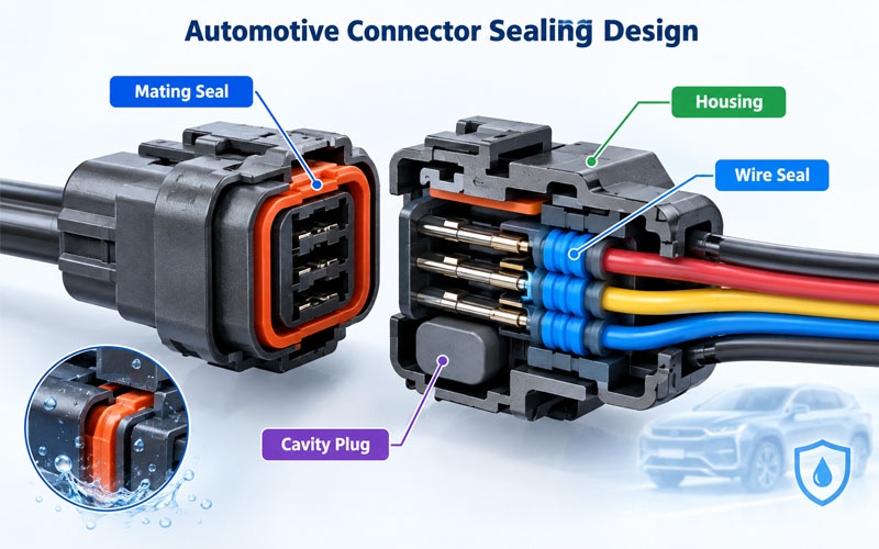
The root cause is not always a defective gasket. Water or dust can enter through several locations, including the mating interface, individual wire seals, unused terminal cavities, rear cable entry, and the connector-to-panel interface.
Effective automotive connector sealing design therefore requires a complete system approach. Engineers must identify every potential ingress path, establish appropriate sealing geometry, control component tolerances, and validate the assembled connector under representative operating conditions.
This article examines the main engineering considerations involved in preventing water and dust ingress in automotive connector systems.
Why Automotive Connector Sealing Matters
Ingress protection helps preserve electrical performance by limiting the entry of foreign solid objects and water into protected areas.
Depending on the application, inadequate sealing may contribute to:
- Corrosion of terminals and conductive surfaces
- Increased contact resistance
- Electrical leakage or reduced insulation resistance
- Intermittent signals and unexpected circuit interruptions
- Contamination of terminal cavities
- Degradation of insulation and sealing materials
- Premature connector replacement and maintenance costs
The severity of these risks depends on the electrical circuit, connector location, exposure conditions, materials, and duration of exposure.
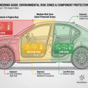
For example, a connector installed in an exposed underbody location may face road spray, dirt, vibration, and temperature cycling. A connector inside a protected passenger compartment may have a different set of environmental requirements.
The sealing strategy should therefore begin with the actual installation environment rather than selecting an IP rating in isolation.
Understanding IP Ratings for Automotive Connectors
The IP Code defined by IEC 60529 classifies the degree of protection provided by enclosures against access to hazardous parts, solid foreign objects, and water ingress. The required rating and test conditions should be selected according to the product specification and intended application. Source: IEC 60529
Two commonly encountered ratings are IP67 and IP68.
IP67
IP67 indicates dust-tight protection at the applicable test conditions and protection against temporary immersion in water under the specified test conditions.
For the standard immersion test associated with IPX7, the conditions include immersion in water for a defined duration and depth. The precise test arrangement depends on the applicable standard and enclosure characteristics.
IP68
IP68 indicates dust-tight protection and protection against continuous immersion under conditions specified for the product. The immersion depth and duration are agreed between the manufacturer and user or defined by the applicable product specification.
IP68 should not automatically be interpreted as providing unlimited immersion capability or superior resistance to every form of water exposure.
Why the Rating Alone Is Not Enough
An IP rating does not automatically demonstrate resistance to every real-world automotive condition, such as:
- High-pressure water jets
- Repeated thermal cycling
- Chemical exposure
- Mechanical vibration
- Cable bending near the seal
- Repeated mating and unmating
- Long-term compression set or material aging
Additional tests may be required to reflect the intended application.
A connector validated for immersion, for example, should not automatically be assumed suitable for high-pressure washing unless the relevant test requirements have also been met.
Identify the Main Water and Dust Ingress Paths
Before selecting sealing components, engineers should map the complete connector assembly and identify its potential leakage paths.
1.Connector Mating Interface
The interface between the male and female connector housings is a common sealing location. A peripheral seal or O-ring may be compressed when the connectors are fully mated.
Potential problems include insufficient compression, seal damage, contamination, housing misalignment, and incomplete mating.
The design must maintain the required sealing condition across the specified dimensional tolerances and operating conditions.
2.Wire-to-Seal Interface
Individual wire seals must fit the actual wire insulation diameter and maintain sealing contact around the cable.
A seal designed for an incorrect wire diameter may produce insufficient interference or excessive deformation.
Cable ovality, surface damage, insulation irregularities, and incorrect wire-seal combinations can also affect performance.
3.Seal-to-Cavity Interface
The outer surface of an individual wire seal must form an effective sealing interface with the terminal cavity.
Potential failure mechanisms include:
- Incorrect seal dimensions
- Damaged sealing lips
- Poor cavity surface quality
- Incomplete terminal insertion
- Seal displacement during assembly
- Incorrect seal retention geometry
The cavity, seal, and terminal should be designed as a compatible system.
4.Unused Terminal Cavities
Unused cavities can create ingress paths if they are not protected according to the connector design.
Appropriate cavity plugs or blanking seals should be used where required. The plug must be compatible with the cavity dimensions, material system, and assembly process.
5.Connector-to-Panel Interface
Panel-mounted connectors may require a face gasket, O-ring, or another sealing feature between the connector body and the mounting surface.
Even when the connector itself is adequately sealed, leakage can occur around the panel interface if the gasket is missing, damaged, incorrectly compressed, or installed against an unsuitable surface.
6.Cable and Harness Routing
Cable routing can influence the mechanical loading applied to the rear sealing interface.
Excessive bending, tension, or repeated movement near the cable entry can disturb the seal or accelerate material wear. Harness support and strain relief should therefore be considered alongside seal geometry.
Seal Compression: The Core of Reliable Sealing Design
Seal compression is one of the most important variables in connector sealing performance.
A seal generally needs sufficient deformation to establish continuous contact pressure against its mating surfaces. However, excessive compression can increase assembly force, damage sealing lips, accelerate material degradation, or cause permanent deformation.
For a simple compression-seal arrangement, nominal compression can be expressed as:
Compression ratio (%) = (Original seal height − Installed seal height) / Original seal height × 100
This relationship is useful for initial design calculations, but it is not a universal acceptance formula for every seal type. Radial seals, axial gaskets, and multi-lip wire seals have different geometric and functional requirements.
Insufficient Compression
If compression is too low, the sealing interface may not maintain adequate contact pressure. Dimensional variation, cable movement, or material shrinkage can then create a leakage path.
Excessive Compression
Overcompression may lead to:
- High connector mating force
- Seal rolling or displacement
- Cut or damaged sealing lips
- Increased compression set
- Housing deformation
- Reduced long-term sealing capability
The appropriate compression range must be established using the seal geometry, material properties, supplier data, dimensional stack-up, and validation results.
Tolerance Stack-Up
The nominal design is only part of the problem. Engineers should evaluate worst-case dimensional combinations involving the housing, seal, cavity, wire, and mating components.
A design that seals correctly at nominal dimensions may fail at a tolerance limit.
Tolerance analysis should therefore include both minimum and maximum sealing interference, as well as the effect of temperature and material aging where relevant.
Preventing Seal Rolling and Displacement
Seal rolling occurs when a seal twists, folds, or moves away from its intended position during assembly or connector mating.
This is a significant design consideration because a displaced seal may create a continuous leakage path even when the connector appears fully assembled.
USCAR-12 includes connector design criteria addressing sealing features, and a 2024 revision notice specifically identified seal rolling as a known failure mode in sealed connector designs. Source: USCAR-12 Revision 6 notice
Design measures should include:
- Appropriate seal-retention geometry
- Controlled lead-in and mating surfaces
- Adequate clearance for seal deformation
- Smooth, continuous sealing surfaces
- Suitable housing alignment features
- Clear assembly instructions and inspection criteria
Seal presence and position should be verifiable where practical. Contrasting seal colors can improve visual inspection when compatible with the product requirements.
Lubricants should only be used when specified or approved for the sealing material and assembly process. An unsuitable lubricant can affect material compatibility or contaminate other interfaces.
Wire Seals and Cable Diameter Control
Single-wire seals are widely used in automotive connectors to seal the interface around individual conductors.
Their performance depends on matching the seal design to the cable construction.
Match the Seal to the Insulation Diameter
The cable’s nominal conductor size is not sufficient for seal selection. The relevant dimension is generally the actual outer diameter of the wire insulation at the sealing interface.
Different insulation materials, wall thicknesses, and manufacturing tolerances can produce different outer diameters for wires with the same nominal conductor cross-section.
Engineers should therefore confirm the permitted insulation-diameter range for the selected seal.
Protect the Sealing Surface During Assembly
Terminal insertion and crimping operations must not cut, tear, or distort the seal.
Potential problems include sharp terminal edges, incorrect tooling, poor alignment, and excessive insertion force.
Production validation should confirm that the selected terminal, seal, wire, and insertion process are compatible.
Evaluate Cable Movement
Wire seals may be exposed to cable bending and movement during installation or vehicle operation.
Where required, testing should evaluate whether the seal maintains its position and sealing function under representative cable loads and movement.
The design should also provide suitable harness support to avoid transferring excessive loads directly to the sealing interface.
Material Selection and Environmental Compatibility
Sealing materials must maintain their required mechanical and chemical properties throughout the intended operating life.
Elastomers such as silicone and other application-specific rubber compounds may be used in automotive connector seals. The correct selection depends on the temperature range, chemical exposure, compression behavior, and mechanical requirements.
Temperature Resistance
Temperature extremes can change material stiffness, elasticity, dimensions, and compression behavior.
A material that performs adequately at room temperature may behave differently after prolonged exposure to high temperature or repeated temperature cycling.
Material selection should therefore consider the complete temperature profile rather than a single maximum temperature value.
Chemical Resistance
Automotive connectors may encounter oils, fuels, cleaning agents, coolants, road contaminants, or other fluids depending on their installation location.
Chemical compatibility should be verified for the actual material and exposure conditions. Generic descriptions such as “oil resistant” should not replace testing against the relevant fluids.
Compression Set and Aging
Compression set describes the tendency of a seal to retain deformation after being compressed for a specified time and under specified conditions.
As a sealing material ages, its ability to recover may decrease. If the remaining contact pressure becomes inadequate, sealing performance may deteriorate.
Material aging, thermal exposure, and long-term compression should be considered in the qualification plan where relevant.
Material Compatibility Across the Assembly
The sealing system includes more than the elastomer. Housing polymers, cable insulation, lubricants, and other components may interact.
The complete material combination should be assessed for dimensional stability, chemical compatibility, and potential degradation.
Housing Geometry and Manufacturing Quality
Even a suitable sealing material cannot compensate for poor housing geometry or uncontrolled manufacturing variation.
Important design and production considerations include:
- Smooth sealing surfaces without damaging flash
- Controlled parting-line placement
- Adequate dimensional accuracy at sealing features
- Stable housing dimensions across production lots
- Appropriate lead-in geometry
- Consistent seal-retention features
- Control of molding defects and surface damage
Molded housing surfaces should be evaluated where the seal contacts them. Flash, burrs, sharp transitions, or surface irregularities may damage the seal or interrupt the sealing path.
For molded components, tool condition and process stability can influence critical dimensions. Inspection plans should identify which features directly affect sealing performance.
Dimensional inspection alone does not prove that a connector is watertight, but it helps maintain the conditions needed for repeatable sealing.
Assembly Process Controls for Sealed Connectors
A robust sealing design requires a repeatable assembly process.
Recommended Process Controls
Component verification: Confirm the correct housing, seal, terminal, wire, and cavity plug.
Incoming inspection: Check critical dimensions and visible seal defects according to the control plan.
Seal installation: Use the specified tooling and assembly sequence.
Terminal insertion: Verify correct terminal seating without damaging the seal.
Connector mating: Confirm full engagement and proper latch operation.
Visual inspection: Check for missing, twisted, displaced, or damaged seals where visible.
Process verification: Use suitable gauges, sensors, or vision systems where required.
Leakage or ingress testing: Apply the specified test method and acceptance criteria.
Traceability: Record relevant inspection and test results according to the quality plan.
Automated assembly can improve repeatability, but automation is only effective when the process can detect the relevant failure modes. For example, a sensor that confirms terminal insertion does not necessarily confirm the condition of every sealing lip.
Inspection methods should therefore be selected based on the specific risk being controlled.
How to Validate Automotive Connector Sealing Performance
Sealing validation should reflect the connector’s intended use, product specification, and customer requirements.
1.Water Ingress Testing
Depending on the required protection level, testing may include immersion, water spray, or other specified exposure methods.
The test setup, duration, pressure, orientation, and acceptance criteria must follow the applicable standard or product specification.
2.Dust Protection Testing
Where dust protection is required, evaluate the assembled connector according to the applicable IP test conditions.
The assessment should reflect the specified protection level rather than assuming that a successful water test also proves dust protection.
3.Pressure or Vacuum Leak Testing
Pressure or vacuum methods may be used to evaluate the sealing capability of suitable connector designs.
The test method must be compatible with the assembly, and the acceptance limit should be established for the product. A leak-rate result should not be interpreted without considering the test configuration and correlation to the required protection level.
4.Thermal Cycling
Temperature cycling can reveal problems caused by differential expansion, material stiffness changes, and seal movement.
Where required, repeat sealing evaluations after thermal exposure to assess whether the assembled system continues to meet its requirements.
5.Vibration and Mechanical Loading
Vibration and mechanical loading may affect seal position, connector mating, and cable entry interfaces.
Testing should use application-relevant conditions and inspect the assembly for seal displacement, housing damage, and electrical degradation.
6.Chemical Exposure
If the connector is expected to encounter automotive fluids, expose representative samples to the specified fluids and conditions.
After exposure, evaluate the relevant material properties and sealing performance according to the validation plan.
7.Post-Test Inspection
After testing, inspect for water or dust ingress, seal displacement, housing cracks, terminal corrosion, and other signs of degradation.
Where electrical reliability is critical, include the specified continuity, insulation resistance, or other electrical checks before and after environmental testing.
A connector’s sealing performance should be evaluated as part of the complete assembly, including its mating counterpart, wires, plugs, and mounting interfaces where applicable.
Common Automotive Connector Sealing Failures and Solutions
| Failure symptom | Potential root cause | Recommended engineering action |
|---|---|---|
| Water enters at the mating interface | Insufficient compression, incomplete mating, or damaged peripheral seal | Review seal geometry, tolerance stack-up, and mating controls |
| Leakage around a wire | Incorrect wire diameter, seal damage, or inadequate interference | Verify wire and seal compatibility and assembly tooling |
| Seal rolls during mating | Inadequate retention, unsuitable lead-in, or excessive friction | Review seal-retention and mating geometry |
| Leakage at unused cavities | Missing or incompatible cavity plug | Verify cavity-plug selection and presence |
| Leakage around a panel-mounted connector | Damaged gasket, poor mounting surface, or incorrect compression | Review mounting interface and installation torque where specified |
| Sealing deteriorates after temperature cycling | Material aging, compression set, or dimensional changes | Reassess material selection and environmental validation |
| Inconsistent results between production lots | Dimensional variation, material variation, or process instability | Strengthen critical-dimension and process controls |
| Leakage after cable movement | Excessive cable loading or seal displacement | Improve harness support and validate cable movement conditions |
These symptoms are diagnostic starting points rather than proof of a single root cause. Failure analysis should inspect the actual leakage path and correlate it with dimensional, material, assembly, and test evidence.
How to Build a Practical Sealing Validation Plan
A useful validation plan links each sealing risk to a design requirement, verification method, and acceptance criterion.
| Design risk | Verification approach | Expected evidence |
|---|---|---|
| Inadequate seal compression | Dimensional analysis and design verification | Confirmed compression or interference range |
| Seal displacement | Assembly evaluation and seal-retention testing | Seal remains in the intended position |
| Water ingress | Applicable immersion or water-exposure test | Meets specified ingress acceptance criteria |
| Dust ingress | Applicable dust test | Meets the required solid-particle protection level |
| Material degradation | Temperature and chemical exposure | No unacceptable deterioration against product requirements |
| Cable-entry leakage | Wire-seal compatibility and assembled-system testing | Required sealing performance is maintained |
| Production variation | Dimensional inspection and process monitoring | Critical features remain within specified limits |
Testing should be selected according to the connector design and intended application. Not every product requires every test listed above, and passing one test does not automatically demonstrate compliance with all ingress-protection or durability requirements.
For automotive programs, applicable customer specifications and connector performance requirements should determine the final validation sequence.
How FPIC Supports Automotive Connector Development
Automotive connector sealing requires coordinated engineering across housing design, terminal interfaces, cable entry, materials, manufacturing tolerances, and validation.
FPIC supports automotive connector projects through connector development, manufacturing quality control, electrical testing, and reliability validation. For customized connector applications, early review of installation conditions, sealing interfaces, cable dimensions, and required environmental tests can help identify potential design risks before tooling and mass production.
The goal is to develop a sealing solution that meets the specified protection level while remaining practical to assemble, inspect, and maintain throughout its intended service life.
Final Thoughts
Reliable automotive connector sealing depends on the entire assembly—not simply the presence of a rubber seal or an IP rating.
Seal compression, mating geometry, wire dimensions, material compatibility, housing quality, and assembly controls all influence whether a connector can maintain its required protection against water and dust.
The most effective approach is to identify every potential ingress path, control the relevant design parameters, and validate the complete assembly under conditions representative of its intended application.
By integrating sealing design with manufacturing controls and environmental testing, engineers can reduce the risk of ingress-related failures and improve long-term automotive connector reliability.
FAQ
What causes water ingress in automotive connectors?
Common causes include damaged or displaced seals, insufficient compression, incorrect wire-seal combinations, incomplete connector mating, missing cavity plugs, and leakage around mounting interfaces. Environmental aging and manufacturing variation can also contribute.
What is the difference between IP67 and IP68 automotive connectors?
Both ratings include dust-tight protection under the applicable IP test conditions. IP67 covers temporary immersion under specified conditions, while IP68 covers continuous immersion under conditions defined for the product. Neither rating automatically establishes resistance to every type of water jet, chemical exposure, or long-term mechanical stress.
How does seal compression affect connector waterproofing?
Insufficient compression may leave a leakage path, while excessive compression can damage the seal, increase mating force, or accelerate material degradation. The appropriate range depends on seal geometry, material properties, tolerances, and validation results.
Which materials are used for automotive connector seals?
Silicone and other application-specific elastomers are commonly used. Selection depends on operating temperature, fluid exposure, compression behavior, mechanical requirements, and compatibility with the wire insulation and connector housing.
Why can a connector fail a water ingress test after thermal cycling?
Temperature changes can alter material stiffness and dimensions, while prolonged exposure can contribute to compression set or seal displacement. Thermal cycling may therefore reveal weaknesses that are not apparent during initial testing.
Does an IP67 rating guarantee protection against high-pressure washing?
No. IP67 describes protection under its specified test conditions and does not automatically establish resistance to high-pressure water jets. Additional testing should be performed if high-pressure washing is part of the intended operating environment.
How can manufacturers improve automotive connector sealing consistency?
Key measures include controlling critical dimensions, matching seals to actual wire diameters, preventing seal damage during assembly, verifying connector engagement, monitoring production variation, and applying the specified ingress tests and acceptance criteria.
Developing a customized automotive connector for demanding environmental conditions?
Discuss your sealing requirements, connector configuration, cable dimensions, and validation needs with FPIC. Early engineering review can help identify potential ingress paths and align connector design with manufacturing and application requirements.
Contact FPIC to discuss your automotive connector project.
Resources
- International Electrotechnical Commission (IEC) – IEC 60529: Degrees of Protection Provided by Enclosures (IP Code)
The official standard covering IP classification for protection against solid foreign objects and water ingress.
https://webstore.iec.ch/en/publication/2452 - United States Council for Automotive Research (USCAR) – USCAR-12 Connector Design Criteria
Automotive connector design criteria covering connector seals, retention features, and other design-review considerations.
https://saemobilus.sae.org/standards/uscar12-4-electrical-connector-design-criteria - USCAR – USCAR-12 Revision 6 Sealing Design Update
A revision notice highlighting measurable seal-design requirements and the risk of seal rolling in sealed connector systems.
https://uscar.org/download/162/uscar-12-connector-design/13907/rev12-6-9.pdf - TE Connectivity – Automotive Seals and Cavity Plugs
Manufacturer technical information on single-wire seals, cavity plugs, seal-to-wire interfaces, and seal-to-cavity interfaces.
https://www.te.com/en/products/automotive-parts/automotive-connector-accessories/automotive-seals-cavity-plugs.html - SAE International – USCAR-2: Performance Specification for Automotive Electrical Connector Systems
Automotive connector performance-testing reference covering applicable electrical connector systems and their validation requirements.
https://saemobilus.sae.org/standards/uscar2-8-performance-specification-automotive-electrical-connector-systems