How Automotive Connector Terminals Improve Electrical Reliability
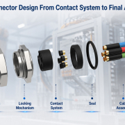
In an automotive connector system, the plastic housing provides structure and protection, but the terminal creates the electrical connection.
This makes the terminal one of the most important components for electrical reliability.
A connector may have a robust housing, reliable locking mechanism, and effective sealing system, but poor terminal design can still result in:
- High contact resistance
- Localized heating
- Intermittent electrical signals
- Voltage drop
- Fretting corrosion
- Terminal deformation
- Electrical discontinuity
- Premature connector failure
The challenge becomes even greater in modern vehicles, where electrical systems must operate under higher current loads, tighter packaging constraints, vibration, temperature variation, and increasingly demanding reliability requirements.
For this reason, automotive terminal design should not be treated simply as a metal component selection problem.
It is a system involving:
Terminal Geometry + Contact Force + Material + Plating + Crimping + Retention + Thermal Behavior + Manufacturing Control
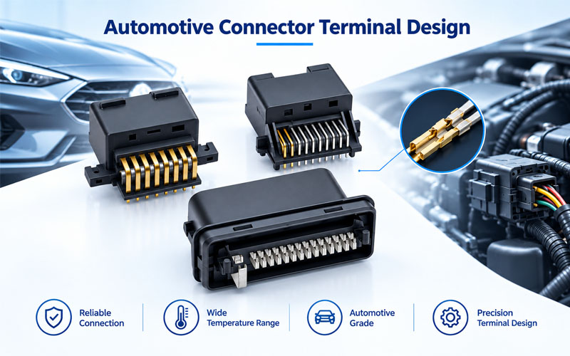
1.Why Automotive Connector Terminals Matter
The terminal is the conductive path between the wire and the mating connector.
A simplified current path is:
Wire → Crimp Area → Terminal Body → Contact Interface → Mating Terminal → Electrical Circuit
Every interface in this path contributes to overall electrical performance.
A weak point anywhere in the current path can increase resistance or create instability.
For example:
- Poor crimping can increase wire-to-terminal resistance.
- Insufficient contact force can increase contact resistance.
- Damaged plating can expose the base material.
- Terminal deformation can reduce contact area.
- Poor retention can cause terminal movement.
- Excessive current can increase terminal temperature.
Therefore, automotive electrical reliability begins with controlling the complete terminal system.
2.Contact Force Is Fundamental to Electrical Reliability
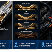
When two metal contacts mate, the surfaces are not perfectly flat at the microscopic level.
Actual electrical conduction occurs through localized contact points.
Contact force helps maintain stable physical contact between the mating surfaces.
If contact force is too low, the terminal may become more sensitive to:
- Vibration
- Thermal expansion
- Fretting
- Surface contamination
- Oxidation
- Mechanical movement
As the contact interface becomes less stable, electrical resistance can increase.
But higher force is not always better
Excessive contact force can create other problems:
- Higher mating force
- Difficult assembly
- Increased terminal wear
- Deformation
- Reduced serviceability
The design objective is therefore controlled and stable contact force, not simply maximum contact force.
3.Terminal Geometry Controls the Contact Interface
Terminal geometry directly influences how the mating contacts interact.
Depending on the terminal system, engineers may optimize:
- Contact beam geometry
- Contact point location
- Contact length
- Beam thickness
- Spring characteristics
- Contact angle
- Terminal stiffness
- Contact normal force
- Mating alignment
A well-designed contact system should maintain sufficient contact force while accommodating manufacturing tolerances and service conditions.
Multi-point contact
Some terminal architectures use multiple contact points to improve electrical redundancy.
If one microscopic contact area experiences contamination or surface degradation, other contact areas can help maintain the electrical path.
This can be particularly useful in applications exposed to vibration or environmental stress.
4.Terminal Material Affects Current Carrying and Reliability
Terminal materials must provide an appropriate combination of:
- Electrical conductivity
- Mechanical strength
- Spring properties
- Formability
- Corrosion resistance
- Thermal stability
- Manufacturing compatibility
Copper-based alloys are widely used in electrical terminals because they provide a useful balance between conductivity and mechanical properties.
However, the specific alloy should be selected according to the terminal design and application requirements.
A terminal carrying substantial current must also manage heat generation.
The relationship between electrical power and resistance is:
P = I²R
As current increases, even a relatively small resistance can generate significant heat.
This makes material selection particularly important for higher-current automotive applications.
5.Plating Protects the Contact Interface
Terminal plating is used to improve the stability and durability of the contact surface.
Common plating systems may include:
- Tin
- Nickel
- Gold
- Silver
The appropriate plating depends on the electrical, mechanical, environmental, and cost requirements of the application.
Tin plating
Tin is widely used for automotive terminals because of its practical balance of cost, conductivity, solderability, and corrosion protection.
However, tin contact systems require appropriate contact design because surface films can influence electrical performance.
Gold plating
Gold provides excellent corrosion resistance and stable electrical contact characteristics.
It may be selected for applications requiring high reliability or specific environmental performance, although cost and application requirements must be considered.
Silver plating
Silver offers excellent electrical conductivity and can be useful in certain higher-current applications, subject to the environmental and design requirements.
The important point is that plating should be designed together with the contact system, rather than selected independently.
6.Contact Resistance Depends on the Entire Terminal System
Automotive connector contact resistance is influenced by multiple factors.
These include:
- Contact force
- Contact geometry
- Contact area
- Surface condition
- Plating
- Crimp quality
- Temperature
- Vibration
- Contamination
- Corrosion
- Mating cycles
This means that a terminal cannot be considered reliable simply because its initial resistance is low.
A stronger design objective is:
Maintain stable contact resistance throughout the expected service life.
This is particularly important when connectors are exposed to vibration, thermal cycling, moisture, or high current.
7.Crimp Quality Directly Affects Electrical Performance
The mating interface is only one part of the electrical path.
The connection between the wire and terminal is equally important.
A properly designed crimp creates a mechanically stable and electrically conductive connection between the conductor and terminal.
Poor crimping can cause:
- Increased electrical resistance
- Localized heating
- Wire pull-out
- Intermittent electrical connection
- Conductor damage
- Long-term fatigue
Important crimp characteristics can include:
- Crimp height
- Crimp width
- Conductor insertion
- Terminal position
- Pull-out force
- Crimp geometry
- Cross-section condition
For automotive production, crimp quality should be controlled as a manufacturing process rather than inspected only at the end.
8.Terminal Retention Prevents Electrical Instability
The terminal must remain correctly positioned inside the connector housing.
A terminal that moves backward during mating or vehicle operation can reduce the effective contact interface.
This can cause:
- Incomplete mating
- Reduced contact force
- Intermittent signals
- Increased contact resistance
- Circuit interruption
Terminal retention features therefore contribute indirectly but significantly to electrical reliability.
Common retention concepts include:
- Primary terminal locks
- Secondary terminal locks
- TPA systems
- Housing retention features
The terminal and housing must be designed as a complete system.
9.TPA and CPA Support Reliable Terminal Positioning
Two commonly used automotive connector features are TPA and CPA.
TPA — Terminal Position Assurance
TPA helps confirm that terminals are correctly seated and helps prevent terminal movement.
It can provide a secondary level of terminal retention after insertion.
CPA — Connector Position Assurance
CPA helps verify that the connector is fully mated and locked.
It can reduce the risk of incomplete mating caused by:
- Partial insertion
- Misalignment
- Assembly error
- Vibration-related disengagement
These features are particularly valuable in automotive manufacturing, where assembly accuracy and field reliability are closely connected.
10.Fretting and Vibration Can Degrade Terminal Performance
Automotive connectors can experience continuous vibration.
Small relative movements at the contact interface can produce fretting.
Over time, fretting can contribute to:
- Surface wear
- Oxide formation
- Plating damage
- Increased contact resistance
- Intermittent electrical behavior
Terminal design can help reduce these risks through:
- Stable contact force
- Appropriate contact geometry
- Suitable plating
- Controlled mechanical movement
- Robust connector retention
- Proper cable strain relief
Vibration validation should therefore evaluate both mechanical integrity and electrical stability.
11.Thermal Performance Matters for High-Current Terminals
Higher current creates greater thermal challenges.
Using:
P = I²R
doubling current results in four times the resistive power at the same resistance.
For example, if a terminal interface has:
- 1 mΩ resistance at 50 A → 2.5 W
- 1 mΩ resistance at 100 A → 10 W
- 2 mΩ resistance at 100 A → 20 W
This illustrates why resistance control becomes increasingly important as current increases.
Excessive temperature can accelerate:
- Material degradation
- Contact force loss
- Oxidation
- Plating deterioration
- Housing deformation
Therefore, high-current terminal design requires consideration of both electrical and thermal performance.
12.Terminal Geometry Must Consider Current Distribution
Current does not always distribute uniformly across a terminal.
Localized current concentration can increase temperature in specific regions.
Engineers may need to evaluate:
- Conductor cross-section
- Terminal thickness
- Contact geometry
- Current path length
- Contact area
- Crimp transition
- Thermal dissipation
- Housing constraints
For high-current applications, the terminal should be evaluated as part of the complete electrical and thermal system.
Simply increasing terminal size is not always the optimal solution.
13.Terminal Tolerances Affect Electrical Reliability
Automotive terminals are manufactured at high volumes, which means dimensional variation must be controlled.
Critical dimensions can include:
- Contact beam geometry
- Terminal width
- Terminal thickness
- Crimp dimensions
- Locking features
- Mating interface
- Position within the housing
Excessive dimensional variation can affect:
- Contact force
- Mating force
- Terminal retention
- Electrical resistance
- Connector assembly
This is why tooling capability and process control are essential for stable terminal performance.
14.Terminal Manufacturing Quality Is as Important as Design
A good terminal design can still fail if manufacturing variation is not controlled.
Automotive terminal production may involve:
Stamping → Forming → Plating → Inspection → Crimping → Assembly → Electrical Testing
Each stage can affect final performance.
Stamping and forming
Poor forming can change the contact geometry or spring characteristics.
Plating
Plating thickness, coverage, adhesion, and surface condition can influence contact durability.
Crimping
Incorrect crimp dimensions can increase electrical resistance or reduce mechanical strength.
Assembly
Incorrect terminal insertion or incomplete locking can result in terminal back-out.
Therefore, terminal reliability depends on both engineering design and process capability.
15.How Automotive Connector Terminals Are Validated
Terminal validation should cover both initial performance and performance after stress exposure.
Typical evaluation areas include:
Electrical
- Contact resistance
- Voltage drop
- Insulation resistance where applicable
- Current carrying capability
- Electrical continuity
Mechanical
- Terminal retention
- Mating and unmating force
- Crimp pull force
- Terminal insertion force
- Mating-cycle durability
Environmental
- Temperature cycling
- High-temperature exposure
- Humidity
- Corrosion
- Chemical exposure
- Water or sealing-related testing where applicable
Dynamic reliability
- Vibration
- Mechanical shock
- Intermittent electrical monitoring
The exact test program should be based on the applicable automotive standard, customer specification, connector architecture, and vehicle installation environment.
16.Initial Performance Is Not Enough
One of the most important principles in automotive terminal validation is to evaluate performance retention.
A terminal may initially demonstrate:
- Low contact resistance
- Good retention
- Stable mating force
- Good plating condition
But after environmental and mechanical exposure, performance may change.
For this reason, engineers should compare:
Initial Condition → Stress Exposure → Final Condition
Key parameters may include:
- Contact resistance
- Contact force
- Mating force
- Terminal retention
- Visual condition
- Plating condition
- Crimp integrity
The change between initial and final measurements can provide valuable information about degradation mechanisms.
17.Common Automotive Terminal Failure Modes
| Failure Mode | Possible Cause | Electrical Impact |
|---|---|---|
| High contact resistance | Low contact force / surface degradation | Voltage drop and heating |
| Terminal back-out | Weak retention / incomplete insertion | Intermittent or open circuit |
| Fretting | Vibration / micro-motion | Resistance instability |
| Crimp failure | Incorrect crimp geometry | Increased resistance / wire separation |
| Plating wear | Excessive mating / poor material selection | Corrosion and resistance increase |
| Terminal deformation | Excessive mechanical load | Poor contact engagement |
| Corrosion | Moisture / contamination | Increased resistance |
| Thermal degradation | Excessive current / resistance | Further electrical degradation |
| Contact fatigue | Repeated mechanical stress | Loss of stable electrical connection |
Failure analysis should identify the underlying mechanism rather than only the visible symptom.
18.Designing Terminals for Long-Term Electrical Reliability
A reliable automotive terminal design should consider several factors simultaneously.
1.Optimize contact force
Maintain sufficient force throughout the intended service life.
2.Select the right material
Balance conductivity, strength, formability, corrosion resistance, and thermal requirements.
3.Match the plating to the application
Consider current, environment, mating cycles, and required reliability.
4.Control crimp geometry
Ensure stable electrical and mechanical connection between wire and terminal.
5.Control terminal position
Use appropriate retention and secondary locking features.
6.Manage vibration
Minimize harmful relative movement at the contact interface.
7.Evaluate thermal behavior
Consider current, resistance, heat generation, and heat dissipation.
8.Validate after environmental stress
Measure performance before and after relevant reliability tests.
This integrated approach is more effective than optimizing any single parameter independently.
19.Automotive Terminal Reliability and Global Standards
Terminal validation may need to align with standards and customer requirements such as:
- LV214
- USCAR-2
- ISO 16750
- Customer-specific OEM specifications
- Terminal and crimp specifications
These standards should not simply be treated as interchangeable checklists.
The actual validation plan should identify:
- Applicable standard revision
- Connector configuration
- Terminal type
- Test method
- Test severity
- Sample quantity
- Acceptance criteria
- Customer-specific requirements
For example, LV214 and USCAR-2 have overlapping automotive connector reliability objectives but belong to different qualification frameworks. The applicable requirements should therefore be mapped before formal testing begins.
How FPIC Supports Automotive Connector Terminal Reliability
Automotive connector reliability depends heavily on terminal engineering and manufacturing consistency.
FPIC supports automotive connector projects with capabilities covering connector development, terminal processing, automated inspection, electrical testing, assembly, and mass production.
For automotive applications, engineering teams can evaluate terminal geometry, contact performance, crimp quality, retention, electrical characteristics, and production requirements as part of the complete connector system.
Automotive connector production can also incorporate inspection and testing processes designed to control critical characteristics from terminal manufacturing through final assembly.
The objective is to connect:
Terminal Design → Material & Plating → Crimping → Assembly → Electrical Testing → Reliability Validation → Mass Production
This helps ensure that terminal performance is not only strong during initial testing but also consistent across production.
Final Thoughts
Automotive connector terminals are at the heart of electrical reliability.
Their performance depends on far more than conductivity alone. Contact force, terminal geometry, material, plating, crimp quality, retention, vibration resistance, thermal behavior, and manufacturing control all influence the stability of the electrical connection.
A reliable terminal should maintain a stable electrical interface throughout its expected service life—not simply achieve a low initial contact resistance.
By combining robust terminal design with controlled manufacturing, electrical testing, mechanical validation, and environmental reliability testing, automotive connector manufacturers can reduce electrical failure risks and build more dependable connector systems.
FAQ
What is the most important factor in automotive connector terminal reliability?
There is no single factor. Contact force, terminal geometry, plating, material, crimp quality, retention, vibration resistance, and thermal behavior all contribute to reliability.
How does terminal contact force affect electrical performance?
Adequate contact force helps maintain stable physical contact between mating surfaces. Insufficient force can increase sensitivity to vibration, fretting, contamination, and surface degradation.
Why is terminal plating important?
Plating protects the contact interface and influences corrosion resistance, wear behavior, and electrical stability. The appropriate plating depends on the application, current, environment, mating cycles, and reliability requirements.
How does crimp quality affect connector reliability?
The crimp forms the electrical and mechanical connection between the wire and terminal. Poor crimp geometry can increase resistance, generate heat, reduce mechanical strength, and cause intermittent electrical failures.
What is the role of TPA in automotive connectors?
TPA, or Terminal Position Assurance, helps confirm that terminals are properly seated and provides additional protection against terminal movement within the connector housing.
Why is terminal retention important?
If a terminal moves backward during mating or vehicle operation, the contact interface may become unstable. This can cause increased resistance, intermittent signals, or circuit interruption.
How are automotive connector terminals validated?
Validation can include contact resistance, crimp pull force, terminal retention, mating cycles, vibration, temperature cycling, humidity, corrosion, chemical exposure, and other application-specific tests.
Are automotive terminal tests the same for every connector?
No. The test plan depends on the connector architecture, terminal type, electrical load, vehicle installation position, environmental conditions, customer requirements, and applicable standards such as LV214 or USCAR-2.
Developing a custom automotive connector or terminal?
FPIC supports automotive connector projects from terminal and connector design through prototyping, electrical testing, reliability validation, and mass production.
Contact our engineering team to discuss your terminal requirements, current rating, crimp configuration, plating, validation plan, and production needs.
Resources
- SAE International – USCAR2-9: Performance Specification for Automotive Electrical Connector Systems
Official SAE specification covering performance testing requirements for automotive electrical connector systems.
SAE USCAR2-9 - ISO – ISO 16750 Road Vehicles: Environmental Conditions and Testing
International standard series covering environmental conditions and testing for electrical and electronic equipment in road vehicles.
ISO 16750 - USCAR – Automotive Connector Testing Resources
Industry resources related to automotive electrical connector performance and validation.
USCAR - TE Connectivity – Automotive Terminals and Connector Systems
Technical and product information covering automotive terminals, connectors, contact systems, and related technologies.
TE Connectivity Automotive Solutions