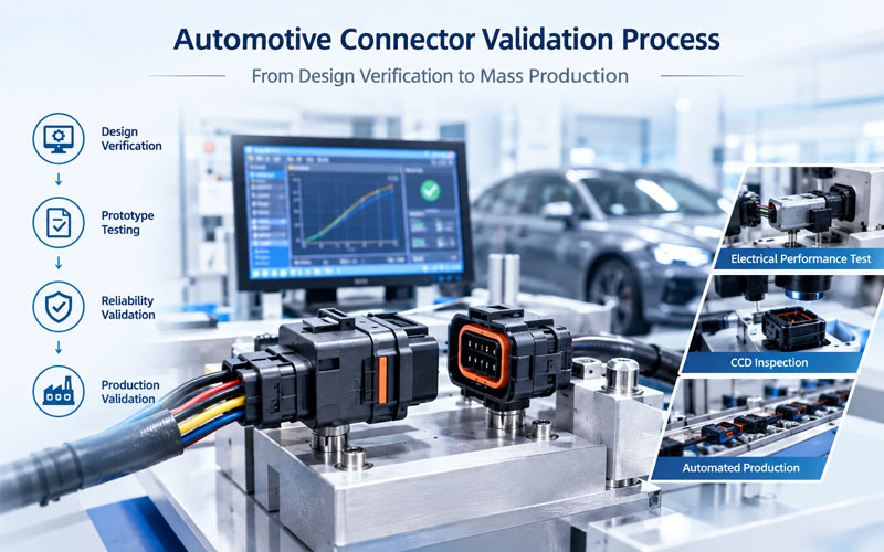
Automotive Connector Validation Process: From Design Verification to Mass Production
An automotive connector must perform reliably throughout the vehicle’s service life while being exposed to vibration, temperature variation, moisture, chemicals, mating cycles, mechanical loads, and electrical stress.
For this reason, connector validation cannot be treated as a single final inspection step. It is a staged engineering process that begins with design requirements and continues through prototype verification, reliability testing, manufacturing validation, and mass-production control.
The objective is not simply to demonstrate that one connector sample works. The objective is to establish evidence that the design is suitable, the manufacturing process is capable, and the production connector will consistently meet defined requirements.
Automotive connector validation commonly involves customer-specific specifications together with applicable industry and vehicle standards. For example, ISO 16750 provides environmental testing frameworks for road-vehicle electrical and electronic components, while SAE/USCAR specifications are used for particular connector and terminal validation requirements. The exact validation matrix should always be based on the customer’s drawing, specification, application, and mounting environment.
1.Automotive Connector Validation Starts With Design Requirements
Before testing begins, engineers need to establish exactly what the connector is expected to withstand.
Typical requirements include:
- Rated voltage and current
- Contact resistance
- Insulation resistance
- Dielectric withstand voltage
- Number of circuits
- Terminal size and contact system
- Mating and unmating force
- Terminal retention force
- Connector locking force
- CPA and TPA requirements
- Sealing and IP protection requirements
- Operating temperature range
- Vibration and mechanical loads
- Thermal cycling requirements
- Humidity and water exposure
- Chemical resistance
- Mating-cycle requirements
- Packaging and transportation requirements
- Dimensional and tolerance requirements
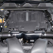
The connector’s installation position is particularly important. A connector mounted inside a protected passenger compartment does not necessarily experience the same environmental stresses as one located in an engine compartment, underbody area, door, battery system, or other exposed location.
ISO 16750-3:2023 addresses mechanical loads, while ISO 16750-4:2023 addresses climatic loads for road-vehicle electrical and electronic equipment. These standards emphasize that environmental requirements should be related to the component’s specific vehicle mounting conditions.
Key question at this stage
The engineering team should be able to answer:
What failure modes must this connector prevent during its intended service life?
This question becomes the foundation for the validation plan.
2.Design Verification: Check the Connector Before Formal Reliability Testing
Design verification is intended to confirm that the physical connector design satisfies its engineering requirements before significant resources are invested in full validation.
Typical design verification activities include:
Dimensional verification
Critical dimensions should be measured against the released drawing.
Important characteristics may include:
- Terminal cavity dimensions
- Connector mating interface
- Terminal positioning
- CPA and TPA dimensions
- Seal dimensions
- Mounting features
- Polarization features
- Locking structures
- Keying geometry
Dimensional variation can directly affect terminal retention, mating performance, sealing, and assembly compatibility.
Material verification
Engineers may verify:
- Housing material
- Terminal base material
- Plating system
- Seal material
- CPA/TPA material
- Temperature capability
- Chemical compatibility
Material selection should be considered together with the actual application environment rather than evaluated independently.
Mechanical design verification
Mechanical checks can include:
- Mating force
- Unmating force
- Terminal insertion force
- Terminal retention
- Connector retention
- Lock engagement
- CPA engagement
- TPA engagement
- Housing strength
These tests help identify weaknesses in the connector architecture before environmental validation begins.
3.Prototype Validation: Confirm the Design With Representative Samples
Once the design has passed initial verification, representative prototypes can be used for more comprehensive testing.
Prototype samples should reflect the intended production design as closely as possible.
This includes:
- Final or production-intent materials
- Production-intent terminals
- Production-intent plating
- Representative seals
- Representative molding conditions
- Correct assembly configuration
Testing an early prototype made from temporary materials may provide useful engineering information, but it should not automatically be treated as production validation evidence.
Why production-intent samples matter
Connector performance can be influenced by:
- Resin shrinkage
- Molding parameters
- Terminal forming
- Plating thickness
- Crimp geometry
- Seal compression
- Assembly variation
Therefore, validation should progressively move toward samples produced using the same materials, tooling concepts, processes, and controls expected in mass production.
4.Electrical Validation
Electrical validation confirms that the connector can maintain safe and stable electrical performance.
Common electrical tests include:
Contact resistance
Low and stable contact resistance is important because resistance generates heat under current load.
The basic relationship is:
P = I²R
Even a small increase in resistance can create additional localized heating in high-current applications.
Contact resistance should therefore be evaluated both initially and after applicable environmental or mechanical stresses.
Insulation resistance
Insulation resistance testing evaluates whether adequate electrical isolation exists between conductive circuits and other specified points.
This becomes particularly important for connectors exposed to:
- Moisture
- Contamination
- High temperature
- Thermal cycling
- Aging
- High voltage
Dielectric withstand voltage
Dielectric withstand testing evaluates the connector’s ability to withstand a specified voltage without electrical breakdown.
The actual test voltage, duration, configuration, and acceptance criteria should be defined by the applicable customer and product specification.
Continuity and intermittent monitoring
For connectors exposed to vibration or mechanical movement, continuous electrical monitoring during mechanical testing can help identify intermittent contact events that may not be visible during a simple pre-test and post-test resistance measurement.
5.Mechanical Validation
Automotive connectors must remain mechanically stable after repeated mating and exposure to vehicle loads.
Typical mechanical validation may include:
Mating and unmating force
Excessive mating force can create assembly problems, while insufficient retention or locking force can increase the risk of incomplete engagement.
The target is a controlled interface that supports reliable assembly and serviceability.
Terminal retention
Terminal retention testing verifies that terminals remain properly positioned within the connector housing.
Terminal back-out can cause:
- Intermittent electrical connection
- Increased contact resistance
- Incomplete mating
- Circuit interruption
Connector retention
The complete connector may also need to remain securely mounted to a mating component, bracket, module, or vehicle structure.
Vibration and mechanical loads
Automotive connectors can experience continuous vibration and mechanical loads throughout vehicle operation.
ISO 16750-3:2023 specifically addresses mechanical loads for road-vehicle electrical and electronic equipment.
Validation should consider the actual mounting condition, connector orientation, cable loading, and expected vehicle environment.
6.Environmental Validation
Environmental validation is where many connector design weaknesses become visible.
Automotive connectors may encounter:
- High and low temperatures
- Rapid temperature changes
- Humidity
- Water exposure
- Salt contamination
- Dust
- Automotive fluids
- Vibration
- Mechanical shock
ISO 16750-4:2023 addresses climatic loads for road-vehicle electrical and electronic equipment, while ISO 16750-2:2023 addresses electrical loads.
Temperature cycling
Thermal cycling can create repeated expansion and contraction of:
- Housing materials
- Terminals
- Seals
- Plated surfaces
- Mating interfaces
Differences in material expansion can gradually affect contact force, sealing, and dimensional stability.
Humidity and water exposure
Moisture can contribute to:
- Corrosion
- Leakage current
- Insulation degradation
- Contact resistance increase
For sealed connectors, validation should consider both the sealing system and the mechanical interface.
Chemical exposure
Depending on the application, connectors may be exposed to substances such as:
- Engine fluids
- Cleaning agents
- Fuel-related contaminants
- Salt
- Coolants
- Oils and lubricants
The exact chemical test conditions should follow the applicable customer specification.
7.Connector Sealing and Water Ingress Validation
For sealed automotive connectors, environmental protection depends on the entire sealing architecture rather than the housing alone.
Important elements include:
- Interface seals
- Wire seals
- Cable diameter compatibility
- Seal compression
- Housing tolerances
- Terminal cavity geometry
- Connector locking
- Assembly condition
A connector may pass a basic sealing test initially but experience leakage after thermal cycling, vibration, or repeated mating.
Therefore, sealing validation should be considered as part of the complete reliability sequence.
A practical validation principle
Instead of asking only:
Does the connector pass the water-ingress test?
Engineers should also ask:
Does the connector maintain its sealing performance after the mechanical and environmental stresses expected during service?
This distinction is important for long-term reliability.
8.Validation After Environmental Stress
Post-test inspection is just as important as the environmental test itself.
After a test sequence, engineers may evaluate:
- Contact resistance
- Insulation resistance
- Dielectric withstand
- Terminal retention
- Mating force
- Seal condition
- Housing deformation
- Terminal plating
- Corrosion
- Cracking
- Discoloration
- Terminal displacement
The purpose is to identify both immediate failures and degradation trends.
For example, a connector that still functions after thermal cycling but shows a significant increase in contact resistance may require further engineering investigation.
9.Reliability Validation Should Reflect Real Failure Mechanisms
A strong validation plan is not simply a long list of tests.
Each test should have a reason.
For example:
| Potential Failure Mode | Relevant Validation Focus |
|---|---|
| Contact resistance increase | Electrical resistance measurement |
| Terminal back-out | Terminal retention and mechanical testing |
| Fretting | Vibration and electrical monitoring |
| Housing cracking | Mechanical and thermal stress |
| Water ingress | Sealing and environmental testing |
| Corrosion | Humidity, salt and chemical exposure |
| Lock failure | Mating, retention and mechanical testing |
| Seal degradation | Temperature and environmental exposure |
| Insulation breakdown | IR and dielectric withstand testing |
This approach makes validation more efficient because the test plan is connected directly to identified risks.
10.DFMEA and Validation Should Be Connected
Design Failure Mode and Effects Analysis (DFMEA) can help engineers identify potential failure modes before testing begins.
For an automotive connector, DFMEA considerations may include:
- Contact system
- Terminal geometry
- Housing structure
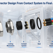
- Locking mechanism
- CPA/TPA
- Sealing system
- Material selection
- Plating
- Mounting features
- Cable interface
- Assembly orientation
The validation plan should then address the significant risks identified during design analysis.
This creates a closed engineering loop:
Requirement → Design → DFMEA → Validation Plan → Testing → Failure Analysis → Design Improvement → Revalidation
This process is more effective than waiting for a final validation test to reveal a design weakness.
11.From Design Validation to Manufacturing Validation
Passing design validation does not automatically mean that the connector is ready for mass production.
The manufacturing process must also be validated.
Typical manufacturing considerations include:
- Injection molding capability
- Terminal stamping and forming
- Plating control
- Crimping process
- Terminal insertion
- Seal installation
- Connector assembly
- Automated inspection
- Electrical testing
- Dimensional inspection
- Traceability
The objective is to demonstrate that the production process can repeatedly manufacture connectors that meet the validated design requirements.
12.Process Validation Before Mass Production
Manufacturing validation should focus on process capability and repeatability.
Typical controls may include:
Incoming material control
Verify critical materials and components before production.
Tooling control
Injection molds and stamping tools should maintain critical dimensions throughout production.
Crimp process control
For connector assemblies involving wires and terminals, crimp quality is critical.
Possible controls include:
- Crimp height
- Crimp width
- Pull force
- Cross-section analysis
- Terminal position
- Conductor insertion
Automated inspection
Depending on product complexity, production may use:
- CCD vision inspection
- Dimensional inspection
- Terminal position detection
- Electrical continuity testing
- Functional testing
Traceability
Production traceability can connect:
Raw Material → Process Lot → Tooling → Machine → Operator/Station → Inspection Data → Finished Product
This becomes especially important when supplying automotive customers.
13.Pilot Production and Production Validation
Before full-scale mass production, a pilot or production-validation run can help confirm that the manufacturing process performs under realistic production conditions.
The objective is to verify:
- Production cycle stability
- Assembly consistency
- Inspection capability
- Yield
- Process capability
- Packaging
- Labeling
- Traceability
- Operator workflow
- Quality control points
The samples from this stage should represent the actual production process as closely as possible.
A successful engineering prototype does not necessarily guarantee stable mass production. Production validation closes this gap.
14.PPAP and Customer Approval
For many automotive programs, production approval involves structured documentation and customer-specific requirements.
Depending on the customer and program, documentation may include:
- Design records
- Engineering change documentation
- Process flow
- PFMEA
- Control plan
- Measurement system analysis
- Dimensional results
- Material and performance results
- Initial sample inspection
- Process capability evidence
- Packaging specifications
- Sample parts
- Customer-specific documents
PPAP requirements vary by customer and program, so the exact submission package should be aligned with the applicable customer requirements.
The key objective is to demonstrate that the supplier understands the product requirements and has established a controlled process for producing conforming parts.
15.Mass Production Control Must Continue After Validation
Validation is not the end of quality management.
Once the connector enters mass production, the manufacturer must maintain control over the characteristics that were validated.
Important production controls may include:
- Incoming inspection
- First-piece inspection
- In-process inspection
- Automated electrical testing
- Visual inspection
- Dimensional monitoring
- Crimp monitoring
- Plating control
- Process capability monitoring
- Lot traceability
- Final inspection
- Periodic reliability testing
Process changes should also be managed carefully.
Changes involving materials, tooling, terminal geometry, plating, sealing components, or manufacturing parameters may require engineering review and potentially additional validation.
16.A Practical Automotive Connector Validation Flow
A complete validation process can be structured as follows:
1.Customer Requirements
↓
2.Application and Environmental Analysis
↓
3.Connector Design
↓
4.DFMEA and Risk Analysis
↓
5.Design Verification
↓
6.Prototype Testing
↓
7.Electrical, Mechanical and Environmental Validation
↓
8.Failure Analysis and Design Improvement
↓
9.Production-Intent Samples
↓
10.Manufacturing Process Validation
↓
11.Pilot Production
↓
12.PPAP / Customer Approval
↓
13.Mass Production
↓
14.Ongoing Quality and Change Control
This structure helps connect engineering development with manufacturing readiness.
17.Common Automotive Connector Validation Mistakes
Mistake 1: Testing too late
If reliability testing begins only after the design is finalized, failures may result in expensive redesign and schedule delays.
Better approach: connect DFMEA and validation planning to the early design stage.
Mistake 2: Validating only electrical performance
A connector may pass electrical testing while still having mechanical or environmental weaknesses.
Better approach: combine electrical, mechanical, climatic, sealing, and material-related validation.
Mistake 3: Using non-representative samples
Prototype samples made with temporary materials or processes may not accurately represent production performance.
Better approach: progressively transition toward production-intent samples.
Mistake 4: Ignoring post-test measurements
A pass/fail result alone may hide degradation.
Better approach: compare key parameters before and after environmental and mechanical testing.
Mistake 5: Treating validation as the end of quality control
A validated design can still experience production variation.
Better approach: connect product validation with process validation and ongoing production controls.
18.What a Strong Validation Report Should Demonstrate
A useful automotive connector validation report should clearly connect requirements, test conditions, results, and conclusions.
A typical structure includes:
| Section | Purpose |
|---|---|
| Product identification | Defines the exact connector configuration |
| Applicable requirements | Establishes acceptance criteria |
| Sample information | Identifies samples and production status |
| Test method | Defines how the test was performed |
| Test conditions | Records temperature, load, duration and other parameters |
| Initial results | Establishes baseline performance |
| Stress exposure | Records environmental or mechanical conditions |
| Final results | Shows post-test performance |
| Visual inspection | Identifies physical degradation |
| Failure analysis | Explains any abnormal result |
| Corrective action | Documents engineering response |
| Final conclusion | Confirms validation status |
Good documentation makes validation results traceable and easier to review during customer approval and future engineering changes.
How FPIC Supports Automotive Connector Development
For automotive connector projects, validation should be considered together with design, manufacturing, and quality control.
FPIC supports automotive connector development from prototype and engineering verification through production, with automotive manufacturing experience and quality systems designed for demanding applications.
Its automotive connector capabilities include connector development, terminal processing, automated inspection, electrical testing, and production quality control. For projects requiring customer-specific validation, the test plan can be aligned with the applicable drawings, specifications, environmental conditions, and reliability requirements.
The goal is to establish a clear engineering path from:
Customer Requirement → Connector Design → Validation → Process Verification → Mass Production
This approach helps reduce late-stage design changes and supports more consistent production performance.
Final Thoughts
Automotive connector validation is not a single laboratory test. It is a staged process that begins with requirements and design verification and continues through reliability testing, manufacturing validation, customer approval, and mass-production control.
The most effective validation strategies connect each test to a specific failure mechanism and use representative samples to verify both product performance and process capability.
By integrating DFMEA, electrical testing, mechanical validation, environmental testing, production-intent samples, process controls, and ongoing quality management, automotive connector manufacturers can build a stronger technical foundation for reliable mass production.
FAQ
What is automotive connector validation?
Automotive connector validation is the process of verifying that a connector meets defined electrical, mechanical, environmental, reliability, and manufacturing requirements before and during production release.
What tests are commonly included in automotive connector validation?
Depending on the application, testing may include contact resistance, insulation resistance, dielectric withstand, mating force, terminal retention, vibration, temperature cycling, humidity, water ingress, corrosion, chemical exposure, and mating-cycle testing.
What is the difference between design verification and validation?
Design verification checks whether the connector design meets specified engineering requirements. Validation typically provides broader evidence that the product performs as intended under representative application and environmental conditions.
Why is production-intent sampling important?
Production-intent samples better represent the materials, tooling, processes, and assembly conditions expected during mass production, making the validation results more representative.
Is ISO 16750 sufficient for automotive connector validation?
Not necessarily. ISO 16750 provides environmental and electrical/mechanical testing frameworks for road-vehicle electrical and electronic equipment, but connector validation may also require customer-specific specifications and connector or terminal standards. The applicable validation matrix should be defined for the specific product and application.
When should connector validation begin?
Validation planning should begin during the design stage. Requirements, DFMEA, failure modes, and intended vehicle environment should be considered before formal reliability testing begins.
Developing a custom automotive connector?
FPIC can support automotive connector projects from design and prototype development to testing, process verification, and mass production. Contact our engineering team to discuss connector requirements, validation plans, environmental conditions, and production needs.
Resources
- ISO 16750-2:2023 – Electrical Loads
International standard covering electrical loads and related test requirements for electrical and electronic equipment in road vehicles.
ISO 16750-2:2023 - ISO 16750-3:2023 – Mechanical Loads
Provides requirements and test guidance related to mechanical loads for road-vehicle electrical and electronic equipment.
ISO 16750-3:2023 - ISO 16750-4:2023 – Climatic Loads
Covers climatic loads and related testing considerations for vehicle electrical and electronic equipment.
ISO 16750-4:2023 - USCAR-2 – Performance Specification for Automotive Electrical Connector Systems
Provides an automotive connector validation framework covering new connector designs and related validation requirements.
USCAR-2 Connector Testing Specification