Tag Archive for: Connector Engineering

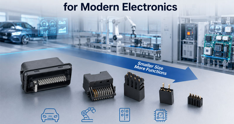
Connector Miniaturizationfor Modern Electronics

Modern electronic systems are becoming smaller, lighter, and more integrated.

Devices that once had plenty of internal space now need to accommodate more functions within increasingly compact packages.

This trend has created strong demand for smaller and higher-density connectors.

However, making a connector smaller is not simply a matter of reducing the housing dimensions.

As connector size decreases, the available space for contacts, insulation, mechanical structures, sealing, and assembly also becomes smaller.

At the same time, electrical and mechanical requirements often remain the same—or become more demanding.

Connector miniaturization therefore requires a careful balance between:

Size + Electrical Performance + Mechanical Reliability + Manufacturability

For applications such as automotive electronics, industrial automation, medical equipment, consumer electronics, robotics, and compact control systems, successful miniaturization requires engineering optimization at every stage.

Connector Miniaturizationfor Modern Electronics


What Is Connector Miniaturization?

Connector miniaturization refers to reducing the physical size, pitch, height, or overall footprint of a connector while maintaining its required functional performance.

Miniaturization may involve:

  • Smaller housing dimensions
  • Reduced contact pitch
  • Smaller terminals
  • Lower connector height
  • Higher contact density
  • Reduced mounting footprint

The goal is usually to achieve:

More electrical functionality in less physical space.

However, reducing dimensions can create new engineering constraints.


Why Are Connectors Becoming Smaller?

Several market trends are driving connector miniaturization.

Smaller Electronic Devices

Electronic products increasingly require:

  • Compact control units
  • Smaller sensors
  • Reduced PCB size
  • Higher functional density

Connectors must fit within these increasingly constrained spaces.


Higher Functional Integration

A single electronic module may now integrate:

  • Power
  • Data
  • Sensors
  • Control signals
  • Communication interfaces

This increases the number of electrical connections required within the same physical space.


Weight Reduction

In automotive and portable equipment, reducing component size can also contribute to overall weight reduction.

Smaller connectors can help optimize:

  • Wiring space
  • Module dimensions
  • Packaging
  • System weight

1.Contact Pitch Becomes More Challenging

One of the biggest challenges in connector miniaturization is reducing contact pitch.

As the distance between contacts decreases, engineers must maintain sufficient:

  • Electrical isolation
  • Mechanical strength
  • Positioning accuracy
  • Insulation performance

A smaller pitch leaves less room for dimensional variation.

This makes:

Terminal Position + Housing Accuracy + Manufacturing Tolerance

increasingly important.


2.Electrical Clearance Becomes More Limited

When contacts are positioned closer together, the available electrical spacing decreases.

Engineers need to evaluate:

  • Clearance
  • Creepage
  • Insulation thickness
  • Working voltage
  • Pollution environment

For higher-voltage applications, simply reducing contact spacing may not be possible without changing the connector architecture.

This creates a fundamental design challenge:

How can the connector become smaller without compromising electrical safety?


3.Current Density Can Increase

Miniaturization can also increase current density.

If the same current must pass through a smaller terminal, the available conductive cross-section may decrease.

This can increase:

  • Current density
  • Joule heating
  • Contact temperature
  • Thermal stress

The design must therefore balance:

Contact Size + Material Conductivity + Contact Resistance + Current Rating

A smaller connector is not automatically suitable for the same current level as a larger connector.


4.Thermal Management Becomes More Difficult

Heat generated at a connector contact must be transferred away from the contact interface.

When connector dimensions decrease:

  • Thermal paths may become smaller
  • Contact spacing may decrease
  • Heat concentration can increase
  • Cooling space may be reduced

This can become particularly important in:

  • High-current applications
  • Compact automotive modules
  • Industrial control systems
  • Power electronics

Thermal design should therefore be considered alongside electrical design.


5.Contact Spring Design Becomes More Sensitive

Smaller terminals have less physical space for spring structures.

However, the contact still needs sufficient force to maintain reliable electrical connection.

The challenge becomes:

Small Contact + Controlled Spring Force + Long-Term Reliability

If spring force is too low:

  • Contact resistance may increase
  • Vibration resistance may decrease
  • Intermittent connections may occur

If spring force is too high:

  • Mating force increases
  • Contact wear may accelerate
  • Mating cycle life may decrease

Miniaturization therefore requires highly controlled contact geometry.


6.Mechanical Strength Can Be Reduced

Reducing terminal and housing dimensions can reduce structural strength.

Miniature connectors may be more sensitive to:

  • Insertion force
  • Extraction force
  • Cable pulling
  • Side loading
  • Vibration
  • Shock

The housing must therefore maintain sufficient:

  • Retention strength
  • Locking performance
  • Terminal support
  • Mechanical stability

Miniaturization should never compromise the mechanical integrity of the connector.


7.Manufacturing Tolerances Become More Critical

As components become smaller, the same absolute dimensional variation represents a larger percentage of the total geometry.

For example, a small terminal-position variation may have little effect in a large connector but become significant in a fine-pitch connector.

Critical areas include:

  • Terminal pitch
  • Terminal position
  • Housing cavities
  • Locking features
  • Contact geometry
  • Seal interfaces

This makes precision manufacturing and tolerance control increasingly important.


8.Assembly Becomes More Difficult

Smaller connector components can be more challenging to assemble.

Potential problems include:

  • Terminal misalignment
  • Incomplete terminal insertion
  • Seal damage
  • Housing deformation
  • Locking errors

Manual assembly becomes more difficult as component size decreases.

For high-volume production, manufacturers may need:

  • Precision assembly fixtures
  • Automated insertion
  • Vision inspection
  • Automated electrical testing

9.Inspection Becomes More Challenging

Miniaturized features may be difficult to inspect using conventional measurement methods.

Traditional tools may not provide sufficient resolution or repeatability.

Manufacturers may therefore use:

  • Optical inspection
  • CCD systems
  • Microscopic inspection
  • Coordinate measurement
  • Automated dimensional analysis

Inspection strategies must be designed around the actual critical features of the connector.


10.Miniaturization Can Affect Mating Reliability

Smaller connectors may have less mechanical tolerance for misalignment.

During mating, even a small angular or positional deviation can influence:

  • Insertion force
  • Terminal engagement
  • Contact wipe
  • Housing alignment

Good guiding features become increasingly important.

Common design solutions include:

  • Polarization keys
  • Guide posts
  • Chamfered mating surfaces
  • Self-alignment structures

These features help reduce the risk of incorrect or incomplete mating.


11.Sealing Becomes More Difficult

For miniature waterproof connectors, the available space for seals is limited.

Yet the connector may still need to achieve:

  • IP67
  • IP68
  • Other application-specific sealing requirements

Engineers must optimize:

  • Seal geometry
  • Compression
  • Housing interfaces
  • Cable diameter
  • Material selection

Reducing the connector size without compromising sealing performance can be challenging.


12.Miniaturization and Mating Cycles

A smaller connector does not necessarily have a shorter mating life, but reducing contact dimensions can make wear management more difficult.

Each mating cycle may affect:

  • Contact plating
  • Spring structure
  • Contact surface
  • Housing alignment

For applications requiring frequent connection and disconnection, engineers should validate:

  • Insertion force
  • Extraction force
  • Contact resistance
  • Wear
  • Mating cycle performance

13.Material Selection Becomes More Important

Material selection can become more critical as connector dimensions decrease.

The housing material must provide appropriate:

  • Mechanical strength
  • Dimensional stability
  • Temperature resistance
  • Electrical insulation

Contact materials must provide:

  • Conductivity
  • Elasticity
  • Fatigue resistance
  • Corrosion resistance

For miniature connectors, small changes in material performance can have a noticeable impact on the overall system.


14.Miniaturization Requires Better Thermal and Electrical Simulation

For advanced connector designs, simulation can help evaluate potential problems before tooling.

Depending on the application, engineers may evaluate:

Electrical

  • Current density
  • Voltage distribution
  • Contact resistance

Thermal

  • Temperature rise
  • Heat concentration
  • Thermal paths

Mechanical

  • Contact deformation
  • Stress distribution
  • Mating force

Simulation does not replace physical testing, but it can help identify design risks earlier.


Miniaturization Trade-Offs

Connector miniaturization is fundamentally an optimization problem.

Design GoalPotential Challenge
Smaller housingLess internal space
Higher contact densityReduced spacing
Higher currentGreater heat generation
Lower mating forcePotentially lower contact force
Smaller terminalsReduced mechanical strength
Smaller sealsMore difficult sealing
Tight tolerancesHigher manufacturing cost
More featuresMore complex assembly

The objective is not simply:

Make It Smaller.

The objective is:

Make It Smaller Without Losing Performance.


Application Considerations

Different applications have different miniaturization priorities.

ApplicationKey Miniaturization Challenge
Automotive ElectronicsSpace, vibration, temperature
Medical EquipmentCompactness, reliability, cleanliness
Industrial AutomationDensity, mechanical durability
RoboticsSize, movement, mating cycles
Consumer ElectronicsSpace and high-density interconnection
SensorsCompact size and environmental protection
Control ModulesDensity, thermal management, assembly

How to Approach Miniature Connector Design

A successful miniature connector development process should include:

Step 1: Define the Application

Identify:

  • Voltage
  • Current
  • Signal type
  • Temperature
  • Vibration
  • Mating cycles
  • Environmental exposure

Step 2: Establish the Size Target

Define:

  • Maximum housing dimensions
  • Contact pitch
  • Mounting footprint
  • Connector height

Step 3: Design the Contact System

Optimize:

  • Contact geometry
  • Spring force
  • Contact material
  • Plating
  • Current capacity

Step 4: Analyze Thermal and Electrical Performance

Evaluate:

  • Contact resistance
  • Temperature rise
  • Current density
  • Clearance
  • Creepage

Step 5: Perform Tolerance Analysis

Review:

  • Terminal position
  • Housing dimensions
  • Mating alignment
  • Locking features
  • Seal interfaces

Step 6: Validate Through Testing

Typical validation can include:

  • Contact resistance
  • Temperature rise
  • Insertion/extraction force
  • Mating cycles
  • Vibration
  • Thermal cycling
  • Environmental testing

Common Connector Miniaturization Mistakes

MistakePotential Result
Reducing size without thermal analysisExcessive temperature rise
Reducing contact pitch excessivelyElectrical clearance problems
Undersized terminalHigher current density
Insufficient spring forceUnstable contact
Excessive spring forceHigh mating force
Ignoring tolerance stack-upMating problems
Weak housing structureMechanical failure
Poor seal designWater or dust ingress
Insufficient inspectionManufacturing variation

How FPIC Supports Connector Miniaturization

FPIC supports customized connector development with engineering capabilities covering:

✔ Contact system design

✔ Housing design

✔ Terminal stamping

✔ Precision injection molding

✔ Tolerance control

✔ Electrical testing

✔ Mechanical reliability testing

✔ CCD/visual inspection

✔ Automated assembly and packaging

For demanding automotive applications, FPIC’s connector manufacturing capabilities are supported by IATF 16949 quality management requirements.

Connector production can also incorporate controlled cleanliness practices aligned with VDA 19.1 / ISO 16232 requirements where applicable.

The engineering objective is to optimize connector size without sacrificing:

  • Electrical performance
  • Mechanical reliability
  • Manufacturing consistency
  • Service life

Final Thoughts

Connector miniaturization is one of the most important trends in modern electronics.

But reducing connector dimensions creates a chain of engineering challenges.

Smaller connectors require careful control of:

Contact Density + Electrical Clearance + Thermal Performance + Spring Force + Mechanical Strength + Manufacturing Tolerance

The best miniature connector is not simply the smallest possible connector.

It is the smallest connector that can reliably meet its electrical, mechanical, environmental, manufacturing, and lifecycle requirements.

Successful miniaturization therefore requires a system-level approach:

Define → Design → Simulate → Manufacture → Test → Validate

When size reduction is combined with disciplined engineering and manufacturing control, miniature connectors can deliver high-density performance without compromising reliability.


FAQ

What is connector miniaturization?

Connector miniaturization is the process of reducing connector size, contact pitch, height, or mounting footprint while maintaining required electrical and mechanical performance.

What is the biggest challenge in miniature connector design?

There is no single challenge. Contact density, electrical clearance, thermal management, mechanical strength, manufacturing tolerance, and assembly precision often become more difficult simultaneously.

Does a smaller connector support less current?

Not necessarily, but reducing terminal size and conductive area can increase current density and heat generation. Current capability must be evaluated based on the complete contact design and application conditions.

Why are manufacturing tolerances important for miniature connectors?

As connector features become smaller, the same dimensional variation can have a greater functional impact, especially on terminal alignment, mating, and contact performance.

How can miniature connectors maintain reliability?

Reliable miniature connectors require optimized contact geometry, suitable materials and plating, controlled tolerances, appropriate thermal design, precise manufacturing, and application-specific validation.


Need a Compact Connector for a Space-Constrained Application?

FPIC supports custom connector development from contact design and tooling through precision manufacturing, testing, and mass production.

Whether you need compact signal connectors, circular connectors, automotive connectors, or customized high-density solutions, our engineering team can help balance size, performance, reliability, and manufacturability.

Contact FPIC to discuss your miniature connector requirements.


Resources

  1. IEC 60512 – Connectors for Electronic Equipment – Tests and Measurements
    https://www.iec.ch/
    International testing framework for electrical and mechanical performance of connectors.
  2. USCAR Standards
    https://www.uscar.org/
    Automotive connector performance and validation resources.
  3. IPC Standards
    https://www.ipc.org/
    Industry standards and technical resources for electronic interconnection and manufacturing.
  4. IATF 16949
    https://www.iatfglobaloversight.org/
    Automotive quality management requirements for organizations in the automotive supply chain.
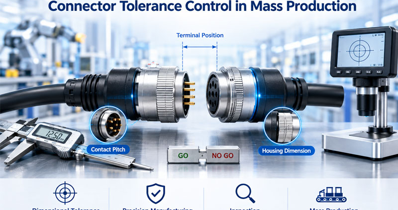
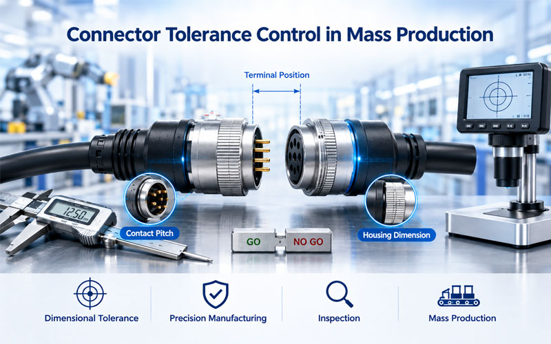
Connector Tolerance Control in Mass Production

A connector can meet its nominal drawing dimensions and still create problems during mass production if dimensional tolerances are not properly controlled.

Connector performance depends on multiple components working together:

  • Housing
  • Terminals
  • Seals
  • Locks
  • Contact interfaces
  • Mating features

Each component has its own dimensional variation.

When these variations accumulate, the final assembly can behave differently from the nominal design.

This is why tolerance control is not simply a drawing requirement.

It is a critical part of connector manufacturing quality.

Poor tolerance control can result in:

  • Difficult mating
  • Excessive insertion force
  • Loose connections
  • Contact instability
  • Seal leakage
  • Assembly interference
  • Poor interchangeability
  • Increased production scrap

For automotive, industrial, medical, energy storage, and other demanding applications, controlling dimensional variation from design through mass production is essential for consistent field performance.

Connector Tolerance Control in Mass Production


What Is Connector Tolerance Control?

Tolerance control defines the acceptable dimensional variation of connector components and ensures that manufacturing processes remain within those limits.

Typical controlled dimensions include:

  • Terminal position
  • Contact pitch
  • Housing dimensions
  • Locking features
  • Connector alignment
  • Seal compression
  • Mounting dimensions
  • Mating interfaces

For example, a connector may have a nominal terminal position specified on the drawing.

During manufacturing, the actual position will naturally vary within a defined tolerance.

The engineering challenge is ensuring that this variation does not negatively affect:

Mating + Electrical Contact + Mechanical Retention + Sealing


Why Nominal Dimensions Are Not Enough

One common mistake is designing around nominal dimensions without considering actual manufacturing variation.

Suppose two mating connector components each have dimensional tolerances.

Even if both are individually within specification, their combined variation may produce:

  • Excessive interference
  • Excessive clearance
  • Misalignment
  • Increased insertion force

This is known as tolerance stack-up.

Mass production makes this issue especially important because thousands or millions of parts may be produced.

A small dimensional issue that occurs only occasionally can become a significant quality problem at production scale.


1.Tolerance Stack-Up Can Affect Mating Performance

Connector mating requires several features to align correctly.

For example:

Housing → Guide Feature → Terminal → Contact Interface

Each feature contributes to the final position.

If multiple tolerances shift in the same direction, the accumulated variation can become significant.

Potential consequences include:

  • Difficult mating
  • Excessive insertion force
  • Connector misalignment
  • Terminal deformation
  • Housing interference

Engineers should therefore evaluate tolerance stack-up during the design phase.


2.Terminal Position Tolerance Is Critical

Terminal position directly affects electrical and mechanical performance.

If terminals are not positioned consistently:

  • Contact alignment may change
  • Mating force may vary
  • Contact wipe may become inconsistent
  • Adjacent terminals may have reduced clearance

This becomes particularly important for:

  • High-density connectors
  • Fine-pitch connectors
  • Multi-pin automotive connectors
  • Signal connectors

Precise terminal positioning helps maintain consistent contact behavior across production lots.


3.Housing Tolerance Affects Alignment

The connector housing provides the mechanical framework for the terminal system.

Important dimensions can include:

  • Terminal cavities
  • Guide rails
  • Keying features
  • Locking structures
  • Mating interfaces
  • Mounting holes

If housing dimensions vary excessively, the terminal system may not remain in the intended position.

This can affect:

  • Mating accuracy
  • Contact alignment
  • Connector retention
  • Assembly consistency

4.Contact Tolerance Affects Electrical Reliability

Electrical performance depends on stable contact geometry.

Small dimensional changes can influence:

  • Contact force
  • Contact area
  • Contact wipe
  • Contact resistance

For example, if a terminal beam is slightly outside its intended geometry, the resulting spring force may differ from the design target.

This can create variation in electrical performance between individual connectors.

Therefore:

Dimensional Control → Contact Geometry → Contact Force → Electrical Reliability


5.Seal Tolerance Affects Waterproofing

For sealed connectors, dimensional tolerance becomes even more important.

Sealing performance depends on controlled compression between:

  • Seal
  • Housing
  • Cable
  • Mating connector

Insufficient compression may cause leakage.

Excessive compression may cause:

  • High insertion force
  • Seal deformation
  • Assembly difficulty
  • Premature seal wear

Proper tolerance analysis helps ensure that the sealing system remains within its intended operating range.

This is especially important for:

  • Automotive connectors
  • Outdoor equipment
  • Industrial machinery
  • Agricultural equipment
  • IP67/IP68 applications

6.Locking Features Require Consistent Tolerances

Connector locks need to provide reliable retention while remaining practical for assembly and service.

If the locking geometry is inconsistent:

Too Tight

The operator may experience:

  • Difficult locking
  • High assembly force
  • Component deformation

Too Loose

Potential problems include:

  • Insufficient retention
  • Connector separation
  • Poor vibration resistance

Tolerance control helps maintain the intended balance between retention force and usability.


7.Tolerance Control Improves Assembly Consistency

Mass production requires thousands of assemblies to behave similarly.

If connector dimensions vary too much, operators may encounter:

  • Different insertion forces
  • Different locking forces
  • Different terminal positions
  • Different connector fit

This can increase:

  • Assembly time
  • Rework
  • Scrap
  • Production complaints

Consistent dimensional control improves manufacturing repeatability.


8.Tolerance Control Supports Interchangeability

OEM customers often expect components manufactured at different times to remain interchangeable.

For example:

  • Connector A from Lot 1
  • Connector B from Lot 2

should still mate correctly when both comply with the approved design.

This requires consistent control of critical dimensions.

Interchangeability is particularly important for:

  • Service replacement
  • Global manufacturing
  • Multiple production lines
  • Multiple suppliers

9.Critical-to-Function Dimensions Need More Attention

Not every connector dimension has the same impact on performance.

A practical approach is to identify:

Critical Dimensions

Dimensions directly affecting:

  • Contact performance
  • Mating
  • Sealing
  • Retention
  • Safety

Important Dimensions

Dimensions affecting:

  • Assembly
  • Positioning
  • Manufacturing consistency

General Dimensions

Dimensions with relatively low functional impact.

This allows engineering and quality teams to focus measurement resources where they create the greatest value.


10.Statistical Process Control Helps Maintain Tolerance

Mass production requires more than checking finished parts.

Manufacturing processes should be monitored continuously.

Common methods include:

  • SPC
  • Process capability analysis
  • Control charts
  • Sampling inspection
  • Automated dimensional inspection

Two commonly discussed capability indicators are:

Cp

and

Cpk

These help evaluate whether a manufacturing process can consistently produce parts within specification.

The specific acceptance criteria should be defined according to the product, drawing requirements, customer standards, and quality plan.


11.Measurement Equipment Matters

Tolerance control is only meaningful when measurement systems are appropriate.

Depending on the feature, manufacturers may use:

  • Calipers
  • Micrometers
  • Height gauges
  • Coordinate measuring machines
  • Optical measurement systems
  • Vision inspection
  • Go/No-Go gauges

For high-volume connector production, automated optical inspection can help monitor dimensional features efficiently.

Measurement systems should also be properly calibrated and maintained.


12.Mold and Stamping Processes Affect Connector Tolerances

Connector mass production often involves multiple manufacturing processes.

Injection Molding

Housing dimensions can be affected by:

  • Material shrinkage
  • Mold condition
  • Processing temperature
  • Injection parameters
  • Cooling conditions

Terminal Stamping

Terminal geometry can be influenced by:

  • Tool wear
  • Material thickness
  • Stamping accuracy
  • Progressive die condition

Assembly

Final connector dimensions can also be affected by:

  • Terminal insertion
  • Seal installation
  • Locking components
  • Assembly fixtures

Tolerance control therefore requires coordination across the entire manufacturing process.


13.Design for Manufacturability Starts With Tolerance Analysis

Tolerance control should begin before mass production.

During DFM review, engineers should ask:

  • Which dimensions are function-critical?
  • Which tolerances are realistically manufacturable?
  • Where can tolerance stack-up occur?
  • Which dimensions require automated inspection?
  • Can the process maintain the required capability?
  • Are overly tight tolerances adding unnecessary cost?

An unnecessarily tight tolerance can increase:

  • Tooling cost
  • Inspection requirements
  • Production cycle time
  • Scrap rate

The goal is not to make every dimension extremely precise.

The goal is to apply the right tolerance to the right feature.


14.Tolerance Control and Cost

Tolerance and cost are closely related.

In general, tighter tolerances may require:

  • More precise tooling
  • More process control
  • More inspection
  • Higher manufacturing cost

However, loose tolerances can create:

  • Higher defect rates
  • Assembly problems
  • Field failures
  • Customer complaints

Therefore, effective tolerance design balances:

Performance + Manufacturability + Cost

This is one of the most important principles of connector DFM.


Connector Tolerance Control Example

Consider a multi-pin connector with:

  • Housing
  • Terminals
  • Seals
  • Locking mechanism

The final mating condition depends on multiple dimensions.

A simplified tolerance chain might be:

Housing Position

Terminal Position

Contact Alignment

Contact Force

Electrical Reliability

If any critical dimension is poorly controlled, the final performance can shift.

This illustrates why connector tolerance control must be treated as a system-level engineering issue.


Common Connector Tolerance Control Mistakes

MistakePotential Result
Designing only around nominal dimensionsUnexpected production variation
Ignoring tolerance stack-upMating problems
Overly tight tolerancesHigher cost and scrap
Loose terminal positioningContact instability
Poor seal tolerance controlLeakage
Insufficient process monitoringLot-to-lot variation
Inadequate measurement systemsUndetected dimensional problems
Ignoring tooling wearGradual dimensional drift

Connector Tolerance Control Checklist

Before releasing a connector for mass production, engineering and quality teams should review:

Design

✔ Are critical dimensions identified?

✔ Has tolerance stack-up been analyzed?

✔ Are tolerances function-based?

Tooling

✔ Can the mold maintain the required dimensions?

✔ Is stamping-tool wear monitored?

Manufacturing

✔ Are critical dimensions measured?

✔ Are process parameters controlled?

✔ Is SPC applied where appropriate?

Assembly

✔ Are terminal positions consistent?

✔ Are seals correctly installed?

✔ Are locking features functioning consistently?

Validation

✔ Is mating force within the intended range?

✔ Is contact resistance stable?

✔ Is sealing performance validated?

✔ Is interchangeability verified?


How FPIC Controls Connector Quality in Mass Production

FPIC applies engineering and manufacturing controls throughout connector production.

Quality management can include:

✔ Dimensional inspection

✔ Terminal position control

✔ Injection molding process control

✔ Stamping process monitoring

✔ Assembly verification

✔ Electrical testing

✔ Visual inspection

✔ Reliability validation

For automotive connector production, FPIC operates under IATF 16949 quality requirements and applies controlled manufacturing processes to support consistent product performance.

For customers requiring demanding cleanliness requirements, mass production can also be managed in accordance with VDA 19.1 / ISO 16232 practices where applicable.

The objective is not simply to produce connectors within drawing dimensions.

It is to maintain consistent performance across production batches.


Final Thoughts

Connector tolerance control is one of the foundations of reliable mass production.

A connector is a system of interacting components, and small dimensional variations can influence:

  • Mating
  • Contact force
  • Contact resistance
  • Sealing
  • Retention
  • Assembly consistency
  • Interchangeability

Effective tolerance engineering does not mean making every dimension as tight as possible.

It means identifying the dimensions that matter most and controlling them with the right manufacturing and inspection methods.

The best connector designs balance:

Function + Tolerance + Process Capability + Cost

When these elements are aligned from the beginning, manufacturers can achieve more consistent production and OEM customers can gain greater confidence in connector performance.


FAQ

Why is tolerance control important in connector manufacturing?

Tolerance control ensures that connector components consistently fit, mate, seal, and maintain electrical performance throughout mass production.

What is connector tolerance stack-up?

Tolerance stack-up is the cumulative effect of dimensional variations from multiple components or features that contribute to a final functional dimension.

Does tighter tolerance always mean better connector quality?

No. Excessively tight tolerances can increase manufacturing cost and scrap without providing additional functional benefits. Tolerances should be based on actual performance requirements.

Which connector dimensions are most critical?

Terminal position, contact geometry, mating features, locking structures, sealing interfaces, and other dimensions directly affecting electrical, mechanical, or sealing performance are typically critical.

How is connector dimensional tolerance controlled during mass production?

Manufacturers can use calibrated measurement equipment, automated inspection, SPC, process capability analysis, tooling control, and defined quality control plans.


Looking for Consistent Connector Quality in Mass Production?

FPIC supports OEM customers with connector design, tooling, precision manufacturing, assembly, testing, and quality control.

From DFM and tolerance analysis to mass production and inspection, our engineering team focuses on consistent connector performance and manufacturing reliability.

Contact FPIC to discuss your custom connector project.


Resources

  1. IATF 16949 – Automotive Quality Management Systems
    https://www.iatfglobaloversight.org/
    Quality management framework widely used across the automotive supply chain.
  2. ISO 9001 – Quality Management Systems
    https://www.iso.org/iso-9001-quality-management.html
    International framework for quality management and process control.
  3. ISO 16232 / VDA 19.1 – Technical Cleanliness
    https://www.iso.org/
    Standards and practices for technical cleanliness in automotive components.
  4. AIAG Core Tools
    https://www.aiag.org/
    Industry resources covering APQP, PPAP, FMEA, MSA, SPC, and related quality methodologies.
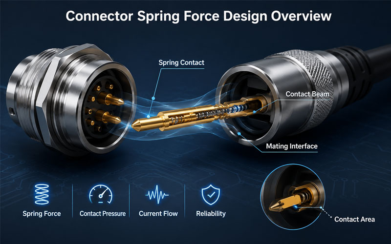
Connector Spring Force Design Overview

Inside every reliable connector is a carefully engineered contact system.

While connector housings provide mechanical protection, the spring force generated by the contact structure determines whether electrical connections remain stable during operation.

The correct spring force helps maintain:

  • Stable electrical contact
  • Low contact resistance
  • Resistance against vibration
  • Long mating cycle life

However, designing connector spring force is a balance.

Too little force may cause intermittent connections, while excessive force can increase insertion force and accelerate contact wear.

For automotive electronics, industrial automation, robotics, energy storage systems, and other demanding applications, spring force design is a key factor in connector reliability.

A reliable connector does not simply make contact.

It maintains consistent contact pressure throughout its service life.

Connector Spring Force Design Overview


What Is Spring Force in Connector Contacts?

Spring force refers to the mechanical force generated by the elastic deformation of a connector contact element after mating.

When two contacts are connected:

1.The male and female contacts engage.

2.The contact element deforms elastically.

3.The spring force pushes the surfaces together.

4.Stable electrical contact is maintained.

This force creates the necessary contact pressure for reliable current transmission.

Common spring structures include:

  • Cantilever beams
  • Dual-beam contacts
  • Leaf springs
  • Cage-style contacts
  • Elastic socket structures

Each design provides different performance characteristics.


Why Spring Force Matters in Connector Reliability

The contact interface is constantly exposed to mechanical and environmental stress.

A properly designed spring force helps maintain performance under:

  • Vibration
  • Shock
  • Thermal expansion
  • Repeated mating cycles
  • Mechanical movement

Without sufficient spring force, connectors may experience:

  • Increased contact resistance
  • Signal interruption
  • Electrical arcing
  • Local heating
  • Premature failure

1.Spring Force Maintains Stable Electrical Contact

Electrical current flows through the actual contact points between mating surfaces.

The spring force determines how tightly these surfaces remain connected.

Proper contact pressure helps:

✔ Increase effective contact area

✔ Reduce resistance variation

✔ Improve current stability

✔ Prevent micro-movement


Low Spring Force Problems

Insufficient spring force can cause:

Contact Interruption

Small movements caused by vibration may temporarily break the electrical connection.

Increased Resistance

Poor contact pressure creates unstable electrical pathways.

Fretting Corrosion

Micro-motion between metal surfaces may generate wear particles and oxidation.


Excessive Spring Force Problems

Too much force can create:

High Insertion Force

Users may experience difficulty during mating.

Faster Contact Wear

Higher mechanical stress accelerates surface damage.

Reduced Mating Life

Repeated cycles may permanently deform the contact structure.


2.Spring Force and Contact Resistance Relationship

Contact resistance is directly affected by contact pressure.

Higher contact pressure generally improves electrical performance by creating more stable metal-to-metal contact.

However, the relationship is not unlimited.

After reaching an optimal range, increasing force provides fewer benefits while increasing mechanical stress.

Connector engineers must optimize:

Contact Force + Material Elasticity + Surface Condition

to achieve long-term reliability.


3.Contact Spring Design Affects Connector Durability

Different contact structures generate spring force in different ways.


Cantilever Beam Contacts

A cantilever beam uses a flexible metal arm to create contact pressure.

Advantages:

✔ Simple structure

✔ Cost-effective manufacturing

✔ Good electrical performance

Common applications:

  • PCB connectors
  • Automotive connectors
  • General electronic connectors

Dual Beam Contacts

Dual beam designs use two independent contact points.

Advantages:

✔ Improved redundancy

✔ Better vibration resistance

✔ More stable connection

If one contact point experiences contamination or wear, the second contact can help maintain electrical continuity.


Leaf Spring Contacts

Leaf spring structures provide controlled elastic force.

Advantages:

✔ Stable pressure distribution

✔ Good mechanical durability

✔ Suitable for high-cycle applications


4.Spring Force Helps Improve Vibration Resistance

Many connectors operate in environments with continuous vibration.

Examples:

  • Vehicles
  • Robots
  • Industrial machinery
  • Outdoor equipment

Vibration can cause:

  • Contact separation
  • Fretting wear
  • Signal interruption

Proper spring force helps maintain contact pressure during mechanical movement.

This is especially important for:

  • Automotive connectors
  • Circular connectors
  • Industrial Ethernet connectors

5.Spring Force Influences Mating Cycle Life

Every connector mating cycle creates mechanical stress.

During repeated mating:

  • Contact surfaces slide
  • Spring elements deform
  • Plating layers experience wear

A well-designed spring system maintains:

✔ Stable force over time

✔ Controlled contact wear

✔ Reliable electrical performance

For connectors requiring thousands of mating cycles, spring force consistency is critical.


6.Material Selection Determines Spring Performance

Spring force depends heavily on contact material properties.

Important factors include:

  • Elastic strength
  • Fatigue resistance
  • Conductivity
  • Corrosion resistance

Common contact materials include:

Copper Alloys

Advantages:

✔ Good conductivity

✔ Balanced mechanical performance


Phosphor Bronze

Advantages:

✔ Excellent spring properties

✔ Good fatigue resistance

Commonly used for:

  • High-cycle connectors
  • Signal connectors

Beryllium Copper

Advantages:

✔ High elasticity

✔ Excellent mechanical durability

Used in applications requiring:

  • High reliability
  • Long service life

7.Spring Force Must Be Combined with Contact Plating

Spring force alone cannot guarantee reliability.

The contact surface also requires proper plating.


Gold Plating

Benefits:

✔ Low contact resistance

✔ Excellent corrosion resistance

✔ Long mating life

Suitable for:

  • Signal connectors
  • Precision applications

Tin Plating

Benefits:

✔ Cost-effective

✔ Suitable for many power applications

Suitable for:

  • General electrical connectors

8.Testing Spring Force and Contact Reliability

Connector manufacturers validate spring performance through testing.

Common tests include:


Insertion and Extraction Force Testing

Measures:

  • Required mating force
  • User operation performance
  • Mechanical consistency

Contact Resistance Testing

Evaluates:

  • Electrical stability
  • Contact performance

Mating Cycle Testing

Verifies:

  • Contact durability
  • Spring performance after repeated use

Vibration Testing

Evaluates:

  • Contact stability under mechanical stress

9.Spring Force Design Requirements by Application

Different industries require different spring force characteristics.

ApplicationSpring Force Requirements
Automotive ConnectorVibration resistance, stable contact pressure
Robotics ConnectorHigh cycle durability, mechanical stability
Industrial ConnectorReliable performance in harsh environments
Energy Storage ConnectorHigh current stability, thermal reliability
Medical ConnectorStable connection and low failure risk

Common Spring Force Design Mistakes

Design IssuePotential Failure
Insufficient spring forceIntermittent connection
Excessive spring forceHigh insertion force
Poor material selectionLoss of elasticity
Uneven pressure distributionContact instability
Incorrect plating combinationIncreased resistance

How FPIC Optimizes Connector Contact Reliability

FPIC focuses on connector reliability through:

✔ Precision contact structure design

✔ Optimized spring force control

✔ Material and plating selection

✔ Contact resistance testing

✔ Mechanical reliability validation

Connector designs are evaluated to ensure:

  • Stable electrical performance
  • Reliable mating cycles
  • Consistent production quality

Through engineering optimization and manufacturing control, FPIC supports customers with reliable connector solutions for industrial and automotive applications.


Final Thoughts

Spring force is one of the most important elements in connector contact reliability.

A successful connector design requires the right balance between:

  • Contact pressure
  • Electrical performance
  • Mechanical durability
  • User operation

Too little force creates unstable connections.

Too much force reduces usability and service life.

The best connector designs achieve controlled spring force that maintains reliable performance throughout thousands of operating cycles.

A connector is not reliable because the contacts touch.

It is reliable because the contacts remain stable.


FAQ

What is spring force in a connector?

Spring force is the mechanical force generated by the elastic deformation of connector contacts after mating.

Why is spring force important for connector reliability?

It maintains contact pressure, reduces resistance variation, and improves resistance to vibration and mechanical stress.

Can higher spring force improve connector performance?

Not always. Excessive force can increase wear and reduce mating cycle life.

How is connector spring force tested?

Manufacturers evaluate spring performance through insertion force, extraction force, contact resistance, mating cycle, and vibration tests.

What materials are commonly used for connector spring contacts?

Copper alloys, phosphor bronze, and beryllium copper are commonly used due to their electrical and elastic properties.


Need Reliable Connector Contact Design?

FPIC provides custom connector solutions with expertise in contact structure design, spring force optimization, material selection, and reliability testing.

From prototype development to mass production, FPIC helps OEM customers create connectors designed for long-term performance.

Contact FPIC today to discuss your connector project.


Resources

1.IEC 60512 – Connectors for Electronic Equipment – Tests and Measurements
https://www.iec.ch/

Connector testing methods covering mechanical and electrical performance evaluation.

2.EIA-364 Connector Test Standards
https://www.eia-global.org/

Industry standards for connector reliability and performance testing.

3.USCAR Connector Performance Standards
https://www.uscar.org/

Automotive connector performance requirements and validation guidelines.

Connector Reliability Overview

A connector is only as reliable as its contact system.

Although the external housing provides protection and mechanical support, the actual electrical connection happens at the contact interface.

The design of this small area determines whether a connector can maintain stable performance under:

  • High current loads
  • Vibration
  • Temperature changes
  • Repeated mating cycles
  • Harsh operating environments

For applications such as automotive electronics, industrial automation, robotics, energy storage systems, and medical equipment, contact geometry plays a critical role in connector reliability.

A well-designed connector does not simply make contact.

It maintains consistent electrical and mechanical performance throughout its service life.

Connector Reliability Overview


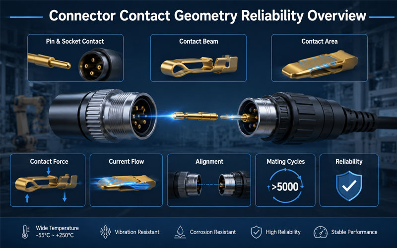
What Is Connector Contact Geometry?

Contact geometry refers to the physical design of the connector contact interface.

It includes:

  • Contact shape
  • Contact beam structure
  • Contact area
  • Contact engagement position
  • Contact pressure distribution
  • Wiping action during mating

The goal of contact geometry design is to achieve the right balance between:

  • Electrical conductivity
  • Mechanical strength
  • Contact stability
  • Mating durability

Different applications require different contact structures.

A high-current power connector and a high-speed signal connector may use completely different contact geometries because their performance requirements are different.


Why Contact Geometry Is Critical for Connector Reliability

When two connector contacts mate, several physical factors determine connection quality.

A reliable contact interface must provide:

Stable Electrical Path

Ensuring current can flow efficiently with minimal resistance.

Proper Contact Force

Maintaining connection stability without excessive mechanical stress.

Controlled Wear

Allowing repeated mating without rapid degradation.

Resistance to Environmental Stress

Maintaining performance against:

  • Vibration
  • Shock
  • Temperature variation
  • Corrosion

Poor contact geometry can result in:

  • Increased contact resistance
  • Intermittent electrical connection
  • Signal interruption
  • Excessive heat generation
  • Premature connector failure

1.Contact Shape Determines Connection Performance

The shape of the contact element directly affects current transmission and mechanical stability.

Common contact structures include:


Pin and Socket Contacts

Pin and socket designs are widely used in circular connectors and industrial connectors.

Advantages:

✔ Reliable alignment

✔ Stable contact interface

✔ Good environmental adaptability

The socket contact usually uses spring structures to maintain contact pressure around the pin.

This design helps compensate for:

  • Manufacturing tolerance
  • Vibration
  • Mechanical movement

Blade Contacts

Blade contacts provide a larger conductive path.

Advantages:

✔ High current capability

✔ Simple structure

✔ Good mechanical strength

They are commonly used in:

  • Power connectors
  • Automotive applications
  • Industrial equipment

Spring Contacts

Spring-based contacts use elastic deformation to maintain continuous pressure.

Advantages:

✔ Improved vibration resistance

✔ Stable contact force

✔ Longer service life

They are suitable for applications requiring frequent mating cycles.


2.Contact Force Affects Reliability and Mating Performance

Contact force is one of the most important design parameters.

The correct contact force ensures:

  • Stable electrical connection
  • Low contact resistance
  • Resistance to vibration

However, both insufficient and excessive force can create problems.


Too Low Contact Force

Potential issues:

  • Increased electrical resistance
  • Intermittent connection
  • Signal instability

Low contact force may allow micro-movement between contacts, causing electrical degradation over time.


Too High Contact Force

Potential issues:

  • Higher insertion force
  • Increased contact wear
  • Reduced mating cycles

A good connector design balances:

Contact Reliability + User Operation + Service Life


3.Contact Area Influences Current Flow and Heat Generation

The contact interface determines how efficiently electrical current transfers between mating components.

A well-designed contact area helps:

  • Reduce current concentration
  • Lower resistance
  • Minimize heat generation

However, contact area alone does not determine performance.

Engineers must also consider:

  • Contact pressure
  • Surface condition
  • Material properties
  • Contact alignment

A larger contact surface without proper pressure control may not provide better reliability.


4.Wiping Action Helps Maintain Clean Contact Surfaces

Many connector designs include wiping action during mating.

During insertion, the contact surfaces slide against each other.

This movement helps remove:

  • Dust particles
  • Surface oxidation
  • Minor contamination

Benefits include:

✔ Improved electrical stability

✔ Reduced contact resistance variation

✔ Better long-term reliability

Wiping action is especially important for:

  • Outdoor equipment
  • Industrial automation
  • High-cycle connectors

5.Contact Geometry Determines Mating Cycle Life

Every mating cycle creates mechanical stress on contacts.

Repeated connection and disconnection can cause:

  • Surface wear
  • Loss of contact force
  • Material deformation

A reliable contact design considers:

Contact Elasticity

Maintains pressure after repeated use.

Wear Resistance

Reduces surface damage.

Mechanical Stability

Prevents deformation during operation.

For connectors requiring thousands of mating cycles, optimized contact geometry is essential.


6.Alignment Design Prevents Contact Damage

Even a well-designed contact can fail if alignment is poor.

Incorrect alignment may cause:

  • Bent pins
  • Uneven contact pressure
  • Partial engagement
  • Contact damage

Reliable connector systems often include:

  • Polarization features
  • Guide structures
  • Mechanical keys
  • Alignment sleeves

These features ensure correct mating and protect the contact system.


7.Contact Geometry Influences Thermal Reliability

Electrical resistance generates heat.

When contact geometry is poor, current may concentrate in small areas, creating:

  • Hot spots
  • Temperature rise
  • Contact degradation

A properly designed contact structure improves:

  • Current distribution
  • Heat dissipation
  • Long-term stability

This is especially important for:

  • High-current connectors
  • Battery systems
  • Industrial power equipment

8.Contact Geometry Must Match Application Requirements

Different industries require different contact solutions.

ApplicationContact Design Priorities
AutomotiveVibration resistance, durability, stable contact force
RoboticsHigh mating cycles, mechanical stability
Industrial AutomationEnvironmental protection, reliability
Energy StorageHigh current capability, thermal control
Medical EquipmentStable signal transmission, safety

Connector design should always begin with understanding the actual application environment.


9.Contact Material and Plating Work Together with Geometry

Contact geometry is only one part of connector reliability.

Material selection and surface treatment are equally important.


Contact Material

Common materials include:

  • Copper alloys
  • Brass
  • Phosphor bronze

Important characteristics:

  • Electrical conductivity
  • Spring performance
  • Mechanical strength

Contact Plating

Gold Plating

Advantages:

✔ Excellent corrosion resistance

✔ Low contact resistance

✔ Long mating life

Suitable for:

  • Signal connectors
  • Precision applications

Tin Plating

Advantages:

✔ Cost-effective

✔ Suitable for many power applications

Suitable for:

  • General electrical connections

10.How FPIC Optimizes Connector Contact Design

FPIC focuses on connector reliability through:

Precision Contact Engineering

Including:

  • Contact structure optimization
  • Contact force control
  • Mechanical tolerance management

Material and Plating Selection

Considering:

  • Current requirements
  • Environment
  • Mating cycles

Reliability Testing

Including:

  • Contact resistance testing
  • Insertion and extraction force testing
  • Mating cycle evaluation
  • Environmental testing

Through engineering optimization and manufacturing control, FPIC helps customers develop reliable connector solutions for demanding applications.


Common Contact Geometry Design Mistakes

Design MistakePotential Result
Incorrect contact forceIntermittent connection
Poor alignment designContact damage
Insufficient contact areaHeat generation
Weak wiping actionIncreased resistance
Improper material selectionReduced service life

Contact Geometry Design Checklist

Before finalizing a connector design, engineers should evaluate:

✔ Is the contact force within the correct range?

✔ Can the contact maintain stability after repeated mating?

✔ Is current distribution optimized?

✔ Does the geometry support the application environment?

✔ Are material and plating choices appropriate?

✔ Has the design been validated through testing?


Final Thoughts

Contact geometry is one of the most important factors influencing connector reliability.

A reliable connector requires careful optimization of:

  • Contact shape
  • Contact force
  • Contact area
  • Alignment
  • Material selection
  • Surface treatment

The contact interface may be small, but it determines the overall performance of the connector system.

A connector is not reliable because it connects once.

It is reliable because it maintains a stable connection thousands of times under real-world conditions.


FAQ

What is contact geometry in connectors?

Contact geometry refers to the physical structure and design of the electrical contact interface, including shape, contact area, and pressure distribution.

How does contact geometry affect connector reliability?

It affects electrical resistance, current flow, mating durability, vibration resistance, and long-term performance.

Why is contact force important in connector design?

Proper contact force ensures stable electrical connection while balancing insertion force and wear.

Can contact geometry affect connector temperature?

Yes. Poor contact geometry can increase resistance and create localized heat generation.

How do engineers improve connector contact reliability?

Engineers optimize contact structure, materials, plating, alignment, and validate performance through reliability testing.


Need a Reliable Custom Connector Solution?

FPIC provides custom connector design and manufacturing services with expertise in contact engineering, material selection, reliability testing, and mass production.

From concept development to final production, FPIC helps OEM customers build connectors designed for long-term performance.

Contact FPIC today to discuss your connector requirements.


Resources

  1. IEC 60512 – Connectors for Electronic Equipment – Tests and Measurements
    https://www.iec.ch/
    Connector testing methods covering electrical and mechanical performance evaluation.
  2. EIA-364 Connector Test Standards
    https://www.eia-global.org/
    Industry test standards for connector reliability and performance validation.
  3. IPC/WHMA-A-620 – Requirements and Acceptance for Cable and Wire Harness Assemblies
    https://www.ipc.org/
    Industry acceptance criteria for cable and wire harness assemblies.
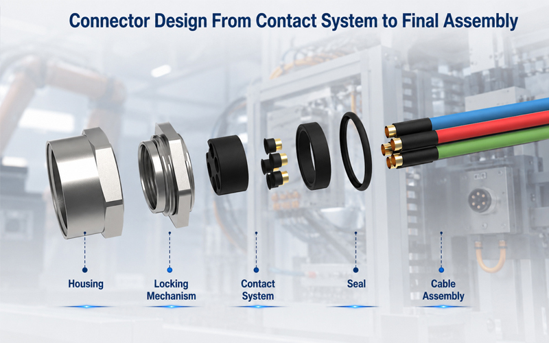
Connector Design From Contact System to Final Assembly

A connector may look like a simple component, but its performance depends on the interaction of multiple engineering elements.

A reliable connector requires careful design of:

  • Contact system
  • Housing structure
  • Locking mechanism
  • Sealing system
  • Material selection
  • Manufacturing process
  • Final assembly and testing

A mistake in any stage can affect:

  • Electrical performance
  • Mechanical reliability
  • Environmental protection
  • Service life

For engineers developing industrial, automotive, robotics, energy storage, and automation systems, connector design should be considered as a complete engineering process—not just a component selection task.

This guide explains the key stages of connector design, from the internal contact system to final production validation.

Connector Design From Contact System to Final Assembly


Why Connector Design Requires System-Level Thinking

A connector performs three primary functions:

Electrical Connection

Providing stable current or signal transmission.

Important factors:

Contact resistance

Current capacity

Signal integrity

Plating performance

Mechanical Connection

Maintaining a secure connection under real-world conditions.

Important factors:

Mating force

Locking structure

Vibration resistance

Mating cycles

Environmental Protection

Protecting internal components from harsh environments.

Important factors:

Waterproof sealing

Dust protection

Temperature resistance

Chemical exposure

A successful connector design balances all three requirements.


1.Contact System Design: The Core of Connector Performance

The contact system is the electrical heart of a connector.

Its design directly affects:

  • Conductivity
  • Heat generation
  • Reliability
  • Service life

Contact Geometry Design

Contact geometry determines how terminals connect and maintain contact force.

Key considerations include:

✔ Contact area

✔ Spring structure

✔ Contact pressure

✔ Current path design

A properly designed contact system provides:

Stable electrical connection

Low resistance

Long-term performance


Contact Material Selection

Common contact materials include:

Copper Alloys

Advantages:

✔ Good conductivity

✔ Balanced strength

✔ Cost efficiency

Phosphor Bronze

Advantages:

✔ Good spring performance

✔ Excellent fatigue resistance

Beryllium Copper

Advantages:

✔ High elasticity

✔ Excellent contact force retention

Used for:

  • High-cycle connectors
  • Precision applications

Contact Plating Selection

Surface plating affects:

  • Corrosion resistance
  • Contact stability
  • Mating life

Common options include:

Gold Plating

Advantages:

✔ Excellent corrosion resistance

✔ Reliable low contact resistance

Suitable for:

  • Signal connectors
  • Medical equipment
  • High-cycle applications

Tin Plating

Advantages:

✔ Cost-effective

✔ Suitable for many power applications

The correct plating depends on:

  • Current level
  • Environment
  • Required mating cycles

2.Housing Design: Mechanical Protection and Alignment

The connector housing protects internal contacts and ensures proper mating.

A good housing design must provide:

✔ Mechanical strength

✔ Accurate terminal positioning

✔ Electrical insulation

✔ Assembly efficiency


Housing Material Selection

Common materials include:

PA (Polyamide)

Used for:

  • Industrial connectors
  • General applications

Benefits:

  • Good strength
  • Cost efficiency

PBT

Benefits:

  • Dimensional stability
  • Low moisture absorption

PPS

Benefits:

  • High temperature resistance
  • Chemical resistance

Material selection depends on:

  • Operating temperature
  • Mechanical requirements
  • Environmental conditions

Terminal Positioning and Polarization

Connector housings should prevent incorrect assembly.

Important design features:

  • Keying structures
  • Polarization features
  • Secondary locks

These features help prevent:

❌ Wrong mating

❌ Terminal back-out

❌ Assembly mistakes


3.Locking Mechanism Design

A reliable locking system prevents accidental disconnection.

Common locking methods include:


Threaded Locking

Advantages:

✔ High vibration resistance

✔ Strong mechanical retention

Applications:

  • Industrial equipment
  • Outdoor systems

Push-Pull Locking

Advantages:

✔ Fast connection

✔ Easy operation

✔ High mating efficiency

Applications:

  • Medical
  • Automation
  • Test equipment

Snap Locking

Advantages:

✔ Simple operation

✔ Cost-effective

Applications:

  • General electronic applications

4.Sealing and Environmental Protection

For harsh environments, sealing design is critical.

Connector sealing protects against:

  • Water
  • Dust
  • Oil
  • Humidity

Common sealing components include:

  • O-rings
  • Gaskets
  • Rubber seals

IP Protection Considerations

Depending on the application, connectors may require:

  • IP67
  • IP68
  • IP69K

Higher protection levels require careful control of:

  • Seal compression
  • Housing interface
  • Material compatibility

5.Connector Assembly Design

Connector assembly affects both quality and manufacturing efficiency.

A production-ready design should consider:


Terminal Insertion

Important factors:

✔ Insertion force

✔ Terminal retention

✔ Position accuracy


Secondary Locking System

Secondary locks improve:

  • Terminal retention
  • Assembly reliability
  • Safety

Assembly Error Prevention

Good designs include:

  • Visual identification
  • Mechanical keying
  • Assembly guidance

These features improve production consistency.


6.Connector Validation and Testing

Before mass production, connectors require validation.

Common tests include:


Electrical Testing

Including:

  • Contact resistance
  • Insulation resistance
  • Hi-Pot testing

Mechanical Testing

Including:

  • Insertion force
  • Extraction force
  • Mating cycles
  • Vibration testing

Environmental Testing

Including:

  • Temperature cycling
  • Humidity testing
  • Salt spray testing
  • Water ingress testing

Testing ensures the connector performs under real application conditions.


7.Connector Design for Mass Production

A successful connector design must also consider manufacturing.

Key DFM considerations include:

Injection Molding

Evaluate:

  • Wall thickness
  • Draft angle
  • Mold complexity

Terminal Stamping

Evaluate:

  • Material utilization
  • Contact geometry
  • Production consistency

Assembly Automation

Evaluate:

  • Assembly direction
  • Process repeatability
  • Inspection requirements

Good connector design reduces production risks.


How FPIC Approaches Connector Design

FPIC provides customized connector solutions from engineering design through mass production.

Our connector development process considers:

  • Contact system design
  • Housing structure
  • Material selection
  • Manufacturing feasibility
  • Assembly optimization
  • Reliability testing

By combining engineering experience with manufacturing capability, FPIC helps customers develop connectors that meet demanding industrial requirements.


Final Thoughts

Connector design is a system engineering process.

A reliable connector requires the right balance between:

  • Contact performance
  • Mechanical structure
  • Environmental protection
  • Manufacturing efficiency

From the first contact design to final assembly validation, every detail influences long-term reliability.

For OEM engineers, selecting the right connector partner means choosing a team that understands both product performance and manufacturing reality.

A high-quality connector is not simply assembled—it is engineered.


FAQ

What are the main parts of a connector?

The main parts include contacts, housing, locking mechanism, sealing components, and assembly features.

Why is contact design important in connectors?

The contact system determines electrical performance, contact resistance, current capability, and mating reliability.

What factors affect connector lifetime?

Key factors include materials, contact force, mating cycles, environment, vibration, and manufacturing quality.

What tests are required for connector validation?

Common tests include electrical testing, mechanical testing, environmental testing, and durability testing.

Why should connector design consider manufacturing early?

Early manufacturing consideration improves production efficiency, reduces defects, and controls cost.


Need a Custom Connector Solution?

FPIC develops customized connector solutions for industrial automation, robotics, energy storage, automotive, and other demanding applications.

From contact design and material selection to tooling, assembly, and testing, FPIC supports customers from concept development to mass production.

Contact FPIC today to discuss your connector project.


Resources

  1. IEC 60512 – Connectors for Electronic Equipment – Tests and Measurements
    https://www.iec.ch/
    Connector testing methods covering electrical, mechanical, and environmental performance.
  2. IPC/WHMA-A-620 – Requirements and Acceptance for Cable and Wire Harness Assemblies
    https://www.ipc.org/
    Industry requirements for cable assembly quality and workmanship.
  3. ISO 16750 – Road Vehicles Environmental Conditions and Testing
    https://www.iso.org/
    Environmental testing guidance for automotive electrical components.
  4. IATF 16949 Automotive Quality Management System
    https://www.iatfglobaloversight.org/
    Automotive quality management requirements for production consistency.
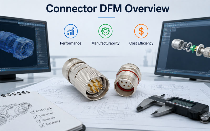
Connector DFM Design Optimization Overview

Designing a connector is not only about achieving the highest electrical performance.

A connector must also be:

  • Easy to manufacture
  • Consistent in mass production
  • Cost-effective
  • Reliable throughout its service life

Many connector designs fail to consider manufacturing requirements early enough.

The result can include:

  • Complex assembly processes
  • Higher tooling costs
  • Production delays
  • Difficult quality control
  • Increased unit cost

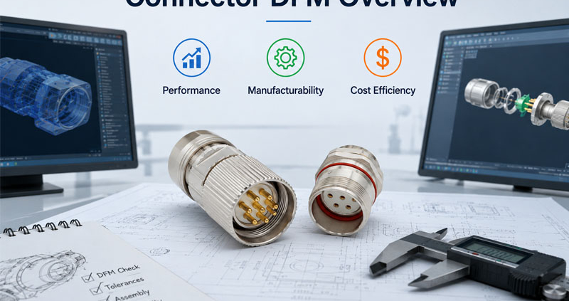
This is why Design for Manufacturing (DFM) plays an important role in connector development.

A successful connector design balances three key factors:

Performance + Manufacturability + Cost

Connector DFM Design Optimization Overview


What Is Connector DFM?

Connector DFM (Design for Manufacturing) is an engineering approach that considers production requirements during the design stage.

Instead of designing a connector first and solving manufacturing problems later, DFM integrates:

  • Material selection
  • Tooling requirements
  • Assembly processes
  • Testing methods
  • Production scalability

from the beginning.

The goal is to create a connector that performs well while remaining practical for high-volume manufacturing.


Why DFM Matters in Connector Development

A connector may perform well in a laboratory environment but face challenges during mass production.

Common issues caused by poor DFM include:

❌ Difficult assembly

❌ Tight manufacturing tolerances

❌ High tooling complexity

❌ Low production yield

❌ Increased inspection requirements

❌ Higher manufacturing cost

A DFM-focused design reduces these risks by considering the entire product lifecycle.


1.Design for Electrical Performance

The first priority of any connector is reliable electrical performance.

DFM does not mean reducing performance.

Instead, it means achieving required performance with an optimized design.

Key electrical considerations include:


Contact System Design

The contact structure affects:

  • Current capacity
  • Contact resistance
  • Mating cycles
  • Signal integrity

Engineers should evaluate:

✔ Contact geometry

✔ Contact force

✔ Material selection

✔ Plating thickness

✔ Current path design

A well-designed contact system improves reliability while avoiding unnecessary material costs.


Creepage and Clearance Design

For higher voltage applications, spacing requirements are critical.

Proper DFM considers:

  • Insulation distance
  • Housing structure
  • Manufacturing capability

Over-designing spacing may increase connector size and cost.

Under-designing may create safety risks.

The goal is the correct balance.


2.Design for Manufacturability

A connector designed for manufacturing should support stable and efficient production.

Important factors include:

Simplify Connector Structure

Complex structures increase:

  • Mold difficulty
  • Assembly steps
  • Failure risks

Good DFM practices include:

✔ Reducing unnecessary components

✔ Simplifying assembly direction

✔ Minimizing manual operations

✔ Improving part consistency


Optimize Housing Design

The connector housing must consider injection molding requirements.

Important factors:

  • Wall thickness
  • Draft angles
  • Rib design
  • Shrinkage control
  • Mold release

Poor housing design can lead to:

  • Warpage
  • Cracks
  • Dimensional variation

Improve Assembly Efficiency

Mass production requires repeatable assembly.

Design considerations:

✔ Easy terminal insertion

✔ Clear orientation features

✔ Locking mechanism feedback

✔ Error-proof assembly

These features reduce production errors and improve efficiency.


3.Material Selection for DFM

Material selection affects both performance and manufacturing cost.

Important factors include:

  • Temperature resistance
  • Mechanical strength
  • Chemical resistance
  • Processing requirements

Common connector materials:


Housing Materials

PA (Polyamide)

Advantages:

✔ Good mechanical strength

✔ Cost-effective

✔ Widely available

PBT

Advantages:

✔ Dimensional stability

✔ Good electrical insulation

PPS

Advantages:

✔ High temperature performance

✔ Excellent chemical resistance

The right material depends on the application requirements.


Contact Materials

Common choices:

  • Copper alloys
  • Phosphor bronze
  • Beryllium copper

Selection depends on:

  • Conductivity
  • Spring performance
  • Mating cycles
  • Cost targets

4.Design for Tooling Efficiency

Connector tooling can represent a significant development investment.

DFM helps reduce tooling complexity.

Key considerations:

Mold Design

Good connector designs consider:

✔ Fewer sliders

✔ Simple parting lines

✔ Stable cavity design

✔ Easy maintenance


Terminal Stamping Design

Terminal design affects:

  • Material usage
  • Stamping speed
  • Production consistency

Optimized terminal geometry can reduce:

  • Material waste
  • Processing cost
  • Defect rates

5.Balancing Performance and Cost

The lowest-cost connector is not always the most economical solution.

A cheaper connector may create:

  • Higher failure risk
  • More maintenance
  • Increased warranty costs

Effective cost optimization focuses on:

Right Specification

Avoid unnecessary features.

Example:

Not every application requires:

  • Premium plating
  • Extreme temperature materials
  • Maximum mating cycles

Production Efficiency

Reduce cost through:

✔ Better tooling design

✔ Automated assembly

✔ Higher yield

✔ Reduced inspection time


Lifecycle Cost

A reliable connector can reduce:

  • Downtime
  • Replacement costs
  • Field failures

The best design optimizes total value, not only unit price.


6.DFM Review Process for Connector Development

A typical connector DFM review includes:

Step 1: Requirement Analysis

Evaluate:

  • Electrical requirements
  • Mechanical conditions
  • Environmental exposure
  • Cost targets

Step 2: Design Review

Check:

  • Structure
  • Materials
  • Tolerances
  • Assembly method

Step 3: Manufacturing Evaluation

Review:

  • Mold feasibility
  • Stamping process
  • Automation possibility
  • Testing requirements

Step 4: Prototype Validation

Perform:

  • Dimensional inspection
  • Electrical testing
  • Mechanical testing
  • Environmental testing

Step 5: Mass Production Optimization

Monitor:

  • Yield
  • Process stability
  • Quality data
  • Cost performance

How FPIC Applies DFM Principles to Connector Development

FPIC supports customers from connector concept development to mass production.

Our engineering approach considers:

  • Application requirements
  • Connector structure
  • Material selection
  • Tooling feasibility
  • Assembly efficiency
  • Quality validation

Through DFM-driven development, FPIC helps customers achieve connectors that are:

✔ Reliable

✔ Manufacturable

✔ Cost-efficient

✔ Ready for mass production


Final Thoughts

A successful connector design requires more than excellent technical specifications.

The best connector balances:

  • Electrical performance
  • Mechanical reliability
  • Manufacturing efficiency
  • Cost control

By applying DFM principles early, engineers can reduce development risks, improve production consistency, and create products that perform reliably in real-world applications.

Good connector design begins before production starts.


FAQ

What does DFM mean in connector design?

DFM means Design for Manufacturing, an approach that optimizes connector design for efficient and reliable production.

Why is DFM important for connectors?

DFM reduces manufacturing problems, improves production yield, lowers cost, and helps ensure consistent quality.

Does DFM reduce connector performance?

No. Proper DFM achieves the required performance while improving manufacturability and cost efficiency.

What factors should be considered during connector DFM?

Engineers should consider materials, tooling, assembly process, tolerances, testing, and production requirements.

When should DFM review happen?

DFM should begin during the early connector design stage before tooling and mass production.


Need a Connector Designed for Mass Production?

FPIC provides customized connector solutions with engineering support from design optimization to volume manufacturing.

With experience in connector development, tooling coordination, assembly, and testing, FPIC helps OEM customers create reliable and production-ready connector solutions.

Contact FPIC today to discuss your connector development project.


Resources

  1. IEC 60512 – Connectors for Electronic Equipment – Tests and Measurements
    https://www.iec.ch/
    Connector testing methods for electrical and mechanical performance evaluation.
  2. IPC/WHMA-A-620 – Requirements and Acceptance for Cable and Wire Harness Assemblies
    https://www.ipc.org/
    Industry requirements for cable and harness manufacturing quality.
  3. ISO 9001 Quality Management Systems
    https://www.iso.org/iso-9001-quality-management.html
    Quality management principles supporting consistent manufacturing processes.
  4. IATF 16949 Automotive Quality Management System
    https://www.iatfglobaloversight.org/
    Automotive quality requirements focused on process control and defect prevention.
Connector Material Selection Overview

Selecting the right connector is not only about choosing the correct pin count, current rating, or mating interface.

The materials used inside a connector directly influence its reliability, durability, and performance throughout the product lifecycle.

A connector operating in a factory automation system, outdoor equipment, medical device, or energy storage application may face completely different challenges, including:

  • High temperature
  • Vibration
  • Moisture exposure
  • Chemical contamination
  • Mechanical stress
  • Frequent mating cycles

To achieve stable performance, engineers must carefully evaluate three major material categories:

  • Housing resin
  • Seal materials
  • Contact alloys and plating

Each material plays a different role in protecting electrical performance and mechanical reliability.

Connector Material Selection Overview


Why Connector Material Selection Matters

A connector is a combination of mechanical, electrical, and environmental protection components.

Poor material selection can lead to:

  • Cracked connector housings
  • Seal degradation
  • Increased contact resistance
  • Corrosion
  • Signal instability
  • Reduced mating life

For high-reliability applications, connector materials must match the actual operating environment rather than only meeting basic specifications.

A connector designed for indoor electronics may not perform reliably in outdoor or industrial conditions.


1.Connector Housing Resin Selection

The connector housing provides mechanical support and protects internal contacts.

Important properties include:

  • Mechanical strength
  • Temperature resistance
  • Chemical resistance
  • Dimensional stability
  • Flame retardancy
  • Insulation performance

Common housing materials include:


PA (Polyamide / Nylon)

PA is widely used for industrial and automotive connectors.

Advantages:

✔ Good mechanical strength

✔ Good wear resistance

✔ Cost-effective

✔ Suitable for many general applications

Limitations:

  • Absorbs moisture
  • Dimensional changes may occur in humid environments

Typical applications:

  • Automotive connectors
  • Industrial equipment
  • Wire harness systems

PBT (Polybutylene Terephthalate)

PBT is commonly used where dimensional stability and electrical insulation are important.

Advantages:

✔ Low moisture absorption

✔ Good chemical resistance

✔ Stable dimensions

✔ Good electrical performance

Typical applications:

  • Automotive electronics
  • Industrial connectors
  • Control systems

PPS (Polyphenylene Sulfide)

PPS is selected for demanding environments.

Advantages:

✔ Excellent temperature resistance

✔ High dimensional stability

✔ Strong chemical resistance

✔ Low moisture absorption

Typical applications:

  • High-temperature equipment
  • Industrial machinery
  • Automotive engine environments

PC (Polycarbonate)

PC provides high impact resistance.

Advantages:

✔ Excellent toughness

✔ Transparent options available

✔ Good impact strength

Typical applications:

  • Protective housings
  • Specialized electronic connectors

2.Connector Seal Material Selection

For outdoor and harsh environments, sealing materials are critical.

Seals protect connectors from:

  • Water
  • Dust
  • Oil
  • Chemicals
  • Humidity

Common sealing materials include:


Silicone Rubber

Advantages:

✔ Wide temperature range

✔ Excellent flexibility

✔ Long-term elasticity

✔ Good weather resistance

Applications:

  • Outdoor connectors
  • Medical equipment
  • High-temperature environments

EPDM Rubber

Advantages:

✔ Excellent water resistance

✔ Good ozone resistance

✔ Good weather durability

Applications:

  • Automotive
  • Outdoor industrial equipment

Fluorosilicone

Advantages:

✔ Chemical resistance

✔ Fuel and oil resistance

✔ Wide temperature capability

Applications:

  • Aerospace
  • Automotive
  • Harsh chemical environments

3.Contact Alloy Selection

The contact system determines electrical performance.

A contact must provide:

  • Stable conductivity
  • Low contact resistance
  • Mechanical durability
  • Corrosion resistance

Common contact materials include:


Copper Alloys

Copper alloys are widely used because they provide:

✔ Good electrical conductivity

✔ Good mechanical strength

✔ Reliable spring characteristics

Common materials:

  • Brass
  • Phosphor bronze
  • Copper alloy

Phosphor Bronze

Advantages:

✔ Excellent spring performance

✔ Good fatigue resistance

✔ Stable contact force

Applications:

  • High mating cycle connectors
  • Industrial connectors

Beryllium Copper

Beryllium copper is used for high-performance contact systems.

Advantages:

✔ Excellent elasticity

✔ High contact force retention

✔ Excellent fatigue resistance

Applications:

  • Precision connectors
  • High-cycle applications

4.Contact Plating Selection

The base alloy is only part of the contact performance.

Surface plating affects:

  • Contact resistance
  • Corrosion resistance
  • Mating cycle life

Common plating options:


Gold Plating

Advantages:

✔ Excellent corrosion resistance

✔ Stable electrical performance

✔ Suitable for high mating cycles

Applications:

  • Medical equipment
  • Communication systems
  • Precision electronics

Tin Plating

Advantages:

✔ Cost-effective

✔ Good solderability

✔ Suitable for many power applications

Limitations:

  • Lower corrosion resistance compared with gold

Applications:

  • General industrial connections
  • Power terminals

5.Matching Materials to Application Environments

Different applications require different material combinations.

Different applications require different material combinations.

ApplicationHousingSealContact
Industrial AutomationPA/PBTSilicone/EPDMCopper Alloy + Plating
Outdoor EquipmentPBT/PPSEPDM/SiliconeCorrosion-resistant contacts
Medical EquipmentEngineering PlasticSiliconeGold-plated contacts
RoboticsPBT/PAFlexible SealsHigh-cycle contact alloys
Energy StorageHigh-strength ResinHigh-temperature SealHigh-current Copper Alloy

Material selection should always consider:

  • Temperature range
  • Current load
  • Mechanical movement
  • Environmental exposure
  • Required service life

6.Material Selection and Connector Reliability Testing

Material selection should be supported by validation testing.

Common tests include:

Environmental Testing

  • Temperature cycling
  • Humidity testing
  • Salt spray testing

Mechanical Testing

  • Insertion and extraction force
  • Mating cycle testing
  • Vibration testing

Electrical Testing

  • Contact resistance testing
  • Insulation resistance
  • High-voltage testing

Testing confirms that the selected materials can perform reliably under real operating conditions.


How FPIC Approaches Connector Material Selection

FPIC develops and manufactures connector solutions for industrial automation, energy storage, automotive, robotics, and other demanding applications.

Our connector designs consider:

  • Housing material performance
  • Contact reliability
  • Environmental requirements
  • Mechanical durability
  • Application-specific testing

By combining material selection with engineering validation, FPIC helps customers achieve reliable connector performance from prototype development through mass production.


Final Thoughts

Connector reliability begins with material selection.

The housing resin protects the structure, sealing materials prevent environmental damage, and contact alloys ensure stable electrical performance.

Choosing the right combination requires understanding the application’s:

  • Temperature
  • Environment
  • Electrical requirements
  • Mechanical stress
  • Service life expectations

For engineers and OEM buyers, evaluating connector materials early in the design process can significantly reduce field failures and improve long-term system reliability.

The best connector is not only designed correctly—it is built with the right materials.


FAQ

What is the most important material in a connector?

There is no single most important material. Housing resin, seals, and contact materials work together to determine connector performance.

Why does connector housing material matter?

The housing provides mechanical protection, insulation, and environmental resistance for internal contacts.

What is the difference between gold and tin contacts?

Gold provides better corrosion resistance and longer mating life, while tin is more cost-effective for many general applications.

Which seal material is best for outdoor connectors?

Silicone and EPDM are commonly used because of their weather resistance and durability.

How do engineers select connector materials?

Engineers evaluate temperature, environment, electrical load, mating cycles, mechanical stress, and reliability requirements.


Need a Connector Designed for Your Application?

FPIC provides customized connector solutions for industrial automation, robotics, energy storage, automotive, and other demanding applications.

From material selection and connector design to testing and mass production, FPIC helps customers build reliable interconnection systems.

Contact FPIC today to discuss your connector requirements.


Resources

  1. IEC 60529 – Degrees of Protection Provided by Enclosures (IP Code)
    https://www.iec.ch/
    International standard defining protection levels against dust and water ingress.
  2. IPC/WHMA-A-620 – Requirements and Acceptance for Cable and Wire Harness Assemblies
    https://www.ipc.org/
    Industry standard covering cable assembly workmanship and acceptance criteria.
  3. IEC 60512 – Connectors for Electronic Equipment – Tests and Measurements
    https://www.iec.ch/
    Provides test methods for connector electrical and mechanical performance.
  4. UL Solutions – Connector and Electrical Component Safety
    https://www.ul.com/
    Technical resources related to electrical component safety and reliability.
  5. ISO 16750 – Road Vehicles Environmental Conditions and Testing
    https://www.iso.org/
    Environmental testing guidance for automotive electrical and electronic components.
Overmolded Connector Cable Assembly Overview

Connector cable assemblies are widely used in industrial automation, robotics, medical equipment, transportation, energy systems, and outdoor applications where reliability is critical.

While connector selection and cable specifications are important, the connection between the cable and connector is often the weakest point in a system. Repeated bending, vibration, moisture exposure, and mechanical stress can gradually damage this area and lead to electrical failures.

Overmolding technology provides an effective solution by creating a strong, integrated protective structure around the connector and cable transition area.

By improving sealing, strain relief, and mechanical protection, overmolding helps extend service life and improve the reliability of cable assemblies in demanding environments.

Overmolded Connector Cable Assembly Overview


What Is Overmolding in Connector Cable Assemblies?

Overmolding is a manufacturing process where a protective material is molded directly around a connector, cable exit, or existing assembly component.

During the process:

1.The connector and cable are positioned inside a mold.

2.A thermoplastic or elastomer material is injected around the assembly.

3.The material forms a permanent protective layer.

4.The finished assembly becomes a single integrated component.

Unlike traditional methods that rely only on external boots or mechanical clamps, overmolding creates a seamless connection between the connector and cable.


Why Connector Cable Assemblies Need Overmolding

The cable exit area experiences some of the highest mechanical stress in an assembly.

Common failure causes include:

  • Repeated bending
  • Pulling force
  • Vibration
  • Moisture penetration
  • Cable twisting
  • Connector loosening

Without proper protection, these stresses can cause:

  • Broken conductors
  • Damaged insulation
  • Seal failure
  • Intermittent electrical connections
  • Reduced service life

Overmolding strengthens this critical transition area and improves overall assembly durability.


1.Improved Strain Relief and Mechanical Protection

One of the biggest advantages of overmolding is enhanced strain relief.

During operation, cables may experience:

  • Pulling force
  • Bending cycles
  • Repeated movement
  • Installation stress

A properly designed overmold distributes mechanical stress over a larger area instead of concentrating it at the cable exit.

Benefits include:

✔ Reduced cable fatigue

✔ Improved bend resistance

✔ Better pull-force performance

✔ Longer cable life

For applications such as robotics, servo systems, and moving machinery, effective strain relief is essential.


2.Enhanced Waterproof and Environmental Protection

Many industrial applications require protection against moisture, dust, chemicals, and harsh environments.

Overmolding creates a sealed structure that reduces the risk of:

  • Water ingress
  • Dust contamination
  • Corrosion
  • Chemical exposure

Depending on design and material selection, overmolded cable assemblies can support demanding protection requirements such as IP-rated applications.

Typical applications include:

  • Outdoor equipment
  • Industrial sensors
  • Automation systems
  • Medical devices
  • Transportation equipment

3.Increased Vibration and Shock Resistance

Industrial environments often expose connectors to continuous vibration and mechanical impact.

Examples include:

  • Robotics
  • CNC equipment
  • Construction machinery
  • Vehicle systems

Overmolding helps secure the connector-to-cable interface by:

  • Reducing connector movement
  • Supporting cable orientation
  • Absorbing mechanical stress
  • Preventing loosening

This improves reliability in applications where equipment operates continuously.


4.Better Protection Against Contamination

Traditional connector assemblies may have gaps where dust, oil, or moisture can accumulate.

Overmolding creates a smooth external surface that helps prevent contamination buildup.

Advantages include:

  • Easier cleaning
  • Improved hygiene
  • Reduced corrosion risk
  • Better long-term stability

This is especially valuable in:

  • Medical equipment
  • Food processing systems
  • Laboratory instruments

5.Improved Cable Assembly Durability During Installation

Cable assemblies are often exposed to handling stress before installation.

Overmolding protects critical areas during:

  • Transportation
  • Installation
  • Maintenance
  • Equipment replacement

A robust molded structure reduces accidental damage and improves field reliability.


Material Selection Matters in Overmolding

The performance of an overmolded cable assembly depends heavily on material selection.

Common materials include:

PVC

Advantages:

  • Cost-effective
  • Good flexibility
  • Suitable for general industrial applications

TPU

Advantages:

  • Excellent abrasion resistance
  • High flexibility
  • Good mechanical strength

Common applications:

  • Robotics
  • Motion systems
  • Industrial automation

Silicone

Advantages:

  • Wide temperature range
  • Excellent flexibility
  • Medical compatibility

Common applications:

  • Medical equipment
  • High-temperature environments

Choosing the correct material depends on:

  • Temperature requirements
  • Chemical exposure
  • Flexing cycles
  • Environmental conditions

Overmolding Design Considerations

A successful overmolded cable assembly requires careful engineering.

Important considerations include:

Cable Exit Design

The transition area must provide:

  • Smooth stress distribution
  • Proper bending support
  • Adequate sealing

Material Compatibility

The overmold material must bond properly with:

  • Cable jacket
  • Connector housing
  • Sealing components

Application Requirements

Engineers should evaluate:

  • Static or dynamic movement
  • Operating temperature
  • IP protection requirements
  • Mechanical loads
  • Expected service life

How FPIC Provides Overmolded Connector Cable Assembly Solutions

FPIC provides customized connector cable assemblies with overmolding capabilities for industrial, medical, automation, and harsh-environment applications.

Our manufacturing capabilities include:

  • Custom connector integration
  • Cable assembly production
  • Overmolding solutions
  • Electrical testing
  • High-volume manufacturing

By combining engineering design with controlled manufacturing processes, FPIC helps customers achieve reliable cable assemblies with improved mechanical protection and long-term performance.


Final Thoughts

Overmolding is more than an appearance improvement—it is a reliability enhancement technology.

By strengthening the connector-to-cable transition area, improving sealing, and reducing mechanical stress, overmolding helps cable assemblies perform reliably in challenging environments.

For OEM customers, selecting the right overmolded connector cable assembly can reduce maintenance costs, minimize failures, and extend equipment service life.

A reliable connection starts with protecting the weakest point.


FAQ

What is overmolding in cable assemblies?

Overmolding is a process where protective material is molded around a connector and cable interface to create an integrated, durable assembly.

Why is overmolding important for connector cables?

It improves strain relief, sealing, vibration resistance, and mechanical protection, helping extend cable assembly life.

Are overmolded cable assemblies waterproof?

Properly designed overmolded assemblies can provide enhanced environmental protection and support IP-rated applications.

Which materials are commonly used for cable overmolding?

Common materials include PVC, TPU, and silicone, depending on flexibility, temperature, and environmental requirements.

What applications use overmolded cable assemblies?

They are widely used in robotics, industrial automation, medical equipment, outdoor systems, transportation, and energy applications.


Need Custom Overmolded Connector Cable Assemblies?

FPIC specializes in customized connector cable assemblies with overmolding solutions for demanding industrial applications.

From connector selection and cable design to molding, testing, and mass production, FPIC provides reliable interconnection solutions designed for long-term performance.

Contact FPIC today to discuss your custom cable assembly requirements.


Resources

  1. IPC/WHMA-A-620 – Requirements and Acceptance for Cable and Wire Harness Assemblies
    https://www.ipc.org/
    Industry standard covering workmanship, inspection, and acceptance requirements for cable and wire harness assemblies.
  2. IEC 60529 – Degrees of Protection Provided by Enclosures (IP Code)
    https://www.iec.ch/
    Defines protection levels against dust and water ingress for electrical equipment.
  3. UL Solutions – Cable and Wire Safety Resources
    https://www.ul.com/
    Provides technical information related to cable safety, materials, and performance requirements.
  4. ISO 10993 – Biological Evaluation of Medical Devices
    https://www.iso.org/standard/68936.html
    Provides evaluation guidance for materials used in medical applications.
  5. WHMA – Wire Harness Manufacturer’s Association
    https://www.whma.org/
    Provides industry resources and best practices for cable assembly and harness manufacturing.
Connector Insertion Force and Extraction Force Overview

When selecting an electrical connector, engineers often focus on current rating, IP protection, contact configuration, or signal performance. However, one mechanical characteristic is frequently underestimated—mating force.

Insertion force and extraction force directly influence how a connector performs during installation, maintenance, and long-term operation. If the insertion force is too high, installation becomes difficult and contact damage may occur. If the extraction force is too low, vibration or accidental pulling can cause unexpected disconnection.

Achieving the right balance between these two forces is essential for maintaining connector reliability throughout the product lifecycle.

Connector Insertion Force and Extraction Force Overview


What Are Insertion Force and Extraction Force?

Insertion force is the amount of force required to fully mate two connectors.

Extraction force is the force needed to separate them after they are connected.

Both values are carefully engineered and verified during connector development because they affect:

  • Installation efficiency
  • Contact stability
  • User experience
  • Mechanical reliability
  • Long-term electrical performance

Reliable connectors are designed to maintain consistent insertion and extraction forces throughout thousands of mating cycles.


Why Insertion Force Matters

A connector requiring excessive insertion force may create several practical issues

Typical problems include:

  • Difficult installation
  • Increased operator fatigue
  • Connector misalignment
  • Bent contacts
  • Housing damage

These risks become even more significant in compact equipment where installation space is limited.

Applications such as medical devices, portable instruments, and electronic test systems benefit from connectors that provide smooth and controlled insertion without sacrificing contact reliability.


Why Extraction Force Is Equally Important

Extraction force determines how securely a connector remains engaged during operation.

If extraction force is too low, connectors may disconnect due to:

  • Equipment vibration
  • Cable movement
  • Mechanical shock
  • Operator handling
  • Repeated motion

Conversely, excessive extraction force may increase maintenance time and make field servicing unnecessarily difficult.

The goal is to achieve secure retention while allowing efficient maintenance.


Contact Force Determines Electrical Stability

Insertion and extraction forces are closely related to contact force.

Proper contact force ensures:

  • Stable electrical continuity
  • Low contact resistance
  • Consistent signal transmission
  • Reduced micro-motion
  • Lower risk of fretting corrosion

If contact force decreases over time, electrical resistance may increase, leading to intermittent signals or localized heating.

For high-speed data transmission and low-current signal applications, stable contact force is particularly important.


Mating Force Changes Over Connector Life

Insertion and extraction forces are not fixed values.

Over thousands of mating cycles, they may gradually change due to:

  • Contact wear
  • Spring fatigue
  • Surface contamination
  • Plating wear
  • Mechanical deformation

Connector manufacturers therefore perform mating cycle tests to verify that insertion force, extraction force, and electrical performance remain within specification throughout the product’s expected service life.


Different Applications Require Different Force Levels

There is no universal mating force suitable for every connector.

Medical Equipment

Priority:

  • Smooth insertion
  • Frequent mating
  • Operator comfort
  • Reliable electrical contact

Industrial Automation

Priority:

  • Secure retention
  • Vibration resistance
  • Stable contact pressure
  • Long service life

Outdoor Equipment

Priority:

  • Reliable locking
  • Environmental sealing
  • Resistance to cable pull
  • Stable performance under harsh conditions

Connector selection should always reflect the actual mechanical demands of the application.


Locking Mechanisms Influence Mating Force

Different locking systems distribute insertion and extraction forces differently.

Push-Pull Connectors

Advantages:

  • One-handed operation
  • Fast mating
  • Automatic locking
  • Consistent extraction force

Ideal for:

  • Medical equipment
  • Robotics
  • Test equipment

Threaded Connectors

Advantages:

  • Strong mechanical retention
  • Excellent vibration resistance
  • High pull-out resistance

Ideal for:

  • Servo systems
  • Machine tools
  • Heavy industrial equipment

The locking mechanism should be selected together with the required mating force to achieve optimal reliability.


How Connector Manufacturers Validate Mating Force

Reliable connector manufacturers evaluate mating force using standardized mechanical testing.

Typical validation includes:

  • Insertion force measurement
  • Extraction force measurement
  • Mating cycle durability testing
  • Contact resistance testing
  • Vibration testing
  • Mechanical shock testing
  • Environmental exposure testing

These tests ensure the connector maintains both mechanical integrity and electrical performance throughout its service life.


How FPIC Designs Reliable Connector Interfaces

FPIC develops circular connectors, push-pull self-locking connectors, waterproof connectors, and customized cable assemblies for industrial automation, robotics, medical devices, and outdoor equipment.

Our connectors are engineered with optimized contact structures, precision locking mechanisms, and durable contact materials to provide balanced insertion and extraction forces. Combined with rigorous durability and electrical testing, these designs help maintain stable connections and long-term reliability even in demanding operating environments.


Final Thoughts

Insertion force and extraction force are far more than mechanical specifications.

They influence installation efficiency, maintenance convenience, contact stability, vibration resistance, and overall connector reliability.

Selecting a connector with properly balanced mating forces helps reduce installation errors, prevent accidental disconnection, and maintain consistent electrical performance throughout the equipment lifecycle.


FAQ

What is connector insertion force?

Insertion force is the mechanical force required to fully engage two mating connectors.

Why is extraction force important?

Extraction force determines how securely a connector remains connected during vibration, movement, and everyday operation while still allowing efficient maintenance.

Can insertion force change over time?

Yes. Contact wear, spring fatigue, plating wear, and contamination may gradually change insertion and extraction forces after repeated mating cycles.

Does higher insertion force mean a more reliable connector?

Not always. Excessive insertion force can increase wear and installation difficulty. Reliable connectors achieve a balance between secure contact and ease of use.

How are insertion and extraction forces tested?

Manufacturers measure these forces using standardized mechanical testing before and after durability, vibration, and environmental testing to verify long-term performance.


Looking for Reliable Circular Connector Solutions?

FPIC provides circular connectors, push-pull self-locking connectors, waterproof connectors, and custom cable assemblies engineered for reliable mating performance. From optimized insertion force to secure locking and long-term durability, our connector solutions help improve equipment reliability across industrial automation, robotics, medical devices, and outdoor applications.

Contact FPIC today to discuss the right connector solution for your project.


Resources

  1. IEC 60512 – Connectors for Electronic Equipment – Tests and Measurements
    https://webstore.iec.ch/
    Defines standardized mechanical and electrical test methods, including insertion force, withdrawal force, durability, and contact resistance.
  2. IEC 61076 – Connectors for Electrical and Electronic Equipment
    https://webstore.iec.ch/
    Provides international standards for the design, performance, and testing of circular and industrial connectors.
  3. USCAR-2 – Performance Specification for Automotive Electrical Connector Systems
    https://www.uscar.org/
    Describes mechanical performance requirements, including connector mating and unmating force evaluation for high-reliability applications.
  4. TE Connectivity – Connector Mechanical Performance
    https://www.te.com/
    Engineering resources explaining connector mating force, contact retention, and long-term mechanical reliability.
  5. Molex – Connector Design Considerations
    https://www.molex.com/
    Provides technical guidance on connector mating performance, contact systems, and durability testing.
Connector Hot Spots Failure Analysis

Connector hot spots are one of the most common causes of electrical failures in industrial equipment. Excessive heat at the contact interface can lead to increased resistance, insulation damage, intermittent connections, and even complete system shutdown.

While many engineers initially suspect excessive current, overheating is often the result of multiple interacting factors, including poor contact quality, improper assembly, environmental conditions, and long-term mechanical wear.

Understanding why hot spots develop is essential for designing reliable electrical systems and reducing unplanned maintenance.

Connector Hot Spots Failure Analysis


What Is a Connector Hot Spot?

A hot spot is a localized area where the connector temperature becomes significantly higher than surrounding components.

Unlike normal operating temperature rise, a hot spot indicates that electrical energy is being converted into heat due to excessive resistance at a specific location.

Typical hot spot locations include:

  • Contact interfaces
  • Crimp terminals
  • Wire-to-terminal transitions
  • Damaged contact surfaces
  • Loose mechanical connections

Because the heating is localized, the problem may remain unnoticed until the connector begins to discolor, deform, or fail.


High Contact Resistance Is the Most Common Cause

Electrical power loss follows the equation:

Power = I²R

Even a small increase in contact resistance can generate substantial heat when carrying moderate or high current.

Contact resistance may increase due to:

  • Poor contact force
  • Surface oxidation
  • Contamination
  • Contact wear
  • Incorrect plating selection

As resistance increases, higher temperatures further accelerate oxidation, creating a self-reinforcing cycle that eventually results in connector failure.


Loose Connections Generate Excessive Heat

Mechanical stability directly influences electrical performance.

Loose terminals reduce effective contact area, increasing resistance and creating localized heating.

Common causes include:

  • Improper torque
  • Incomplete terminal insertion
  • Connector vibration
  • Repeated mechanical movement
  • Poor locking mechanisms

Secure locking systems help maintain consistent contact pressure throughout the connector’s service life.


Poor Crimp Quality Can Create Hidden Hot Spots

Many overheating problems originate in the crimp rather than at the mating contacts.

Typical crimp defects include:

  • Under-crimping
  • Over-crimping
  • Damaged conductor strands
  • Incorrect wire size
  • Incomplete conductor insertion

A properly designed crimp should create a gas-tight connection with minimal electrical resistance.

Routine pull-force testing and crimp cross-section analysis help verify crimp quality before production.


Contact Plating Influences Long-Term Performance

Connector plating affects corrosion resistance, wear resistance, and long-term contact stability.

For example:

Gold-Plated Contacts

  • Excellent corrosion resistance
  • Stable contact resistance
  • Suitable for frequent mating
  • Ideal for signal transmission

Tin-Plated Contacts

  • Cost-effective
  • Suitable for many power applications
  • May oxidize more easily in humid environments

Selecting the appropriate plating helps reduce resistance growth over time.


Environmental Conditions Accelerate Overheating

Industrial connectors are frequently exposed to:

  • Dust
  • Moisture
  • Oil
  • Salt spray
  • Temperature cycling
  • Chemical contaminants

These conditions may increase contact resistance by promoting corrosion or contamination.

Connectors with appropriate IP protection and corrosion-resistant materials maintain more stable electrical performance throughout their service life.


Current Overload Is Not Always the Root Cause

Many overheating failures occur even when the operating current remains below the connector’s rated capacity.

Other contributing factors include:

  • Poor ventilation
  • High ambient temperature
  • Cable bundling
  • Continuous high-duty operation
  • Uneven current distribution

Connector current ratings should always be evaluated together with actual installation conditions.


How to Prevent Connector Hot Spots

Preventive measures include:

  • Select connectors with appropriate current ratings.
  • Ensure proper terminal crimping using validated tooling.
  • Maintain adequate contact force.
  • Use suitable contact plating for the application.
  • Prevent contamination during assembly.
  • Verify locking mechanisms after installation.
  • Perform thermal imaging inspections during maintenance.
  • Periodically measure contact resistance in critical systems.

Addressing these factors early helps minimize temperature rise and extend connector service life.


How FPIC Improves Connector Reliability

FPIC designs and manufactures circular connectors, push-pull self-locking connectors, waterproof connectors, and custom cable assemblies for demanding industrial applications.

Our products are engineered with precision contact systems, high-quality plating options, reliable locking mechanisms, and rigorous electrical testing to help reduce contact resistance and improve long-term thermal performance. Every cable assembly is 100% electrically tested before shipment to ensure consistent quality and dependable operation.


Final Thoughts

Connector hot spots rarely result from a single issue.

Instead, they typically develop through a combination of increased contact resistance, mechanical instability, environmental exposure, and assembly quality.

By selecting appropriate connector designs, optimizing assembly processes, and implementing preventive maintenance, engineers can significantly reduce overheating risks and improve system reliability.

Reliable electrical performance starts with controlling resistance—not simply increasing current capacity.


FAQ

What causes connector hot spots?

The most common causes include increased contact resistance, loose connections, poor crimp quality, corrosion, contamination, and excessive mechanical wear.

Can a connector overheat below its rated current?

Yes. Poor contact quality or inadequate installation can create localized resistance that generates excessive heat even when current remains within the connector’s rating.

How can connector hot spots be detected?

Thermal imaging cameras, contact resistance measurements, and regular visual inspections are effective methods for identifying developing hot spots before failure occurs.

Does contact plating affect connector temperature?

Yes. Stable contact plating helps maintain low contact resistance and reduces heat generation over long-term operation, particularly in corrosive or high-cycle environments.

How can overheating be prevented?

Use properly rated connectors, ensure correct crimping, maintain secure locking, prevent contamination, and perform regular inspection and maintenance.


Looking for Reliable Connectors with Stable Electrical Performance?

FPIC provides high-quality circular connectors, push-pull self-locking connectors, waterproof connectors, and customized cable assemblies designed to minimize contact resistance and support long-term reliability in industrial automation, robotics, medical equipment, and energy storage systems.

Contact FPIC today to discuss your connector application and reliability requirements.


Resources

  1. IEC 60512 – Connectors for Electronic Equipment – Tests and Measurements
    https://webstore.iec.ch/
    Defines standardized methods for measuring contact resistance, temperature rise, durability, and electrical performance of connectors.
  2. IEC 61076 – Connectors for Electrical and Electronic Equipment
    https://webstore.iec.ch/
    International standard covering the design, testing, and performance requirements for industrial and circular connectors.
  3. TE Connectivity – Connector Reliability and Contact Resistance
    https://www.te.com/
    Technical resources explaining how contact resistance, terminal design, and plating affect connector reliability and thermal performance.
  4. Molex – Understanding Connector Temperature Rise
    https://www.molex.com/
    Engineering guidance on current carrying capacity, connector heating, and thermal management in electrical interconnect systems.
  5. Samtec – Contact System Design and Signal Integrity
    https://www.samtec.com/
    Provides technical insights into contact design, plating selection, and maintaining reliable electrical performance in high-performance connectors.