How Vibration Testing Evaluates Automotive Connector Reliability
1.Introduction
Automotive connectors must maintain stable electrical and mechanical performance throughout a vehicle’s service life. Depending on their installation location, they may be exposed to engine vibration, road-induced movement, drivetrain excitation, mechanical shock, and continuous loading from connected wire harnesses.
A connector that performs correctly during initial electrical inspection may not necessarily maintain the same performance under prolonged mechanical stress. For this reason, vibration testing is an important part of automotive connector validation.
However, passing a vibration test requires more than keeping the connector housing intact. Engineers must also determine whether electrical continuity remains stable, terminals stay securely positioned, and the connector maintains its specified performance after testing.
This article explains how automotive connector vibration testing works, which parameters should be monitored, how results are evaluated, and how testing can support better connector design decisions.
2.What Does Automotive Connector Vibration Testing Evaluate?
Vibration testing subjects a connector or connector assembly to controlled mechanical excitation. The objective is to evaluate its ability to withstand defined vibration conditions without unacceptable electrical or mechanical degradation.
The test configuration depends on the connector design, mounting position, electrical function, and applicable customer or industry requirements.
Typical evaluation areas include:
Electrical continuity
Continuity monitoring determines whether the electrical path remains connected during vibration. It can identify brief interruptions that might be missed by conventional electrical checks performed before and after testing.
Contact resistance
Contact resistance measurements help determine whether the electrical interface maintains acceptable resistance. Depending on the test plan, measurements may be taken before and after vibration, or resistance variation may be monitored dynamically.
Terminal retention
The terminals must remain correctly positioned within their housings. Terminal movement or back-out can affect contact engagement and lead to unstable electrical performance.
Connector locking and mounting
The connector’s locking mechanism, mating interface, mounting features, and surrounding structure must withstand the specified mechanical loads.
Wire termination and harness support
The connection between the wire and terminal, as well as the cable routing and strain-relief arrangement, can influence the mechanical load transmitted to the connector.
Post-test physical condition
Inspection may identify cracked housings, damaged locks, terminal displacement, loose mounting features, worn contact surfaces, or damage to seals and wire terminations.
The evaluation should therefore consider the complete connector system rather than treating the housing as an isolated component.
3.Common Vibration Test Methods
Different vibration methods reproduce different types of mechanical excitation. The appropriate method depends on the target application and the governing test specification.
3.1 Sinusoidal vibration testing
Sinusoidal vibration applies vibration at controlled frequencies and amplitudes. The frequency may be swept across a defined range or held at specified points, depending on the test procedure.
This method can help engineers investigate:
- Connector response at different frequencies
- Resonance-related behavior
- Mechanical movement at the mounting interface
- Potential weaknesses in the connector or support structure
- Changes in electrical performance during excitation
Sinusoidal testing is useful when the specified procedure requires controlled frequency-dependent excitation.
The test frequency range, displacement or acceleration, sweep rate, duration, and axis sequence must be defined by the applicable specification. They should not be selected arbitrarily.
3.2 Random vibration testing
Random vibration applies excitation across a range of frequencies according to a defined power spectral density (PSD) profile.
Unlike a single-frequency input, random vibration represents a combination of frequency components. It is useful for evaluating response under specified broadband vibration environments.
Engineers may assess:
- Electrical continuity under dynamic loading
- Structural integrity of the connector assembly
- Mounting stability
- Wire and harness support
- Changes in performance after exposure
The PSD profile, frequency range, test duration, and acceleration limits must match the requirements of the intended application.
3.3 Application-specific vibration profiles
A connector mounted near a vibrating powertrain may experience a different mechanical environment from one installed in a dashboard, door module, sensor assembly, or electronic control unit.
Consequently, a generic vibration profile may not represent every installation.
For automotive electrical and electronic equipment, ISO 16750-3 addresses mechanical loads and provides testing considerations associated with vehicle mounting locations. SAE/USCAR-2 provides performance test requirements for applicable automotive electrical connector systems.
The applicable document and revision should be confirmed for each project. The connector’s actual installation conditions, customer requirements, and product category determine the appropriate test plan.
4.How to Prepare an Automotive Connector for Vibration Testing
Test preparation is essential because an unsuitable fixture or unrealistic cable arrangement can produce misleading results.
Step 1: Define the test objective
Before testing, engineers should identify the failure risks that need to be evaluated.
For example, a test may focus on dynamic electrical interruptions, terminal retention, mounting durability, or the overall mechanical performance of a connector assembly.
The objective determines which parameters must be monitored and which acceptance criteria apply.
Step 2: Select representative samples
Samples should represent the connector configuration being evaluated, including relevant terminal types, housing designs, seals, wire sizes, and locking features.
Where appropriate, samples should also reflect the intended manufacturing condition rather than an unusually selected or specially modified specimen.
The number of samples and any conditioning requirements should follow the governing specification or approved validation plan.
Step 3: Establish the mounting arrangement
The connector must be mounted in a way that reflects the intended installation or follows the specified fixture arrangement.
Engineers should consider:
- Mounting orientation
- Fixture stiffness
- Fastener torque where specified
- Connector mating condition
- Cable routing and support
- Wire-harness mass and free length
- Potential interference with nearby components
An overly rigid or unrealistic fixture may change the vibration transmitted to the connector. Conversely, insufficient fixture stiffness can introduce unwanted movement that is not representative of the intended application.
Step 4: Record baseline measurements
Before vibration begins, record the required initial characteristics.
Depending on the validation plan, these may include:
| Parameter | Purpose |
|---|---|
| Contact resistance | Establish the initial electrical condition |
| Continuity | Confirm that the electrical path is complete |
| Terminal position | Verify correct terminal seating |
| Terminal retention | Establish mechanical retention performance |
| Locking condition | Confirm proper connector engagement |
| Visual condition | Document the initial physical state |
| Mounting condition | Verify the assembly and fixture setup |
Baseline data provide a reference for evaluating changes after exposure.
Step 5: Verify monitoring equipment
Electrical monitoring equipment should have suitable measurement resolution, response time, sampling capability, and connection integrity for the expected test conditions.
Monitoring leads must be arranged so they do not introduce excessive mechanical loads or interfere with the connector’s natural response.
Test equipment should be calibrated and used according to the applicable procedure.
5.Why Dynamic Electrical Monitoring Matters
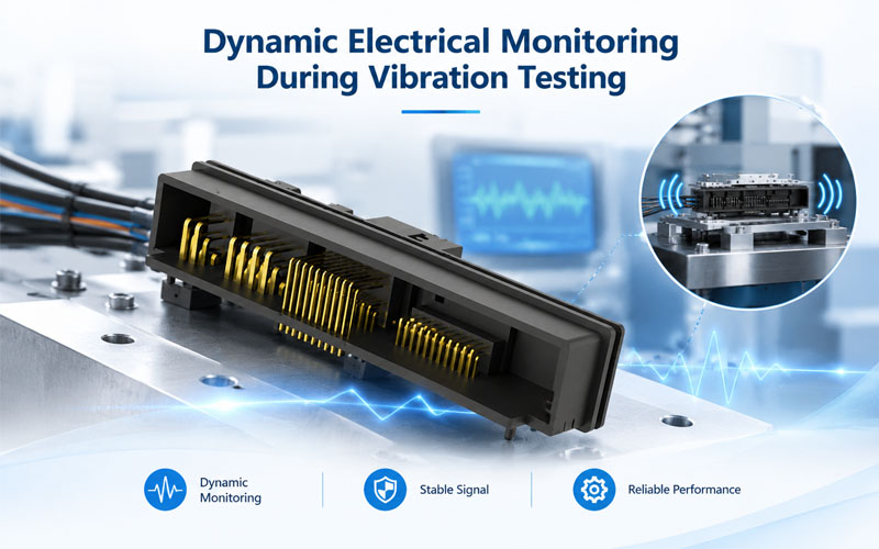
One of the most important elements of connector vibration testing is determining whether electrical interruptions occur while the connector is being excited.
A conventional continuity check performed before and after vibration provides only two snapshots of electrical performance. A brief interruption during the test may disappear once the vibration stops.
Dynamic monitoring helps reveal these events.
What should be monitored?
Depending on the application and specification, monitoring may include:
- Electrical continuity or contact disturbance
- Transient voltage changes
- Intermittent open-circuit events
- Contact resistance variation
- Signal interruptions in relevant circuits
The monitoring setup must be appropriate for the circuit under test. For example, a low-level signal circuit may require a different measurement approach from a power connection.
Understanding discontinuity events
A discontinuity is an interruption in the electrical path that meets the applicable test method’s definition of an event.
Its significance depends on factors such as event duration, circuit function, monitoring threshold, and customer acceptance requirements.
A brief interruption in a safety-critical or communication-related circuit may have different consequences from an event in another application. Therefore, engineers must not apply one universal interruption threshold to every connector.
The test plan should define the detection threshold, measurement bandwidth, permitted event duration or count, and acceptance criteria before the test begins.
Dynamic monitoring provides evidence of electrical behavior during stress rather than relying exclusively on the connector’s condition after the test.
6.What Should Be Checked After Vibration Testing?
After the vibration sequence, the connector should be evaluated against its baseline measurements and the specified acceptance criteria.
6.1 Electrical performance
Repeat the required electrical checks, which may include:
- Contact resistance
- Continuity
- Insulation resistance, where applicable
- Dielectric withstand, where required
- Circuit-specific functional checks
Any significant change should be assessed against the applicable limits rather than judged only by whether the connector still functions.
6.2 Terminal and housing condition
Inspect the assembly for:
- Terminal back-out or displacement
- Housing cracks or deformation
- Damaged locking features
- Changes in connector engagement
- Contact wear or visible damage
- Loose mounting points
- Seal displacement, where applicable
Inspection findings should be documented and linked to the relevant test sample.
6.3 Wire and termination integrity
The wire termination and harness support arrangement should also be examined.
Depending on the assembly, potential concerns include damaged insulation, wire movement at the termination, crimp-related damage, excessive bending near the connector, and stress transmitted through unsupported cable sections.
A connector may remain fully mated while damage develops elsewhere in the electrical connection system. This is why post-test inspection should include the relevant wire and mounting interfaces.
6.4 Compare results, not just pass or fail
A simple pass/fail result is necessary for acceptance, but the engineering value of testing is greater when the data are reviewed together.
For example:
- Stable continuity and resistance, with no physical damage, support the conclusion that the tested assembly met the defined criteria.
- Transient interruptions may indicate a need to investigate the contact interface, terminal positioning, mounting, or cable loading.
- A measurable resistance increase may justify additional inspection or material and contact-system analysis.
- Housing damage or terminal movement may indicate a mechanical design or assembly issue.
These observations are diagnostic clues, not proof of a single root cause. Further investigation may be required to determine the failure mechanism.
7.How Vibration Test Results Guide Connector Design Improvements
The purpose of vibration testing is not only to qualify a product. Test results can also identify opportunities to improve its design and assembly process.
Terminal and contact design
If electrical instability is detected, engineers may review terminal geometry, contact force, plating, terminal alignment, and retention features.
Any proposed change must be verified against the complete set of electrical, mechanical, and environmental requirements.
Housing and locking design
If movement or damage occurs around the connector housing, the team may evaluate locking engagement, housing support, mounting interfaces, and dimensional tolerances.
Design changes should be based on documented findings rather than assumptions about the cause.
Wire routing and strain relief
Excessive cable movement can transfer additional loads to terminals, connector housings, and mounting points.
Engineers may investigate wire length, routing, bend radius, support positions, strain relief, and the mass of the connected harness.
These changes can be particularly important when the connector is attached to a vibrating module or when a long harness applies a bending load to the interface.
Manufacturing and assembly controls
Vibration performance can also depend on production consistency.
Relevant controls may include terminal insertion, terminal position verification, crimp quality, housing assembly, locking engagement, and inspection of critical dimensions.
When a test failure is identified, the corrective action should address the confirmed cause and be verified through appropriate retesting.
8.How Standards Fit into Automotive Connector Vibration Testing
Automotive connector validation must follow the requirements applicable to the specific product and customer program.
Three useful references are:
ISO 16750-3:2023 addresses mechanical loads for road-vehicle electrical and electronic equipment. It considers environmental stresses associated with equipment mounting locations.
SAE/USCAR-2-9 specifies performance testing for applicable automotive electrical connector systems, including relevant terminals and connector components. Its scope and exclusions should be reviewed before applying it to a particular product.
IEC 60512-6-4 defines a test method for evaluating the ability of electronic components, particularly connectors, to withstand specified severities of sinusoidal vibration.
These documents are related but not interchangeable. They have different scopes and intended applications.
A connector validation plan should identify the required standard, revision, test configuration, operating conditions, sample requirements, measurement methods, and acceptance criteria. Where customer-specific requirements take precedence, those requirements must be incorporated into the approved plan.
Passing one vibration test does not automatically demonstrate compliance with every automotive connector standard or prove suitability for every vehicle installation.
9.Common Mistakes in Automotive Connector Vibration Testing
Several avoidable issues can reduce the value of a vibration test.
Relying only on pre-test and post-test continuity
This approach may miss transient electrical interruptions during vibration. Dynamic monitoring should be considered whenever required by the application or test specification.
Using an unrealistic cable arrangement
Cable length, support position, routing, and mass can influence the mechanical load applied to the connector. The setup should reflect the intended installation or the specified test configuration.
Ignoring fixture behavior
A fixture that resonates or moves unexpectedly can distort the test response. Fixture integrity and mounting conditions should be verified.
Applying generic acceptance criteria
Different connector types, circuit functions, and customer programs may have different requirements. Acceptance limits must be established from the applicable specification rather than assumed to be universal.
Treating a passing test as complete proof of reliability
Vibration testing evaluates performance under defined conditions. It does not replace other required validation activities, such as thermal cycling, mating durability, sealing evaluation, or electrical stress testing.
A robust validation plan considers the complete service environment and the relevant combination of mechanical, electrical, and environmental stresses.
How FPIC Approaches Automotive Connector Reliability
For customized automotive connector projects, reliability evaluation should begin with the intended application, operating environment, interface requirements, and customer validation criteria.
FPIC supports automotive connector development and manufacturing with attention to design requirements, terminal and housing configuration, precision production, electrical testing, and quality control.
For projects exposed to vibration, engineering reviews can consider the connector’s mounting arrangement, terminal retention, locking features, wire interface, and applicable validation requirements.
The exact test plan and acceptance criteria should be established for each project. Where specialized vibration testing is required, the testing arrangement and responsible laboratory should be confirmed as part of the validation plan.
Integrating these requirements early helps connect design decisions with measurable validation results and consistent production controls.
Conclusion
Automotive connector vibration testing evaluates whether a connection system can maintain its specified electrical and mechanical performance under defined vibration conditions.
A reliable assessment combines appropriate test profiles, representative mounting arrangements, baseline measurements, dynamic electrical monitoring where required, and detailed post-test inspection.
Most importantly, test results should be used to guide engineering decisions. By linking electrical measurements, physical inspection, and the actual application environment, engineers can identify weaknesses, verify corrective actions, and build stronger evidence for automotive connector reliability.
The goal is not simply to confirm that a connector survives a laboratory test. It is to demonstrate that the tested design meets its defined requirements under the conditions for which it was developed.
FAQ
What is automotive connector vibration testing?
It is a controlled test that exposes an automotive connector or connector assembly to specified mechanical vibration to evaluate electrical continuity, contact performance, terminal retention, mounting stability, and physical durability.
Why is dynamic continuity monitoring important during vibration testing?
Dynamic monitoring can detect brief electrical interruptions that may not be present during measurements taken before or after the test. It helps engineers evaluate electrical stability while the connector is experiencing mechanical excitation.
What is the difference between sinusoidal and random vibration testing?
Sinusoidal vibration applies controlled frequency-dependent excitation, often through a sweep or specified frequency points. Random vibration uses a defined broadband frequency profile, commonly expressed through power spectral density. The required method depends on the applicable specification and application.
Which standards are relevant to automotive connector vibration testing?
Relevant references may include ISO 16750-3 for mechanical loads on road-vehicle electrical and electronic equipment, SAE/USCAR-2 for applicable automotive electrical connector systems, and IEC 60512-6-4 for sinusoidal vibration testing of connectors. The required document and revision depend on the product and customer specification.
What should be inspected after a vibration test?
Depending on the validation plan, engineers may check contact resistance, continuity, terminal position, terminal retention, housing integrity, locking features, mounting points, wire terminations, and seals. Results should be compared with baseline data and specified acceptance criteria.
Does passing a vibration test guarantee long-term connector reliability?
No. A passing result demonstrates that the tested samples met the defined requirements under the specified conditions. Other validation activities may still be necessary to assess thermal, chemical, moisture, mating-cycle, electrical, and combined environmental stresses.
Can wire-harness design affect connector vibration performance?
Yes. Cable routing, support positions, harness mass, bend radius, and strain relief can influence the mechanical loads transmitted to the connector. The connector and its connected harness should be considered together when defining the test configuration.
Developing a custom automotive connector for a vibration-sensitive application?
FPIC supports customized automotive connector development with engineering review, precision manufacturing, and application-specific quality planning.
Share your connector configuration, installation environment, electrical requirements, and applicable validation specification to discuss a suitable development approach.
Contact FPIC to discuss your automotive connector project.
Resources
- ISO — ISO 16750-3:2023: Mechanical LoadsDescribes mechanical-load testing considerations for road-vehicle electrical and electronic equipment and its mounting locations.
- SAE International — USCAR-2-9: Performance Specification for Automotive Electrical Connector SystemsDefines performance testing requirements for applicable automotive electrical connector systems, terminals, and components.
- IEC — IEC 60512-6-4: Vibration (Sinusoidal)Specifies a test method for evaluating the ability of connectors and other applicable components to withstand defined sinusoidal vibration severities.
- FPIC — Automotive Connector Validation Process: From Design Verification to Mass ProductionRelated guidance on planning electrical, mechanical, and environmental validation for automotive connector projects.
https://fpiconn.com/automotive-connector-validation-process/
- FPIC — How Vibration Affects Automotive Connector ReliabilityCompanion article covering vibration-related failure mechanisms and their impact on long-term connector performance.
https://fpiconn.com/vibration-automotive-connector-reliability/