HVIL Connector Design: Safety Principles and Application Guide
1.Introduction: Why HVIL Matters in Electric Vehicles
Electric vehicles rely on high-voltage electrical systems to power essential components such as battery packs, traction inverters, onboard chargers, and DC-DC converters. These systems deliver the energy required for vehicle operation, but they also introduce electrical safety risks during normal operation, maintenance, and component replacement.
A conventional high-voltage connector provides a secure electrical connection between components. However, a connector’s mechanical engagement alone cannot always confirm that the connection remains fully secured or that it is safe to disconnect.
This is where the High Voltage Interlock Loop (HVIL) becomes important.
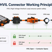
HVIL is a low-voltage monitoring circuit designed to detect the connection status of high-voltage components. When a connector is disconnected, becomes improperly engaged, or experiences a detected interlock fault, the vehicle’s safety control system can initiate an appropriate response, such as disabling high-voltage power through the designated switching and discharge strategy.
For connector manufacturers and EV system engineers, HVIL is not simply an additional signal contact. It is a coordinated safety feature involving connector geometry, contact sequencing, electrical monitoring, mechanical locking, and vehicle-level control logic.
2.What Is a High Voltage Interlock Loop?
A High Voltage Interlock Loop is an electrical monitoring circuit that checks the integrity of connections in a vehicle’s high-voltage system.
Unlike the main power contacts, which carry high current at high voltage, HVIL contacts typically operate at low voltage and low current. They form an independent monitoring path that allows the vehicle control system to identify whether designated high-voltage connections are properly engaged.
A typical HVIL system may include:
- An interlock signal source
- HVIL contacts integrated into or associated with high-voltage connectors
- Wiring that connects multiple monitored components
- A signal detection or monitoring circuit
- Vehicle control logic, often coordinated with the Battery Management System (BMS)
- High-voltage switching devices, such as contactors, used to control power delivery
Depending on the vehicle architecture, the HVIL circuit may be configured as a series loop across several components or as multiple independently monitored channels.
The monitoring system can be designed to identify conditions such as:
- Normal closed-loop operation
- Open-circuit conditions
- Short-to-ground faults
- Short-to-supply faults
- Abnormal signal levels or other diagnosed circuit faults
The exact diagnostic capability depends on the circuit architecture and monitoring electronics.
3.How Does an HVIL Connector Work?
The fundamental principle of HVIL connector design is to detect an unsafe connection condition before the main high-voltage power contacts are separated.
In a typical connector arrangement, the low-voltage interlock contacts are positioned so that their electrical connection is interrupted before the main power contacts disconnect during unplugging.
This creates a defined disconnection sequence.
3.1 Normal Connection State
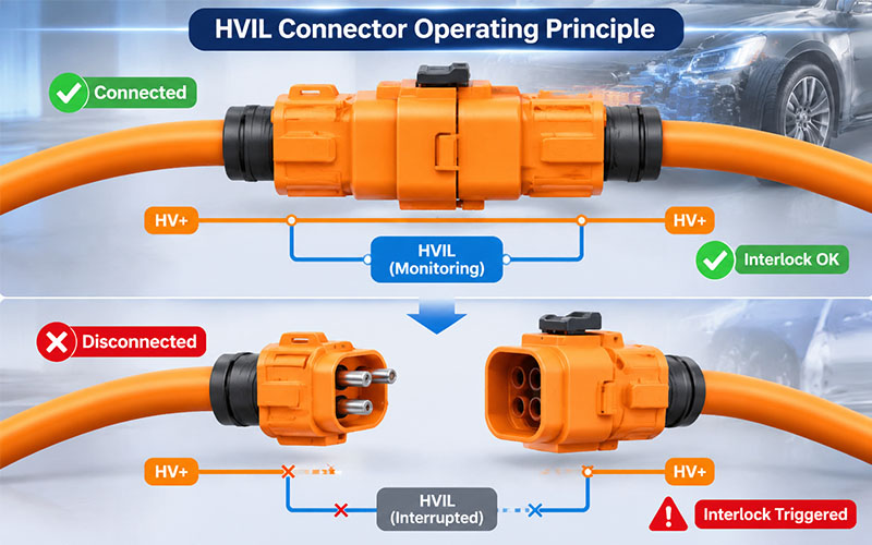
When the connector is fully mated:
- The main power contacts establish the high-voltage connection.
- The HVIL contacts complete the monitoring circuit.
- The control system detects a valid interlock signal.
- The vehicle’s high-voltage system is permitted to operate according to its safety control strategy.
The valid HVIL signal indicates that the monitored connection is in an expected state. It does not independently prove that every power contact is electrically healthy or that the entire high-voltage system is safe.
3.2 Connector Disconnection
When the connector is unplugged:
- The HVIL contacts separate first.
- The monitoring circuit detects an open or abnormal condition.
- The signal is transmitted to the relevant vehicle control system.
- The control system initiates the defined high-voltage shutdown response.
- The main power contacts separate after the interlock signal has been interrupted.
The intended result is to reduce the risk of disconnecting energized power contacts and minimize the possibility of electrical arcing.
However, the physical sequence alone does not guarantee safe disconnection. The vehicle control system must also respond within the required time, and the power circuit must reach an appropriate safe state before the main contacts separate.
4.Key Design Elements of an HVIL Connector
A reliable HVIL connector requires coordinated mechanical and electrical design. The interlock circuit must remain dependable under vibration, temperature changes, repeated mating cycles, and environmental exposure.
4.1 HVIL Contact Positioning
The position of the interlock contacts determines the disconnection sequence.
Design engineers need to establish a suitable relationship between:
- HVIL contact engagement depth
- Main power contact engagement depth
- Connector housing geometry
- Contact spring characteristics
- Mating and unmating movement
- Mechanical tolerance accumulation
The HVIL circuit should open before the main power contacts lose their required engagement.
This sequence must be maintained across manufacturing tolerances, component variation, wear, and the specified operating conditions.
4.2 Independent Low-Voltage Signal Path
The HVIL signal circuit should be electrically independent of the main high-voltage power path.
This separation helps the monitoring system detect connection status without relying on the power contacts themselves.
Important design considerations include:
- Appropriate contact insulation
- Stable low-voltage signal transmission
- Electrical isolation from high-voltage terminals
- Protection against unintended short circuits
- Reliable terminal retention
- Proper routing within the connector and cable assembly
The signal circuit should also be evaluated for electromagnetic interference and potential coupling from nearby high-current conductors.
4.3 Mechanical Locking and Connector Position Assurance
A secure mechanical connection is essential for maintaining a stable interlock signal.
Primary locking structures help prevent unintended connector separation, while Connector Position Assurance (CPA) features can provide additional confirmation that the connector has reached its intended mating position.
The design should consider:
- Primary locking strength
- CPA engagement and retention
- Housing deformation
- Terminal back-out prevention
- Connector alignment
- Resistance to vibration-induced movement
CPA and HVIL serve different functions. CPA is a mechanical assurance feature, while HVIL is an electrical monitoring function. They can complement each other but should not be treated as interchangeable safety mechanisms.
4.4 Contact Reliability and Signal Stability
Although HVIL contacts carry relatively low current, their electrical reliability remains important.
A poor contact, intermittent connection, or unstable terminal position may generate false fault signals or prevent the vehicle from recognizing a valid connection.
Relevant design factors include:
- Contact material and plating
- Contact force
- Terminal retention
- Surface condition
- Corrosion resistance
- Wear after repeated mating cycles
- Contact resistance and signal stability
The contact system should maintain reliable electrical continuity throughout its specified service life.
4.5 Housing, Sealing, and Environmental Protection
EV connectors may operate in environments exposed to moisture, dust, vibration, temperature extremes, and automotive fluids.
The connector housing and sealing system should protect both the main power contacts and the low-voltage interlock contacts.
Design considerations include:
- Housing material and thermal resistance
- Seal compression and retention
- Water and dust ingress protection
- Resistance to automotive chemicals
- Temperature cycling performance
- Mechanical durability
- Compatibility with cable insulation and overmolding materials
An ingress protection rating should be selected and validated according to the connector’s installation location and application requirements.
5.HVIL Circuit Architecture: Series Loop or Independent Monitoring?
HVIL circuit architecture affects fault detection, wiring complexity, diagnostics, and system integration.
Two common approaches are series-loop monitoring and independent channel monitoring.
5.1 Series HVIL Loop
In a series configuration, multiple interlock contacts are connected in one monitoring loop.
If any monitored connector opens the circuit, the control system detects an abnormal loop condition.
Advantages:
- Relatively simple circuit architecture
- Reduced signal-channel requirements
- Suitable for monitoring multiple connected components
- Straightforward continuity monitoring
Potential limitations:
- A fault may not immediately identify which connector caused the interruption.
- One open circuit can affect the entire loop.
- Wiring and connector layout require careful fault analysis.
- Short-circuit diagnosis depends on the monitoring circuit design.
5.2 Independent HVIL Channels
In an independent architecture, individual connectors or subsystems may have separate monitoring channels.
Advantages:
- More detailed fault localization
- Greater flexibility in system diagnostics
- Easier identification of individual subsystem conditions
- More adaptable monitoring strategies
Potential limitations:
- More complex wiring and electronics
- Additional control-system inputs
- Higher integration and validation requirements
The appropriate architecture depends on the number of high-voltage components, vehicle topology, diagnostic requirements, and functional safety strategy.
6.Common Applications of HVIL Connectors in EV Systems
HVIL is commonly used in high-voltage electrical architectures where the connection status of a component must be monitored.
6.1 Battery Pack Connections
The battery pack is one of the most important applications for HVIL.
Battery connectors and service disconnect interfaces may incorporate interlock contacts to detect disconnection or an abnormal connection state.
The monitoring system can then initiate the appropriate battery isolation strategy.
6.2 Traction Inverter Connections
The traction inverter converts DC power from the battery into AC power for the electric motor.
Its high-voltage connections must remain mechanically secure and electrically reliable. HVIL monitoring can help detect an unintended disconnection or an interlock fault in the inverter connection.
6.3 Onboard Charger Connections
The onboard charger manages the conversion of external AC power into DC power for battery charging.
HVIL monitoring may be incorporated into its high-voltage connection architecture to support safe system operation and service procedures.
6.4 DC-DC Converter Connections
The DC-DC converter transfers energy from the high-voltage system to the vehicle’s low-voltage electrical network.
Its high-voltage interfaces may also be included in the vehicle’s interlock monitoring strategy.
6.5 High-Voltage Distribution Units
High-voltage distribution units connect and distribute electrical power to multiple vehicle subsystems.
Because they may contain several high-voltage interfaces, their connector configuration and interlock architecture require careful coordination.
6.6 Service Disconnect Interfaces
Service disconnect devices are designed to support controlled isolation of high-voltage circuits during maintenance or repair
HVIL may be integrated into the service disconnect arrangement so that opening the interlock circuit initiates the designated safety response.
The actual service procedure must still follow the vehicle manufacturer’s approved high-voltage isolation and verification instructions.
7.Common HVIL Connector Design Challenges
HVIL connector design involves more than adding two low-voltage terminals to a high-voltage housing. Several engineering challenges must be addressed during development.
| Design Challenge | Potential Impact | Engineering Consideration |
|---|---|---|
| Incorrect contact sequencing | HVIL may open too late | Control contact position and tolerance stack-up |
| Unstable signal contact | Intermittent fault detection | Optimize contact force and terminal retention |
| Housing deformation | Changes in contact engagement sequence | Select suitable materials and validate mechanical strength |
| Vibration | Temporary signal interruption | Evaluate contact stability and locking performance |
| Moisture and contamination | Corrosion or electrical instability | Optimize sealing and material compatibility |
| Electromagnetic interference | Unwanted signal disturbance | Review signal routing, shielding, and circuit filtering |
| Manufacturing variation | Inconsistent connector behavior | Establish critical dimensions and process controls |
| Incomplete system coordination | Delayed shutdown response | Validate connector timing with vehicle-level control logic |
7.1 Contact Sequencing and Tolerance Stack-Up
One of the most critical challenges is maintaining the required difference between HVIL and power-contact separation.
The design must account for dimensional variation in:
- Connector housings
- Terminal positions
- Contact springs
- Seals
- Locking components
- Cable and terminal assemblies
A design that works with nominal dimensions may not maintain the intended sequence at tolerance limits.
Therefore, engineering validation should include worst-case tolerance analysis and physical testing.
7.2 False Interlock Signals
False HVIL fault signals can interrupt vehicle operation even when the main connector remains mechanically connected.
Possible causes include:
- Insufficient contact force
- Terminal movement
- Connector misalignment
- Vibration-induced intermittent contact
- Corrosion or contamination
- Damaged interlock wiring
A robust design should minimize these risks while allowing the monitoring circuit to identify genuine faults.
7.3 Integration with Vehicle Safety Logic
HVIL connector performance cannot be evaluated independently of the vehicle’s control system.
The complete safety response depends on signal detection, fault diagnosis, controller processing, contactor operation, and the electrical characteristics of the high-voltage system.
The connector supplier and vehicle system engineer should define the relevant interface requirements early in the development process.
8.HVIL Connector Testing and Validation
Validation should cover both the physical connector and its role within the interlock system.
The specific test plan should be based on the connector specification, vehicle architecture, customer requirements, and applicable standards.
8.1 Electrical Continuity Testing
Verify that the HVIL signal path maintains stable electrical continuity when the connector is correctly mated.
The test should also identify intermittent contact behavior and abnormal resistance.
8.2 Contact Sequencing Verification
Confirm that the HVIL circuit opens before the main power contacts separate during unplugging.
Testing should account for relevant dimensional tolerances and connector operating conditions.
Where required, evaluate both mating and unmating sequences.
8.3 Mechanical Durability Testing
Evaluate the connector’s ability to maintain reliable mechanical and electrical performance after:
- Repeated mating and unmating cycles
- Vibration exposure
- Mechanical shock
- Cable pull and strain loading
- Locking and retention assessments
The HVIL signal should remain stable under the specified conditions.
8.4 Environmental Testing
Depending on the application, environmental validation may include:
- High- and low-temperature exposure
- Temperature cycling
- Humidity exposure
- Water and dust ingress testing
- Salt spray or corrosion testing
- Chemical compatibility testing
After environmental exposure, the connector should be checked for housing damage, seal deterioration, contact corrosion, and changes in interlock signal performance.
8.5 Fault Detection Testing
The complete monitoring circuit should be tested under defined fault conditions.
These may include:
- Open circuit
- Short to ground
- Short to supply
- Intermittent connection
- Abnormal signal resistance
- Wiring damage
The test should verify whether the monitoring electronics correctly recognize the specified fault conditions and generate the expected diagnostic response.
8.6 System-Level Shutdown Response
A connector-level test cannot fully establish the safety performance of the vehicle.
System-level validation should confirm that an HVIL fault is detected and that the vehicle control system initiates the required high-voltage shutdown sequence.
Relevant factors include:
- Fault detection time
- Control-system response time
- Contactor opening behavior
- Residual voltage and discharge strategy
- Main power-contact separation timing
- Diagnostic reporting
This step is essential because the effectiveness of HVIL depends on the complete electrical and control architecture.
9.Standards and Engineering References
HVIL design should be evaluated within the broader electrical safety and connector engineering framework.
Several standards and technical references may be relevant:
ISO 6469-3:2021 — Electrically Propelled Road Vehicles: Electrical Safety
This standard specifies electrical safety requirements for voltage Class B electric circuits in electrically propelled road vehicles. It provides an important vehicle-level safety reference, although it is not a dedicated HVIL connector design specification.
SAE USCAR-12 — Wiring Component Design Guidelines
USCAR-12 provides connector and wiring design guidance, including considerations for high-voltage applications. Its design guidance should be used alongside the applicable performance specifications and customer requirements.
SAE J1742 — High-Voltage On-Board Vehicle Electrical Wiring Connections
SAE J1742 provides test methods and general performance requirements for high-voltage on-board vehicle electrical connection systems within its defined scope.
Texas Instruments TIDA-020069 — Automotive High-Voltage Interlock Loop Reference Design
This technical reference demonstrates an HVIL monitoring architecture, including signal generation, fault detection, and diagnostic handling. It is useful for understanding how the connector-level interlock circuit interacts with vehicle electronics.
An important distinction: these documents do not establish one universal HVIL connector pinout, contact sequence, signal voltage, or diagnostic threshold for every EV platform. OEM specifications and system-level safety requirements determine the final design.
10.Design Considerations for HVIL Connector Customization
For customized automotive high-voltage connectors, HVIL requirements should be considered during the initial design stage rather than added after the main connector structure is finalized.
A structured engineering review should include the following areas.
Electrical Requirements
- Main circuit voltage and current ratings
- HVIL signal voltage and current
- Contact resistance requirements
- Electrical isolation requirements
- Signal integrity and fault-detection strategy
Mechanical Requirements
- Connector mating and unmating direction
- HVIL contact positioning
- Power-contact sequencing
- Primary locking and CPA design
- Terminal retention
- Cable exit direction and strain relief
Environmental Requirements
- Operating temperature range
- Vibration and mechanical shock conditions
- Ingress protection requirements
- Corrosion resistance
- Chemical compatibility
- Expected service life
Manufacturing Requirements
- Terminal stamping and forming consistency
- Contact plating control
- Housing dimensional accuracy
- Assembly process control
- Electrical continuity inspection
- Contact-position and locking verification
- Product traceability
Engineering collaboration between the connector manufacturer, cable assembly supplier, and vehicle system team helps reduce design changes during validation and production ramp-up.
For customized projects, prototype evaluation should confirm the connector’s mechanical engagement, interlock signal behavior, and compatibility with the vehicle’s control architecture before mass production.
11.How to Select an HVIL Connector Manufacturer
Selecting an HVIL connector manufacturer requires more than comparing current ratings, dimensions, and unit prices.
A capable supplier should demonstrate experience in both high-voltage connector engineering and precision manufacturing.
Key evaluation criteria include:
- Automotive quality management: Relevant quality systems and customer-specific requirements.
- High-voltage connector experience: Knowledge of insulation, terminal design, sealing, and mechanical locking.
- HVIL integration capability: Ability to develop and manufacture connector structures with dedicated interlock contacts.
- Engineering support: Support for drawings, dimensional reviews, prototype development, and design optimization.
- Testing capability: Electrical, mechanical, and environmental verification appropriate to the application.
- Manufacturing consistency: Controlled terminal processing, assembly, inspection, and traceability.
- Mass-production readiness: Stable processes, quality documentation, and production capacity.
FPIC supports automotive connector manufacturing and customized connector development, with engineering and production processes focused on dimensional consistency, electrical performance, and quality control. For projects involving HVIL integration, connector requirements should be reviewed against the customer’s electrical architecture and validation specification.
12.Conclusion
HVIL is an important safety feature in electric vehicle high-voltage architectures. By monitoring the connection status of high-voltage components, it allows the vehicle control system to respond when an interlock circuit becomes open or abnormal.
Reliable HVIL connector design depends on several coordinated factors: contact sequencing, independent signal paths, mechanical locking, stable electrical contact, environmental protection, and system-level fault response.
For EV manufacturers and connector suppliers, the most effective approach is to integrate HVIL requirements into the connector design from the beginning and validate the complete connection system under realistic operating conditions.
As electric vehicle platforms continue to evolve, well-engineered HVIL interfaces will remain an important part of dependable high-voltage connection systems.
FAQ
What does HVIL stand for in electric vehicles?
HVIL stands for High Voltage Interlock Loop. It is a low-voltage monitoring circuit used to detect the connection status of designated high-voltage components in electric vehicles.
What is the main function of an HVIL connector?
An HVIL connector provides an interlock signal path that allows the vehicle control system to monitor whether the connector is properly engaged. When the circuit opens or an abnormal condition is detected, the system can initiate its designated high-voltage safety response.
Why does the HVIL contact disconnect before the main power contact?
The HVIL contact is designed to open first so that the vehicle control system can detect the disconnection and initiate high-voltage shutdown before the main power contacts separate. This helps reduce the risk of electrical arcing during disconnection.
Is HVIL the same as CPA?
No. CPA (Connector Position Assurance) is a mechanical feature that helps confirm connector engagement and prevent unintended separation. HVIL is an electrical monitoring circuit that detects connection status. Both can be used together in automotive connector designs.
Does every EV high-voltage connector require HVIL?
Not necessarily. HVIL requirements depend on the vehicle architecture, connector application, OEM safety strategy, and applicable specifications. Some high-voltage interfaces use other safety or monitoring arrangements.
What tests are important for HVIL connectors?
Important evaluations may include electrical continuity, contact sequencing, contact resistance, mating durability, vibration, environmental exposure, fault detection, and system-level shutdown response.
Can HVIL be integrated into a customized high-voltage connector?
Yes. HVIL contacts can be integrated into a customized connector design. However, contact positioning, electrical isolation, mechanical engagement, signal routing, and vehicle-level control requirements must be considered together.
Looking for a Customized Automotive High-Voltage Connector with HVIL Integration?
The right connector design starts with a clear understanding of your electrical, mechanical, and safety requirements.
FPIC provides automotive connector manufacturing and customized development support for applications requiring reliable electrical connections and controlled production quality.
Contact our engineering team to discuss your connector drawings, technical specifications, and project requirements.
Resources
- Texas Instruments — Automotive High-Voltage Interlock Loop (HVIL) Reference Design, TIDA-020069
- Texas Instruments — TIDA-020069 Reference Design Overview
- ISO — ISO 6469-3:2021, Electrical Safety for Electrically Propelled Road Vehicles
- SAE International — USCAR-12 Wiring Component Design Guidelines
- SAE International — J1742 High-Voltage On-Board Vehicle Electrical Wiring Connections