Why Fretting Corrosion Happens in Automotive Connectors
1.Introduction
Automotive connectors must maintain reliable electrical contact despite vibration, temperature changes, and years of service. Yet a connector can remain fully mated and appear undamaged while its electrical performance gradually deteriorates.
One possible cause is fretting corrosion—a contact degradation process associated with repeated, small relative movements between mating surfaces. These movements can wear the contact finish and generate debris. In susceptible material systems, oxidation and the accumulation of surface films can increase contact resistance and cause intermittent electrical faults.
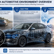
Fretting corrosion is especially important in automotive electrical systems because connectors may experience multiple interacting stresses. Road-induced vibration, differences in thermal expansion, cable movement, contact-force changes, and surface wear can all contribute to the degradation process. Research on automotive connectors has documented fretting-related damage and its relationship with increased electrical contact resistance. [1] [2]
Understanding this mechanism helps engineers distinguish fretting-related degradation from other connector failures and select appropriate design, manufacturing, and validation measures.
2.What Is Fretting Corrosion?
Fretting corrosion occurs when contacting surfaces experience repeated small-amplitude relative movement, resulting in wear and, where the materials and environment permit, chemical degradation of the contact interface.
In an electrical connector, the mating terminal surfaces are held together by contact force. Ideally, the interface maintains sufficient electrically conductive contact areas throughout the required operating conditions.
However, vibration or thermal movement may cause the two surfaces to shift slightly relative to one another. Repeated movement can damage the surface finish, remove material, and generate wear particles. For susceptible non-noble-metal finishes, these particles may oxidize and accumulate in the contact region.
The resulting surface films and debris can interfere with conductive contact spots, making contact resistance unstable or higher than permitted.
Three related terms are useful:
- Fretting motion: Repeated small relative movement between contacting surfaces.
- Fretting wear: Material loss and surface damage caused by that repeated movement.
- Fretting corrosion: Degradation involving fretting wear and corrosion-related surface changes.
These terms are related but not interchangeable. Fretting motion can produce mechanical wear, while the severity and electrical consequences depend on the contact materials, plating system, force, environment, and movement conditions.
3.How Fretting Corrosion Develops in Automotive Connectors
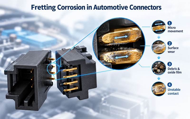
Fretting corrosion is usually a progressive process rather than a single event.
Stage 1: Small relative movement begins
The connector remains mated, but the contact surfaces move slightly against each other. The movement may be associated with vehicle vibration, mechanical loading, or differential thermal expansion.
The movement at the contact interface can differ from the vibration measured at the connector housing. Contact geometry, fixture stiffness, cable support, and structural response all influence how much movement reaches the mating surfaces.
Stage 2: The contact finish begins to wear
Repeated movement produces friction at the interface. Depending on the material pair and contact conditions, the surface finish may become worn, displaced, or damaged.
If a protective coating becomes locally thinner or wears through, the underlying layer or base material may become exposed. A noble-metal finish can also experience fretting damage if its coating is breached.
Stage 3: Debris and surface films accumulate
Wear particles may remain within the contact region. When susceptible materials are exposed to oxygen, oxidation can contribute to the formation of surface films with poorer electrical conductivity than the intended contact finish.
The details depend on the plating system. For example, tin-based contact finishes can develop oxide-related degradation, while damaged gold-plated contacts may expose less corrosion-resistant underlayers or substrate materials.
Stage 4: Conductive contact becomes less stable
As the interface degrades, the effective conductive contact area may change. The contact resistance can become unstable or increase beyond the permitted limit.
This does not necessarily happen at a constant rate. Contact force, movement amplitude, temperature, plating condition, and debris behavior can influence when electrical degradation becomes significant.
Stage 5: Electrical symptoms appear
Depending on the circuit and severity, the connector may exhibit:
- Intermittent electrical continuity
- Unstable contact resistance
- Unexpected voltage drop
- Localized heating under current load
- Signal disturbance or communication errors
- An electrical fault that appears only under certain vibration or temperature conditions
A connector may pass a static continuity check after the vehicle stops moving even though intermittent interruptions occurred during operation. Dynamic monitoring can therefore be important when investigating suspected fretting-related faults.
4.What Causes Fretting Corrosion in Automotive Connectors?
Fretting corrosion is generally associated with interacting mechanical, material, electrical, and environmental factors. No single factor explains every failure.
4.1 Vehicle vibration and mechanical excitation
Vehicle operation exposes connectors to vibration from road surfaces, powertrain systems, and other vibrating components.
Even when the connector housing remains securely locked, small movements may occur at the electrical contact interface. The actual risk depends on the connector structure, mounting arrangement, contact force, cable support, and frequency-dependent mechanical response.
The important engineering question is not simply whether the connector vibrates, but whether that vibration produces damaging relative movement at the mating contacts.
4.2 Thermal expansion and contraction
Automotive connectors can experience repeated temperature changes during operation and environmental exposure.
Different materials may expand and contract at different rates. This differential movement can contribute to small shifts at the contact interface, especially when combined with mechanical constraints or temperature-dependent changes in material properties.
Thermal cycling can therefore contribute to fretting even when external vibration is not the only or dominant source of motion.
4.3 Insufficient or declining contact force
Contact force helps maintain the mating interface and can influence how sensitive the connection is to small movements.
If the initial contact force is inadequate, or if it decreases through stress relaxation, deformation, wear, or other mechanisms, the interface may become more susceptible to instability.
However, simply increasing contact force is not a universal solution. Excessive force can increase mating effort, mechanical stress, and wear. The target should be a validated force range appropriate to the contact design and service environment.
4.4 Plating material and wear resistance
The plating system influences how the interface responds to repeated movement.
Tin is widely used in electrical contacts but can be susceptible to fretting-related resistance degradation under certain conditions. Gold can provide corrosion-resistant contact surfaces, but it is not immune to fretting if the coating wears through or becomes damaged.
Performance depends on more than the name of the plating material. Relevant factors include:
- Plating thickness and coverage
- Underplate material
- Hardness and wear resistance
- Contact force and geometry
- Mating surface compatibility
- Lubrication, where specified and appropriate
- Environmental exposure
The finish should be selected and qualified for the actual application rather than assuming one material is always superior.
4.5 Wire harness movement and inadequate support
A connector’s attached harness can transfer mechanical loads to the terminal system.
If cable movement is not adequately controlled, bending moments and other loads may reach the connector and influence relative contact motion. Cable routing, free length, support location, strain relief, and harness mass can all affect the dynamic behavior of the assembly.
For this reason, connector fretting should not always be investigated as an isolated contact-material problem. The surrounding harness and mounting arrangement may be important contributors.
4.6 Miniaturization and limited design margin
Compact connector systems have less space for contact structures and may use smaller spring elements.
Depending on the design, miniaturization can constrain contact geometry, available spring deflection, plating thickness options, and heat dissipation. This does not mean smaller connectors inevitably suffer more fretting corrosion, but it can make careful control of contact force, tolerances, and surface performance especially important.
5.Why Fretting Corrosion Can Increase Contact Resistance
Electrical current passes through the microscopic regions where the mating contact surfaces actually conduct. The apparent contact area is larger than the sum of these real conductive contact spots.
As fretting damage develops, wear, surface films, and changes in contact force can reduce or destabilize the effective conductive regions. The result may be increased or fluctuating electrical contact resistance.
For a current-carrying connection, resistive heating follows:
[P=I^2R]
Where (P) is the power dissipated as heat, (I) is current, and (R) is resistance.
For illustration, a resistance of 1 mΩ at 50 A produces 2.5 W of resistive heating at that resistance. If the resistance increases to 2 mΩ at the same current, the calculated dissipation becomes 5 W.
These calculations illustrate why resistance changes can matter in power circuits. They do not predict the actual connector temperature, which also depends on heat transfer, terminal geometry, conductor size, ambient temperature, and operating conditions.
In signal circuits, a different concern may dominate: a brief interruption or resistance fluctuation can disturb a signal even when the average current is low.
Therefore, the electrical impact of fretting corrosion depends on the connector’s function, not just the magnitude of its measured resistance.
6.How to Identify Fretting Corrosion
A suspected fretting-related failure should be investigated systematically. An increase in contact resistance alone does not prove fretting corrosion, because oxidation, contamination, loss of contact force, plating defects, and other mechanisms can produce similar symptoms.
6.1 Review the failure conditions
Start by documenting when the fault occurs.
- Useful questions include:
- Does the fault appear during vibration or road operation?
- Does it correlate with temperature changes?
- Does the electrical symptom disappear when movement stops?
- Is the problem isolated to one circuit or observed across several contacts?
- Has the connector experienced repeated mating, service, or environmental exposure?
These observations help determine which tests and inspections are most useful.
6.2 Measure contact resistance
Measure contact resistance using a suitable method and compare the results with baseline measurements and the applicable specification.
For low-resistance interfaces, a four-wire Kelvin measurement can reduce the influence of lead and connection resistance. If the suspected failure is intermittent, a static measurement may not be sufficient.
Dynamic electrical monitoring during vibration or controlled movement may reveal interruptions or resistance changes that would otherwise be missed.
6.3 Inspect the contact surfaces
After recording the initial electrical evidence, inspect the mating contacts for signs such as:
- Localized wear or polishing
- Plating loss or exposed underlayers
- Discoloration or accumulated debris
- Surface damage in the contact region
- Asymmetric wear patterns
Visual inspection can suggest a mechanism but may not establish it conclusively. Surface appearance must be interpreted alongside electrical measurements and the contact’s service history.
6.4 Use microscopy and material analysis when necessary
For difficult or high-impact failures, additional analysis may be needed.
Depending on the case, methods can include optical microscopy, scanning electron microscopy (SEM), elemental analysis such as energy-dispersive X-ray spectroscopy (EDS), and plating cross-section examination.
These techniques can help distinguish wear, coating loss, oxidation, and other surface degradation mechanisms. The selection and sequence of tests should consider which methods are nondestructive and which may alter the sample.
6.5 Reproduce the failure under controlled conditions
If necessary, use an application-relevant test setup to reproduce the suspected conditions. Vibration, thermal cycling, contact loading, and harness support may need to be considered together.
The objective is to establish a defensible relationship between the observed failure and the operating conditions, rather than relying on appearance alone.
7.How to Reduce Fretting Corrosion in Automotive Connectors
Fretting-related degradation can often be mitigated by controlling relative motion, maintaining appropriate contact force, selecting suitable contact finishes, and validating the complete connector assembly.
7.1 Optimize contact geometry and force
The contact structure should maintain sufficient force throughout the specified operating range without creating excessive mating force or mechanical stress.
Design reviews should consider spring geometry, material properties, tolerances, contact alignment, and the effects of temperature.
Contact force should be measured and verified against the design requirements, especially when the connector is miniaturized or exposed to demanding environmental conditions.
7.2 Select a suitable plating system
The contact finish should match the required electrical performance, environmental exposure, mating frequency, and expected mechanical movement.
Review the full plating system, including thickness, underplate, wear behavior, and manufacturing controls. A change from tin to gold, for example, should not be treated as an automatic fix without checking compatibility, wear conditions, and application requirements.
7.3 Reduce unwanted relative movement
Where feasible, reduce mechanical loads reaching the contact interface.
Potential measures include:
- Improving connector mounting stability
- Optimizing harness routing and support
- Controlling cable free length near the connector
- Adding appropriate strain relief
- Reviewing connector and harness resonance behavior
- Avoiding unnecessary loads on the mating interface
These measures should be based on the actual assembly and its dynamic behavior. Over-constraining a harness or changing its support without engineering review can transfer stress to another location.
7.4 Consider contact lubrication only when qualified
Specialized contact lubricants may reduce friction and wear in some contact systems. However, compatibility depends on the contact materials, plating, electrical function, sealing system, temperature range, and manufacturing process.
Lubrication should only be used when approved for the connector design and validated for the intended application. It is not a universal remedy and should not replace proper contact geometry or mechanical support.
7.5 Maintain plating and forming process control
Manufacturing consistency is essential to achieving the intended contact performance.
Relevant controls may include:
- Plating thickness and coverage
- Contact beam dimensions
- Forming accuracy
- Surface condition
- Terminal alignment
- Contact force
- Terminal retention
- Crimp and assembly quality
The critical characteristics should be identified during design and controlled throughout production.
8.How to Validate Resistance to Fretting-Related Degradation
Validation should evaluate the connector under conditions that reflect the intended vehicle application and the applicable customer specification.
A practical validation plan may include the following stages.
Stage 1: Define the operating environment
Establish vibration conditions, temperature range, current or signal requirements, connector mounting, harness routing, and relevant service conditions.
Stage 2: Record baseline performance
Measure initial contact resistance and other required electrical and mechanical characteristics. Document the sample configuration and test setup.
Stage 3: Apply the specified stress
Conduct the relevant vibration, thermal cycling, or combined environmental testing. The test severity and duration must be based on the applicable specification rather than a universal fretting threshold.
Stage 4: Monitor electrical behavior
Where the risk and test method justify it, monitor continuity or contact resistance dynamically during exposure. Define the detection threshold and acceptance criteria before testing.
Stage 5: Perform post-test inspection
Repeat the required electrical measurements and inspect the contact surfaces, plating, terminal position, and connector structure.
Stage 6: Investigate and verify corrective actions
If degradation is found, establish the likely root cause and confirm that the proposed corrective action addresses it. Retesting should follow the approved validation plan.
The objective is to demonstrate that the connector meets its specified performance requirements—not to claim that any single test can eliminate all future fretting risk.
9.Common Misconceptions About Fretting Corrosion
Misconception 1: A locked connector cannot experience fretting
A locking mechanism helps prevent connector separation, but it does not guarantee zero relative movement at every contact interface. Mechanical response depends on the complete connector and harness assembly.
Misconception 2: Gold-plated contacts cannot suffer fretting damage
Gold can reduce certain corrosion-related risks, but repeated movement can wear through a thin or damaged finish. The exposed underlying material may then degrade.
Misconception 3: Any increase in contact resistance proves fretting corrosion
Contact resistance can rise for several reasons. Diagnosis should combine electrical measurements, physical inspection, service history, and, where necessary, material analysis.
Misconception 4: Increasing contact force always solves the problem
Contact force can influence stability, but excessive force may increase mating effort, wear, and mechanical stress. The design requires a validated balance.
Misconception 5: A connector that passes a static continuity test is reliable under vibration
A static test may not capture brief interruptions that occur only during mechanical excitation. Dynamic monitoring may be needed to investigate intermittent faults.
How FPIC Supports Automotive Connector Reliability
Automotive connector reliability depends on coordinated decisions across contact design, materials, manufacturing, harness integration, and validation.
FPIC supports customized automotive connector development and manufacturing, with attention to terminal configuration, precision production, electrical testing, and quality control.
For applications exposed to vibration or thermal cycling, an engineering review can consider the operating environment, contact system, connector mounting, harness support, and relevant customer validation requirements.
A clear definition of the application and its acceptance criteria helps connect design decisions with measurable test results and consistent production controls.
Conclusion
Fretting corrosion develops when repeated small movements degrade the mating contact interface. Depending on the materials and conditions, wear, surface-film formation, and coating damage can destabilize electrical contact and increase resistance.
In automotive connectors, vibration, thermal movement, contact-force changes, plating wear, and harness loading may contribute to this process. Effective prevention therefore requires more than changing the plating material or increasing contact force.
The most reliable approach combines suitable contact design, a qualified surface finish, controlled mechanical movement, consistent manufacturing, and application-specific validation.
By investigating electrical symptoms alongside physical evidence, engineers can identify the underlying degradation mechanism and select corrective actions that address the actual cause of the failure.
FAQ
What is fretting corrosion in automotive connectors?
Fretting corrosion is a degradation process associated with repeated small relative movements between mating contact surfaces. Wear and, in susceptible material systems, oxidation-related surface films can increase or destabilize electrical contact resistance.
What causes fretting corrosion in automotive connectors?
Common contributing factors include vehicle vibration, differential thermal expansion, inadequate or declining contact force, plating wear, and mechanical loads transmitted through the attached harness. The dominant mechanism varies by design and operating conditions.
Can gold-plated automotive connectors experience fretting corrosion?
Yes. Gold offers useful corrosion resistance, but repeated movement can wear through the coating or damage the plating system. If underlying materials become exposed, contact degradation may occur.
How can engineers distinguish fretting corrosion from other connector failures?
A structured investigation can combine contact-resistance measurements, dynamic continuity monitoring, surface inspection, microscopy, and material analysis where appropriate. Increased resistance alone is not sufficient to confirm fretting corrosion.
How does fretting corrosion affect contact resistance?
Repeated movement can damage the contact finish and produce wear debris or surface films. These changes can reduce or destabilize conductive contact regions, resulting in higher or fluctuating resistance.
Can connector lubrication prevent fretting corrosion?
A suitable, qualified lubricant may reduce friction and wear in some contact systems. Compatibility with the contact materials, plating, electrical function, environment, and production process must be verified before use.
Which tests help evaluate fretting-related connector degradation?
Depending on the application, tests may include contact-resistance measurement, dynamic continuity monitoring, vibration testing, thermal cycling, mating durability, and post-test surface analysis. The methods and acceptance criteria should follow the applicable product and customer requirements.
Investigating intermittent electrical faults in an automotive connector?
FPIC supports customized automotive connector development with engineering review, precision manufacturing, electrical testing, and quality-focused production planning.
Share your connector configuration, operating environment, and observed failure symptoms to discuss a suitable engineering approach.
Contact FPIC to discuss your automotive connector project.
Resources
- Song, Hilmert and Kiel — Mechanisms of Failure and State Analysis of Electrical Connectors in Automobiles
A research paper examining automotive connector degradation, including fretting corrosion, contact resistance changes, coating wear, and failure-analysis methods.
- IPC — IPC-TM-650, Test Method 3.16: Fretting Corrosion, Connectors
Describes a test method for assessing the susceptibility of non-noble-metal contact interfaces to fretting corrosion through controlled relative movement and contact-resistance measurements.
https://www.electronics.org/sites/default/files/test_methods_docs/3-16.pdf
- Sumitomo Electric — Deterioration Analysis of Automotive Connectors Used in High Mileage Vehicles
Discusses field-related automotive connector degradation and the role of repeated small movements, wear particles, oxidation, temperature cycling, and vibration.
https://sumitomoelectric.com/sites/default/files/2020-12/download_documents/81-02.pdf
- Swingler — The Automotive Connector: The Influence of Powering and Lubricating a Fretting Contact Interface
Research on how electrical loading and lubrication influence fretting behavior at automotive connector contact interfaces.
- Antler — Contact Fretting of Electronic Connectors
A technical review of fretting mechanisms, contact resistance instability, material effects, and potential mitigation approaches for electrical connectors.
https://globals.ieice.org/en_transactions/electronics/10.1587/e82-c_1_3/_p


 FPIC