Why Connector Coupling Mechanisms Matter
Threaded, bayonet, and push-pull locking in industrial equipment
Two connectors can have similar current and voltage ratings yet behave differently when an installer reaches into a crowded machine or a technician replaces a module. Connector coupling mechanisms help explain that difference: they determine how the halves engage, stay secured, and release.
Connector coupling mechanisms hold the connector halves in their intended operating position. Its design affects mating motion, resistance to unintended separation, and service access. Reliability depends on the complete connector assembly and its verified operating conditions.
The useful question is how a particular design will work in your equipment. Installation clearance, cable loading, vibration, sealing, and maintenance frequency all belong in that review.
What the Locking Mechanism Actually Controls
The coupling system secures the connector halves. Inside the connector, the contacts provide the conductive interface; contact retention features secure individual terminals; cable clamps or other strain-relief features manage loads entering through the cable.
These functions interact, but they are different. A coupling ring can remain locked while another part of the assembly has a problem. Likewise, a successful continuity check does not tell an installer whether the locking operation is complete.
LEMO’s technical overview describes locking as the mechanical means of securing the mating halves and explains that the choice depends on the application and environment. [1]
For a design review, ask three separate questions:
- Can the operator achieve and recognize complete engagement?
- Does the assembly remain mechanically and electrically acceptable under its specified loads?
- Can a technician disconnect it using the available access and approved procedure?
A drawing that shows only the installed envelope answers none of these questions completely.
Threaded Coupling: Controlled Engagement with Access Requirements
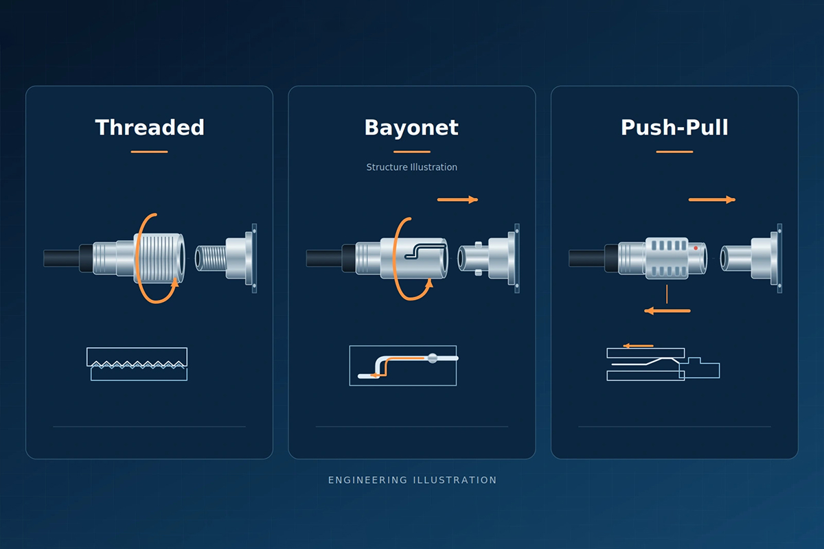
A threaded circular connector uses mating threads to bring and hold the halves together. Many designs use a rotating coupling nut, allowing the installer to operate the nut while maintaining the connector body’s orientation.
Check the specified mating procedure for the exact model. The required rotation, final position, and any tightening torque belong to that interface. The torque for a panel mounting nut or cable gland is a separate requirement.
For equipment integration, the main trade-off is access. An operator needs room to reach and rotate the coupling element. A connection that is easy to tighten on a workbench may be awkward behind an adjacent cable bundle. Include the actual connector spacing and required tools in a mock-up.
Vibration performance also depends on details beyond the presence of threads. Amphenol’s Dualok literature, for example, describes an additional anti-decoupling mechanism intended for severe vibration service. That illustrates why engineers should inspect the locking design and its qualification evidence rather than assume every threaded connection behaves alike. [2]
Design review: confirm how full mating is established, what prevents unintended loosening, and whether the required operation remains practical after the equipment is fully assembled.
Bayonet Locking: Short Rotation with a Defined Final Position
Bayonet systems typically guide pins or lugs through matching tracks and retain them at the end of a limited rotational movement. The actual angle and locking arrangement depend on the connector family; “bayonet” does not mean every design uses the same quarter-turn motion.
This can provide a convenient sequence for equipment connections: align, engage, rotate, and confirm the final position. Inspect how the chosen design indicates completion and what maintains engagement. A partial turn must not be mistaken for a completed locking operation.
The UPT family brochure describes a metal bayonet coupling on a plastic-shell connector, while Amphenol’s MGT-5015 product information describes a reverse-bayonet family intended for demanding shock and vibration applications. These examples demonstrate the variety within the category; their ratings apply to their respective products. [3][4]
Design review: check rotational clearance, visibility of the final position, the approved release action, and the effect of wear or contamination on the mechanism. Short travel alone does not establish resistance to vibration.
Push-Pull Self-Locking: Axial Operation and Release Access
A push-pull self-locking connector can engage through an axial push and release through a deliberate action on a sleeve or other designated element. LEMO’s description of its original system distinguishes pulling the release sleeve from pulling the cable. [1]
This operating motion can be useful where repeated service connections make rotating a coupling nut inconvenient. However, the equipment still needs space to grip the release element and withdraw the plug. Nearby panels, labels, boots, and adjacent connectors can obstruct that action.
During layout review, identify exactly which surface a technician must hold. Also check whether surrounding objects could act on the release element unintentionally. A compact connector does not automatically create a serviceable installation.
Distinguish self-locking designs from breakaway designs, which intentionally separate under a defined pulling load. Both can use an axial motion, but they serve different requirements. [1]
Design review: evaluate engagement, release, and withdrawal in the actual installation. Use the specified component and test conditions to establish retention and durability.
Comparing the Three Approaches
The table below is a design-review framework, not a ranking or a substitute for product specifications.
| Review point | Threaded coupling | Bayonet locking | Push-pull self-locking |
|---|---|---|---|
| Operating motion | Rotate the threaded coupling element | Engage and rotate through the designed locking travel | Push to engage; operate the designated release to disconnect |
| Space to evaluate | Nut access, rotation, and any required tool | Grip and rotational clearance | Release access and axial withdrawal clearance |
| Completion check | Specified position and torque or other stated criterion | Specified final position and locking indication | Specified latch engagement and confirmation method |
| Frequent maintenance | Assess total tightening and release time | Assess alignment, turning, and confirmation time | Assess gripping, release, and withdrawal time |
| Vibration review | Loosening control and complete assembly test | Locking track, retention features, and complete assembly test | Latch retention, release exposure, and complete assembly test |
| Sealing review | Exact seals, assembly method, and rated condition | Exact seals, assembly method, and rated condition | Exact seals, assembly method, and rated condition |
For rectangular machine interfaces, lever-locked heavy-duty connectors introduce another operating motion. Include the lever sweep and hood-removal space in the layout review. They should not be treated as a variant of circular bayonet locking simply because both offer a short manual operation.
What the Amphenol UPT Announcement Shows
Amphenol’s October 8, 2026 announcement introduces a UPT 12 Pin configuration and emphasizes installation and serviceability alongside electrical and environmental characteristics. That makes it a relevant example of manufacturers addressing the mechanical aspects of connector selection. [5]
There is a documentation detail to resolve: as reviewed on October 14, the group announcement describes a triple-start ACME thread, while the linked industrial-division announcement describes bayonet coupling. The current UPT product page also describes bayonet coupling. [5][6][7]
For a design-in decision, confirm the exact part number, drawing revision, and mating instructions with the manufacturer before classifying this new configuration. The public wording does not support treating the two descriptions as interchangeable.
The practical lesson is to compare actual mating geometry and operating instructions. A product-family name or a short launch announcement may not supply enough detail to specify the interface.
Vibration Resistance Requires More than a Locked Shell
Three observations deserve separate attention during an application review: unintended release of the coupling, movement within the assembly, and electrical disturbances during operation.
Mechanical retention helps maintain the intended interface position. It does not, by itself, quantify the electrical behavior of the contacts under dynamic loading. A useful validation plan therefore considers both the mechanical condition and the required electrical measurements.
IEC 60512-6-4 covers a sinusoidal vibration test for connectors, as identified in the DIN standards listing. That method title does not establish a product’s test severity or acceptance limits. Those still need to come from the applicable specification and agreed test plan. [8]
Recommended questions for the test review include:
- Which vibration profile, axes, duration, and mounting arrangement represent the application?
- What cable length, routing, mass, and support arrangement will the sample use?
- Will the test monitor electrical interruptions, and with what detection criteria?
- What mechanical, contact-resistance, and functional checks follow the exposure?
- Does the test sequence need to include prior mating cycles or environmental conditioning?
These are planning questions. They do not prescribe a universal test sequence. A shipping-vibration assessment should not automatically serve as evidence for continuous vibration beside a motor.
Sealing Depends on the Complete Assembly
The coupling mechanism helps maintain the geometry required by the sealing design. The seals, cable entry, panel interface, materials, and installation procedure determine the protection achieved by the assembled product.
LEMO’s sealing guidance describes the combination of mechanical design and gaskets and distinguishes situations requiring protection when connected from those requiring protection when disconnected. [9]
For an industrial application, review the specified condition explicitly:
- Does the rating apply when mated, unmated, or fitted with a protective cap?
- Which cable diameter, gland, seal, and mounting arrangement does it cover?
- What installation steps establish the required seal compression?
- Which cleaning fluids, oils, temperatures, or washdown conditions need separate evaluation?
An IP designation is evidence for the stated ingress test conditions. It does not by itself establish chemical compatibility, indefinite immersion capability, or performance after an unspecified maintenance history.
Do not increase tightening torque beyond the manufacturer’s instructions in an attempt to improve sealing. Investigate the correct seal and assembly condition instead.
Measure Maintenance Access and Total Connection Time
For this comparison, a practical engineering approach is to time the whole service operation: identify the interface, reach it, align the halves, complete engagement, verify the condition, and route the cable correctly.
A quick locking movement may contribute little if most of the time goes into access or alignment. Conversely, a connector that takes longer to operate may remain appropriate for an interface rarely disconnected.
Use a representative machine mock-up to compare candidates. Recommended trial conditions include the intended gloves, adjacent connectors, cable boots, visibility, and available tools. Record unsuccessful attempts and ambiguous completion indications as well as elapsed time.
Maintenance also includes cleaning, inspection, contact replacement where permitted, and protection of exposed interfaces. Ask which components can be serviced, which tools are needed, and which seals or parts require replacement after disassembly.
The useful outcome is an operating procedure that a technician can repeat in the installed equipment.
A Practical Validation Checklist
Before releasing the connector selection, create a comparison record for each exact plug–receptacle combination.
| Item | Evidence to request or establish |
|---|---|
| Interface identity | Part numbers, keying, contact arrangement, compatible accessories, and drawing revisions |
| Mating procedure | Alignment, operating sequence, torque or force where specified, and completion indication |
| Mechanical retention | Approved load directions, fixture, acceptance criteria, and condition of the locking parts |
| Electrical stability | Relevant resistance and interruption checks under the agreed operating conditions |
| Environmental protection | Rated assembly state, seals, cable entry, panel installation, and applicable test reports |
| Durability | Required mating cycles, maintenance instructions, and post-test acceptance criteria |
| Service access | Installed-space trial covering connection, release, withdrawal, and tool access |
Use these records to identify gaps before committing the enclosure layout. When a configuration changes, review which results remain applicable. A new cable gland, seal material, shell, or release mechanism can change the assembly that the original evidence describes.
Applying the Review to an FPIC Project
FPIC’s circular connector range includes threaded and push-pull options. Its R&D and quality assurance resources support structural review, material selection, and project-specific verification. For custom equipment interfaces, the relevant work is to connect those choices with the actual installation envelope and service procedure.
For an OEM/ODM engineering review, share the interface drawing, electrical requirements, vibration and sealing conditions, expected service frequency, and available access space with info@fpiconn.com. Define the validation scope around the selected configuration.
Frequently Asked Questions
Are threaded connectors always better for vibration?
No. Compare the exact locking design and applicable test evidence. Threaded, bayonet, and self-locking push-pull products can serve demanding applications, but the mechanism name alone does not establish their performance under your vibration profile.
Is a bayonet connector always a quarter-turn connector?
No. Rotation and locking geometry vary by family. Use the selected product’s drawing and instructions to determine the required movement and final locking position.
Can a push-pull connector be released by pulling the cable?
For a self-locking design, use the specified release element and procedure. Do not confuse that behavior with a breakaway connector designed to separate at a defined load, and do not treat cable pulling as a universal release method.
Does the locking style determine the IP rating?
No. Ingress protection depends on the complete sealing design and the specified assembled condition. Confirm whether the rating requires mating, a cap, a particular cable gland, or a specific mounting arrangement.
Which design is best for frequent maintenance?
Choose after testing the installed service operation. Grip access, alignment, release clearance, cycle durability, and inspection requirements can matter as much as the speed of the locking motion.
Can two connectors with similar ratings replace each other?
Similar electrical ratings are insufficient. Verify interface compatibility, keying, contact arrangement, mounting, locking, sealing, cable termination, and relevant test evidence before approving a substitution.
Resources
- LEMO — Locking Systems. Locking function, axial self-latching operation, release sleeves, and breakaway distinction.
- Amphenol Aerospace — Dualok Data Sheet. Example of an additional anti-decoupling design for vibration service; no performance equivalence to FPIC is implied.
- Amphenol Industrial — UPT Connector Series Brochure. Metal bayonet coupling in the documented UPT family; not independent confirmation of every new configuration.
- Amphenol Aerospace — MGT-5015 Reverse Bayonet Coupling. Product-specific example of a bayonet family for demanding environments.
- Amphenol — Product News, UPT 12 Pin announcement, October 8, 2026. Group announcement containing the triple-start ACME description.
- Amphenol Industrial — UPT Series 12 Pin Expansion. Linked announcement containing the bayonet description.
- Amphenol Industrial — UPT Connector Series. Current family page; exact configuration details require confirmation where descriptions differ.
- DIN Media — DIN EN 60512-6-4:2003-01. Official listing of the connector sinusoidal vibration method based on IEC 60512-6-4:2002; the full standard was not used to prescribe a test procedure here.
- LEMO — Watertightness & Hermeticity. Sealing design and connected/disconnected protection requirements.