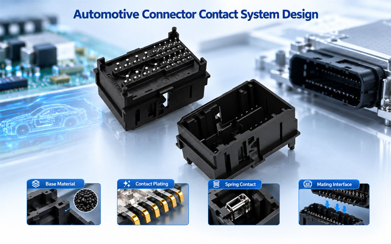
Automotive Connector Contact System Design: Materials and Performance
1. Introduction
Automotive connector provide electrical interfaces for sensors, control modules, lighting systems, infotainment equipment, and many other vehicle electronics. Although the connector housing and locking mechanism are important, the contact system is responsible for transferring current or signals between mating components.
Its performance depends on several interacting design elements: conductive materials, contact geometry, spring characteristics, surface plating, and the mechanical conditions at the mating interface.
A contact with high electrical conductivity may still perform poorly if it cannot maintain sufficient contact force. A corrosion-resistant plating system may wear prematurely if the contact geometry creates excessive friction. Likewise, a mechanically robust terminal may generate excessive heat if the complete current path has inadequate electrical performance.
Reliable automotive contact system design is therefore a balance of electrical, mechanical, thermal, environmental, and manufacturing requirements—not simply a choice of metal.
This guide examines the key design variables, explains how different material systems affect performance, and outlines a practical approach to contact system selection and validation.
2.What Is an Automotive Connector Contact System?
A contact system consists of the conductive elements and mating interface that establish an electrical connection.
Depending on the connector architecture, it may include:
- Contact or terminal base material: Provides electrical conductivity and mechanical strength.
- Spring contact structure: Maintains the force required for stable mating contact.
- Contact plating: Controls surface behavior, corrosion protection, wear, and electrical interface performance.
- Mating interface geometry: Determines how contacts engage and distribute force.
- Terminal-to-wire termination: Connects the contact system to the conductor through a crimp, weld, or another specified termination method.
- Retention features: Keep terminals correctly positioned within the connector housing.
These elements perform different functions but must work together.
For example, the mating interface may have suitable initial resistance, yet terminal deformation or loss of spring force can reduce contact stability over time. Similarly, good contact performance cannot compensate for an inadequate wire termination or poor terminal retention.
A complete design should evaluate the entire electrical path, from the wire termination through the terminal body and mating interface to the opposing contact.
3.Selecting Contact Base Materials
The base alloy determines much of a contact’s electrical and mechanical behavior. Material selection should consider conductivity, strength, elastic recovery, stress relaxation, fatigue resistance, stamping capability, and cost.
3.1 Brass
Brass is a copper-zinc alloy commonly used in connector terminals and electrical contact components.
Its potential advantages include:
- Good manufacturability and formability for suitable grades
- Practical electrical conductivity
- Compatibility with established stamping and forming processes
- Broad availability and cost-effective production
Brass may be suitable for contacts where its mechanical and electrical characteristics meet the application requirements.
However, not every brass grade provides the same conductivity or spring performance. For designs requiring sustained elastic force, engineers must verify the selected alloy and temper rather than relying on the generic material name.
3.2 Phosphor bronze
Phosphor bronze is a copper-based alloy used in many spring-contact applications.
It offers a useful combination of electrical conductivity, strength, formability, and spring behavior, depending on the specific grade and temper.
Potential applications include:
- Spring contacts
- Female terminal structures
- Signal and control interfaces
- Compact contact systems requiring stable elastic behavior
The main design consideration is the balance between conductivity and mechanical performance. Alloy composition, material thickness, forming geometry, and heat treatment can all influence the final properties.
Phosphor bronze should therefore be selected according to the required force-deflection behavior, current capacity, operating temperature, and expected mechanical life.
3.3 High-strength copper alloys
Some automotive contact designs require greater spring strength, improved stress relaxation resistance, or enhanced fatigue performance.
Specialized copper alloys may be considered when conventional materials cannot meet the combined requirements.
Selection factors include:
- Conductivity under the specified electrical load
- Yield strength and elastic recovery
- Stress relaxation at elevated temperature
- Resistance to repeated deflection
- Stamping and forming feasibility
- Material and processing cost
Higher strength does not automatically mean better overall performance. A material with excellent spring characteristics may have lower conductivity than another candidate. The contact geometry and thermal design must account for this trade-off.
3.4 Comparing common contact materials
| Material family | Potential advantages | Important design considerations |
|---|---|---|
| Brass | Manufacturability, formability, practical conductivity | Grade-dependent strength and spring behavior |
| Phosphor bronze | Balanced conductivity and spring properties | Alloy grade, temper, force retention, fatigue |
| Specialized copper alloys | Higher strength or improved stress relaxation for selected designs | Conductivity, cost, forming process, application suitability |
The values and behavior of specific alloys vary. Final selection should use material datasheets, supplier specifications, and testing of the actual contact design.
4.Contact Plating: Engineering the Mating Surface
The base alloy provides the structural foundation, but the plating system directly affects the surface where current transfers between mating contacts.
Plating can influence corrosion resistance, wear, contact stability, and the durability of the electrical interface. The appropriate finish depends on the signal or power application, environmental exposure, mating cycles, and contact force.
4.1 Tin plating
Tin is commonly used in cost-sensitive automotive electrical interfaces, including many power and general-purpose connections.
Its suitability depends on the contact geometry and operating conditions.
Engineers should consider:
- Contact force and wiping action
- Surface oxide behavior
- Expected mating frequency
- Vibration and relative contact movement
- Environmental exposure
- Plating thickness and process consistency
Tin-plated contacts need a suitable interface design to maintain stable performance. The presence of tin alone does not establish a connector’s current rating or service life.
4.2 Gold plating
Gold is used where surface corrosion resistance and stable low-level electrical contact are important.
It may be considered for sensitive signal interfaces, selected high-cycle applications, and environments where surface degradation could affect performance.
Design factors include:
- Gold thickness and hardness
- Underplate selection
- Contact force
- Mating cycles
- Wear at the contact interface
- Cost and plating coverage
Gold plating is not automatically the best choice for every automotive connector. The appropriate system depends on the actual interface requirements and validated performance.
4.3 Silver plating
Silver has high electrical conductivity and may be used in selected power and high-current contact systems.
However, its suitability depends on the operating environment, surface condition, contact design, and applicable performance requirements.
Environmental exposure and surface-film formation should be considered during material selection and qualification.
4.4 Underplating and plating thickness
The contact finish may contain multiple layers rather than a single surface coating.
A typical system may include:
Base Alloy → Underplate → Functional Contact Finish
The underplate can support corrosion protection, reduce unwanted diffusion between layers, and help stabilize the plating system, depending on the selected materials and process.
Plating specifications should identify the relevant layer materials, thickness requirements, plated areas, and inspection methods.
Where necessary, methods such as X-ray fluorescence (XRF) measurement and metallographic cross-section analysis can help verify plating thickness and layer structure.
The critical point is that plating material, thickness, coverage, and mating-interface design must be evaluated together. A material name alone is not a complete plating specification.
5.Contact Geometry and Spring Force
Contact geometry determines how mating terminals engage, how force is distributed, and how the contact structure responds to mechanical and thermal loading.
Depending on the design, contacts may use cantilever beams, dual-beam structures, box-style receptacles, or other spring geometries.
5.1 Maintaining sufficient contact force
Contact force helps maintain the physical interface between mating surfaces despite small dimensional variations and operational movement.
If force is insufficient, the interface may become more sensitive to vibration, contamination, surface-film effects, and changes in contact resistance.
However, increasing force without considering the complete design can create other problems:
- Higher mating and unmating forces
- Greater wear during repeated connection cycles
- Increased stress on the spring structure
- More difficult automated assembly
- Reduced serviceability
The objective is not to maximize force. It is to maintain the specified force range throughout the intended service conditions.
5.2 Elastic range and stress relaxation
A spring contact must operate within a suitable elastic range.
If the contact is permanently deformed during mating or assembly, its ability to maintain the intended force may be reduced.
Elevated temperature can also cause stress relaxation in some materials, gradually reducing spring force under sustained deflection.
Engineers should therefore consider:
- Maximum and minimum deflection
- Material yield behavior
- Contact beam dimensions
- Forming tolerances
- Operating temperature
- Long-term force retention
These factors become especially important in compact connectors, where limited space can make spring geometry more sensitive to manufacturing variation.
5.3 Wiping action and surface wear
Some contact designs create relative sliding movement during mating. This wiping action can help establish a reliable interface by moving across surface films or minor contamination.
However, excessive wiping distance or force can increase friction and plating wear.
The design should balance interface cleaning, contact stability, mating force, and plating durability.
The suitable geometry depends on the finish system, contact materials, environmental conditions, and expected number of mating cycles.
6.Electrical Performance and Thermal Behavior
The contact system must carry the specified current or transmit signals without unacceptable electrical degradation.
For power connections, contact resistance is closely related to heat generation.
The basic relationship is:
[P=I^2R]
Where:
- (P) is the electrical power dissipated as heat.
- (I) is the current through the contact.
- (R) is the relevant electrical resistance.
For illustration, a resistance of 1 mΩ at 50 A produces 2.5 W of resistive heating at that resistance.
This calculation illustrates why resistance control matters, but it does not establish the temperature rise or current rating of a real connector. Actual thermal performance also depends on heat transfer, terminal geometry, conductor size, ambient temperature, neighboring loaded circuits, and mounting conditions.
Design implications
A contact system should be evaluated for:
- Resistance across the complete intended current path
- Current distribution through the contact geometry
- Temperature rise under defined operating conditions
- Resistance stability after mechanical and environmental exposure
- Thermal interaction with adjacent terminals and housing materials
A highly conductive base alloy cannot compensate for poor mating geometry, inadequate contact force, or a degraded surface interface.
Likewise, a connector that performs well at room temperature may require additional evaluation at its specified operating temperature.
Current ratings should therefore be based on the connector’s validated specifications and applicable derating requirements—not on material conductivity alone.
7.Matching Contact Materials to Automotive Applications
Different automotive circuits place different demands on the contact system.
7.1 Low-level signal and sensor circuits
Signal circuits may be sensitive to small changes in interface condition, intermittent contact, and electrical noise.
Selection priorities can include:
- Stable contact behavior at low signal levels
- Suitable plating and corrosion protection
- Consistent contact force
- Dimensional accuracy
- Resistance to vibration-related degradation
The appropriate finish depends on signal characteristics, environmental conditions, and the connector’s mating requirements.
7.2 Power distribution circuits
Power connections place greater emphasis on current capacity, resistance, and temperature rise.
Important considerations include:
- Conductivity and contact cross-section
- Stable contact force
- Heat dissipation
- Surface finish compatibility
- Terminal and wire termination performance
- Performance under the specified continuous or intermittent load
Material selection should be supported by electrical and thermal validation under representative conditions.
7.3 Compact and high-density connectors
Miniaturized connectors must maintain reliable contact behavior within limited dimensions.
Design challenges may include:
- Reduced terminal spacing
- Smaller spring structures
- Tight dimensional tolerances
- Restricted heat dissipation
- Greater sensitivity to terminal alignment
- Manufacturing consistency at fine pitch
A suitable material must support both the required electrical performance and the mechanical properties needed in the available geometry.
7.4 Vibration-exposed automotive interfaces
Connectors exposed to vibration must maintain stable mating engagement and electrical performance under the specified mechanical loads.
Relevant design factors include spring-force retention, terminal locking, plating durability, contact geometry, and the mechanical load transmitted by the connected harness.
Material selection alone cannot eliminate vibration-related failure. The complete connector assembly and its mounting arrangement must be evaluated through appropriate testing.
8.Manufacturing Factors That Affect Contact System Performance
A well-designed contact system must also be manufactured consistently.
Material properties and geometry can be affected by stamping, forming, plating, assembly, and inspection processes. Variation at any stage may influence the final interface.
8.1 Stamping and forming
Critical characteristics may include:
- Contact beam dimensions
- Bend angles and radii
- Spring height
- Surface condition
- Burr direction and size
- Dimensional consistency
These characteristics can affect mating force, alignment, contact pressure, and the risk of premature wear.
8.2 Plating process control
Plating quality depends on more than the specified material.
Relevant controls may include surface preparation, plating thickness, coverage, adhesion, and consistency across the functional contact area.
The inspection method and acceptance limits should be defined by the product specification and validated manufacturing process.
8.3 Assembly and terminal positioning
During assembly, terminals must be inserted and retained correctly.
Incorrect positioning can affect mating engagement and may prevent the contact system from operating as intended.
Where applicable, terminal position assurance (TPA) features and suitable assembly inspections can help control terminal seating.
8.4 Design for manufacturability
Material selection should be reviewed alongside production feasibility.
Engineers should consider whether the selected alloy can be stamped and formed consistently, whether the plating process can meet the specified requirements, and whether critical characteristics can be inspected at production volume.
A contact system is successful only when its required performance can be reproduced consistently across manufacturing batches.
9.How to Validate an Automotive Connector Contact System
Validation should connect design requirements to measurable results.
The test plan must reflect the intended application, relevant customer specifications, and the connector’s operating environment.
Step 1: Define application requirements
Establish the electrical load, signal characteristics, temperature range, environmental exposure, mating cycles, and mechanical conditions.
Step 2: Review the material and interface design
Confirm the base alloy, temper, plating system, contact geometry, force requirements, and dimensional tolerances.
Step 3: Measure initial electrical and mechanical performance
Depending on the specification, measurements may include contact resistance, mating force, unmating force, terminal retention, and dimensional inspection.
Step 4: Conduct application-relevant validation
Potential tests include:
- Temperature rise under specified electrical loading
- Temperature cycling
- Vibration and mechanical shock
- Mating durability
- Corrosion or environmental exposure
- Contact resistance after conditioning
- Relevant insulation or dielectric tests for the complete connector
Not every test applies to every design. The required sequence, severity, sample size, and acceptance criteria should follow the approved validation plan.
Step 5: Inspect and compare results
Compare pre-test and post-test measurements, inspect contact surfaces where appropriate, and document any deviation from the defined requirements.
If a failure occurs, use the evidence to investigate the likely mechanism before selecting corrective actions.
Step 6: Verify production consistency
Design validation should be complemented by controls for the manufacturing characteristics that influence performance, including terminal geometry, plating, forming, assembly, and inspection.
This helps establish that the qualified design can be reproduced consistently in mass production.
10.Common Mistakes in Contact System Design
Selecting materials based on conductivity alone
Electrical conductivity is important, but the material must also provide suitable spring properties, fatigue resistance, and manufacturability.
Treating plating as a standalone solution
A corrosion-resistant finish cannot compensate for inadequate contact force, unsuitable geometry, or excessive mechanical movement.
Increasing contact force without considering mating requirements
Excessive force can increase insertion effort, wear, and mechanical stress. The target should be a validated operating range.
Specifying plating without defining thickness and coverage
A plating specification should identify the functional layers and relevant acceptance criteria, not simply state “gold plated” or “tin plated.”
Ignoring manufacturing variation
Small changes in spring height, bend geometry, plating thickness, or terminal position can influence contact behavior. Critical characteristics should be controlled throughout production.
Validating only the initial electrical condition
Initial measurements do not demonstrate long-term performance under vibration, temperature changes, mating cycles, or environmental exposure. Validation should reflect the relevant service conditions.
How FPIC Supports Automotive Connector Development
Automotive connector projects require coordination between electrical requirements, contact geometry, material selection, manufacturing feasibility, and validation planning.
FPIC supports customized automotive connector development and manufacturing, with attention to product requirements, terminal and housing configuration, precision production, electrical testing, and quality control.
For a new project, an engineering review can consider the intended application, connector dimensions, contact arrangement, electrical load, environmental conditions, and applicable customer requirements.
The objective is to align the contact system with the intended application and the production process from the beginning, rather than relying on material selection alone to achieve reliability.
Conclusion
Automotive connector contact system design depends on the interaction between base alloy, plating, spring geometry, contact force, electrical loading, and manufacturing consistency.
Brass, phosphor bronze, and specialized copper alloys can each be appropriate for different designs. Tin, gold, and silver finishes also serve different requirements, depending on the contact interface and operating environment.
The best solution is not necessarily the material with the highest conductivity, the hardest spring, or the most expensive plating. It is the combination that meets the required electrical and mechanical performance throughout the intended service conditions and can be manufactured consistently.
By connecting material selection with geometry, process control, and application-specific validation, engineers can develop automotive connector contact systems with a stronger basis for long-term performance.
FAQ
What materials are commonly used for automotive connector contacts?
Common options include brass, phosphor bronze, and other copper alloys. The final selection depends on conductivity, spring behavior, fatigue resistance, temperature exposure, forming requirements, and cost.
Is gold plating always better than tin plating for automotive connectors?
No. Gold may be appropriate for certain low-level signal interfaces and applications requiring specific corrosion or wear performance. Tin is widely used in many general-purpose and power connections. The correct finish depends on the application, contact geometry, mating requirements, and validation results.
How does contact force affect automotive connector performance?
Contact force helps maintain a stable interface between mating terminals. Insufficient force can increase sensitivity to movement and surface degradation, while excessive force can increase mating effort, wear, and mechanical stress.
Why does contact geometry matter?
Geometry determines how the mating contacts engage, distribute force, and respond to mechanical loading. It also influences current distribution, wear behavior, mating force, and the consistency of the electrical interface.
How can engineers verify contact system performance?
Depending on the application, validation may include contact resistance, mating force, terminal retention, temperature rise, vibration, temperature cycling, mating durability, and corrosion testing. The required methods and acceptance criteria should follow the applicable specification.
Does a highly conductive contact material guarantee a high current rating?
No. Current capacity depends on the complete design, including contact resistance, geometry, terminal cross-section, heat dissipation, ambient conditions, and the number of simultaneously loaded circuits. Ratings must be established through appropriate testing and derating.
What should a contact plating specification include?
It should identify the plating material, layer structure where applicable, thickness requirements, functional coverage, inspection method, and acceptance criteria. The specification should reflect the intended mating interface and operating environment.
Developing a customized automotive connector for your application?
FPIC supports OEM and engineering teams with customized connector development, precision manufacturing, electrical testing, and quality-focused production planning.
Share your connector configuration, electrical requirements, environmental conditions, and project specifications to discuss a suitable development approach.
Contact FPIC to discuss your automotive connector project.
Resources
- Würth Elektronik — Trilogy of Connectors: Basic Principles of Connectors
Engineering reference covering connector materials, contact finishes, copper alloys, and plating processes.
- SAE International — ARP6903A: Guide for Achieving Plating/Finishing Compatibility
Guidance on selecting compatible finishes and platings for connectors and electrical wiring interconnection systems, with consideration of corrosion compatibility.
- KYOCERA — Contact (Terminal) and Its Materials
Overview of common contact materials and the relationship between copper alloys, conductivity, and spring characteristics.
- FPIC — How Connector Plating Affects Performance and Lifetime
Related guidance on plating materials, surface protection, thickness, and connector service life.
https://fpiconn.com/how-connector-plating-affects-performance-and-lifetime/
- FPIC — How Contact Geometry Influences Connector Reliability
Companion article covering how contact geometry influences mating behavior, electrical performance, and mechanical reliability.
https://fpiconn.com/how-contact-geometry-influences-connector-reliability/