How Contact Geometry Influences Connector Reliability
A connector is only as reliable as its contact system.
Although the external housing provides protection and mechanical support, the actual electrical connection happens at the contact interface.
The design of this small area determines whether a connector can maintain stable performance under:
- High current loads
- Vibration
- Temperature changes
- Repeated mating cycles
- Harsh operating environments
For applications such as automotive electronics, industrial automation, robotics, energy storage systems, and medical equipment, contact geometry plays a critical role in connector reliability.
A well-designed connector does not simply make contact.
It maintains consistent electrical and mechanical performance throughout its service life.
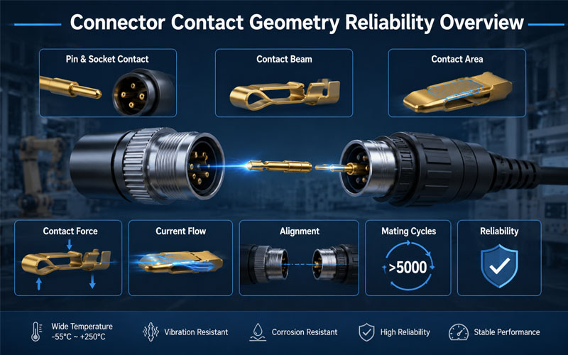
What Is Connector Contact Geometry?
Contact geometry refers to the physical design of the connector contact interface.
It includes:
- Contact shape
- Contact beam structure
- Contact area
- Contact engagement position
- Contact pressure distribution
- Wiping action during mating
The goal of contact geometry design is to achieve the right balance between:
- Electrical conductivity
- Mechanical strength
- Contact stability
- Mating durability
Different applications require different contact structures.
A high-current power connector and a high-speed signal connector may use completely different contact geometries because their performance requirements are different.
Why Contact Geometry Is Critical for Connector Reliability
When two connector contacts mate, several physical factors determine connection quality.
A reliable contact interface must provide:
Stable Electrical Path
Ensuring current can flow efficiently with minimal resistance.
Proper Contact Force
Maintaining connection stability without excessive mechanical stress.
Controlled Wear
Allowing repeated mating without rapid degradation.
Resistance to Environmental Stress
Maintaining performance against:
- Vibration
- Shock
- Temperature variation
- Corrosion
Poor contact geometry can result in:
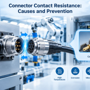
- Increased contact resistance
- Intermittent electrical connection
- Signal interruption
- Excessive heat generation
- Premature connector failure
1.Contact Shape Determines Connection Performance
The shape of the contact element directly affects current transmission and mechanical stability.
Common contact structures include:
Pin and Socket Contacts
Pin and socket designs are widely used in circular connectors and industrial connectors.
Advantages:
✔ Reliable alignment
✔ Stable contact interface
✔ Good environmental adaptability
The socket contact usually uses spring structures to maintain contact pressure around the pin.
This design helps compensate for:
- Manufacturing tolerance
- Vibration
- Mechanical movement
Blade Contacts
Blade contacts provide a larger conductive path.
Advantages:
✔ High current capability
✔ Simple structure
✔ Good mechanical strength
They are commonly used in:
- Power connectors
- Automotive applications
- Industrial equipment
Spring Contacts
Spring-based contacts use elastic deformation to maintain continuous pressure.
Advantages:
✔ Improved vibration resistance
✔ Stable contact force
✔ Longer service life
They are suitable for applications requiring frequent mating cycles.
2.Contact Force Affects Reliability and Mating Performance
Contact force is one of the most important design parameters.
The correct contact force ensures:
- Stable electrical connection
- Low contact resistance
- Resistance to vibration
However, both insufficient and excessive force can create problems.
Too Low Contact Force
Potential issues:
- Increased electrical resistance
- Intermittent connection
- Signal instability
Low contact force may allow micro-movement between contacts, causing electrical degradation over time.
Too High Contact Force
Potential issues:
- Higher insertion force
- Increased contact wear
- Reduced mating cycles
A good connector design balances:
Contact Reliability + User Operation + Service Life
3.Contact Area Influences Current Flow and Heat Generation
The contact interface determines how efficiently electrical current transfers between mating components.
A well-designed contact area helps:
- Reduce current concentration
- Lower resistance
- Minimize heat generation
However, contact area alone does not determine performance.
Engineers must also consider:
- Contact pressure
- Surface condition
- Material properties
- Contact alignment
A larger contact surface without proper pressure control may not provide better reliability.
4.Wiping Action Helps Maintain Clean Contact Surfaces
Many connector designs include wiping action during mating.
During insertion, the contact surfaces slide against each other.
This movement helps remove:
- Dust particles
- Surface oxidation
- Minor contamination
Benefits include:
✔ Improved electrical stability
✔ Reduced contact resistance variation
✔ Better long-term reliability
Wiping action is especially important for:
- Outdoor equipment
- Industrial automation
- High-cycle connectors
5.Contact Geometry Determines Mating Cycle Life
Every mating cycle creates mechanical stress on contacts.
Repeated connection and disconnection can cause:
- Surface wear
- Loss of contact force
- Material deformation
A reliable contact design considers:
Contact Elasticity
Maintains pressure after repeated use.
Wear Resistance
Reduces surface damage.
Mechanical Stability
Prevents deformation during operation.
For connectors requiring thousands of mating cycles, optimized contact geometry is essential.
6.Alignment Design Prevents Contact Damage
Even a well-designed contact can fail if alignment is poor.
Incorrect alignment may cause:
- Bent pins
- Uneven contact pressure
- Partial engagement
- Contact damage
Reliable connector systems often include:
- Polarization features
- Guide structures
- Mechanical keys
- Alignment sleeves
These features ensure correct mating and protect the contact system.
7.Contact Geometry Influences Thermal Reliability
Electrical resistance generates heat.
When contact geometry is poor, current may concentrate in small areas, creating:
- Hot spots
- Temperature rise
- Contact degradation
A properly designed contact structure improves:
- Current distribution
- Heat dissipation
- Long-term stability
This is especially important for:
- High-current connectors
- Battery systems
- Industrial power equipment
8.Contact Geometry Must Match Application Requirements
Different industries require different contact solutions.
| Application | Contact Design Priorities |
|---|---|
| Automotive | Vibration resistance, durability, stable contact force |
| Robotics | High mating cycles, mechanical stability |
| Industrial Automation | Environmental protection, reliability |
| Energy Storage | High current capability, thermal control |
| Medical Equipment | Stable signal transmission, safety |
Connector design should always begin with understanding the actual application environment.
9.Contact Material and Plating Work Together with Geometry
Contact geometry is only one part of connector reliability.
Material selection and surface treatment are equally important.
Contact Material
Common materials include:
- Copper alloys
- Brass
- Phosphor bronze
Important characteristics:
- Electrical conductivity
- Spring performance
- Mechanical strength
Contact Plating
Gold Plating
Advantages:
✔ Excellent corrosion resistance
✔ Low contact resistance
✔ Long mating life
Suitable for:
- Signal connectors
- Precision applications
Tin Plating
Advantages:
✔ Cost-effective
✔ Suitable for many power applications
Suitable for:
- General electrical connections
10.How FPIC Optimizes Connector Contact Design
FPIC focuses on connector reliability through:
Precision Contact Engineering
Including:
- Contact structure optimization
- Contact force control
- Mechanical tolerance management
Material and Plating Selection
Considering:
- Current requirements
- Environment
- Mating cycles
Reliability Testing
Including:
- Contact resistance testing
- Insertion and extraction force testing
- Mating cycle evaluation
- Environmental testing
Through engineering optimization and manufacturing control, FPIC helps customers develop reliable connector solutions for demanding applications.
Common Contact Geometry Design Mistakes
| Design Mistake | Potential Result |
|---|---|
| Incorrect contact force | Intermittent connection |
| Poor alignment design | Contact damage |
| Insufficient contact area | Heat generation |
| Weak wiping action | Increased resistance |
| Improper material selection | Reduced service life |
Contact Geometry Design Checklist
Before finalizing a connector design, engineers should evaluate:
✔ Is the contact force within the correct range?
✔ Can the contact maintain stability after repeated mating?
✔ Is current distribution optimized?
✔ Does the geometry support the application environment?
✔ Are material and plating choices appropriate?
✔ Has the design been validated through testing?
Final Thoughts
Contact geometry is one of the most important factors influencing connector reliability.
A reliable connector requires careful optimization of:
- Contact shape
- Contact force
- Contact area
- Alignment
- Material selection
- Surface treatment
The contact interface may be small, but it determines the overall performance of the connector system.
A connector is not reliable because it connects once.
It is reliable because it maintains a stable connection thousands of times under real-world conditions.
FAQ
What is contact geometry in connectors?
Contact geometry refers to the physical structure and design of the electrical contact interface, including shape, contact area, and pressure distribution.
How does contact geometry affect connector reliability?
It affects electrical resistance, current flow, mating durability, vibration resistance, and long-term performance.
Why is contact force important in connector design?
Proper contact force ensures stable electrical connection while balancing insertion force and wear.
Can contact geometry affect connector temperature?
Yes. Poor contact geometry can increase resistance and create localized heat generation.
How do engineers improve connector contact reliability?
Engineers optimize contact structure, materials, plating, alignment, and validate performance through reliability testing.
Need a Reliable Custom Connector Solution?
FPIC provides custom connector design and manufacturing services with expertise in contact engineering, material selection, reliability testing, and mass production.
From concept development to final production, FPIC helps OEM customers build connectors designed for long-term performance.
Contact FPIC today to discuss your connector requirements.
Resources
- IEC 60512 – Connectors for Electronic Equipment – Tests and Measurements
https://www.iec.ch/
Connector testing methods covering electrical and mechanical performance evaluation. - EIA-364 Connector Test Standards
https://www.eia-global.org/
Industry test standards for connector reliability and performance validation. - IPC/WHMA-A-620 – Requirements and Acceptance for Cable and Wire Harness Assemblies
https://www.ipc.org/
Industry acceptance criteria for cable and wire harness assemblies.