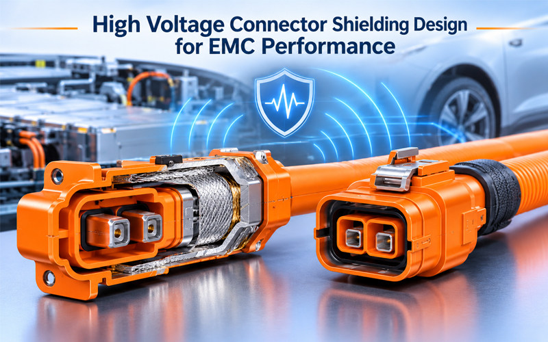
High Voltage Connector Shielding Design for EMC Performance
1.Introduction
Electric vehicles rely on high-voltage electrical systems to transfer power between battery packs, inverters, electric motors, onboard chargers, and other electrical components. These systems operate with high currents and rapidly changing electrical conditions, creating electromagnetic disturbances that can affect nearby electronic equipment.
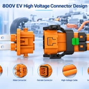
High voltage connectors are an important part of this electromagnetic compatibility (EMC) system. They must provide reliable electrical power transmission while maintaining effective shielding continuity between the cable, connector, and equipment housing.
Poor shielding connections can create gaps in the conductive path, increase electromagnetic leakage, and allow unwanted interference to enter or leave the high-voltage system.
For this reason, high voltage connector shielding should be considered during the early stages of connector and cable assembly development—not simply treated as an additional metal component.
This article explores the main shielding design principles, common engineering challenges, and validation methods used to improve EMC performance in high-voltage connector systems.
2.Why EMC Shielding Matters in High Voltage Connectors
EMC refers to the ability of electrical and electronic equipment to operate correctly in its electromagnetic environment without generating unacceptable electromagnetic disturbances.
In electric vehicles, high-voltage power electronics can generate electromagnetic noise through switching operations, current changes, and other electrical activities. This interference may couple into nearby circuits through conductive paths or electromagnetic fields.
High-voltage connector shielding helps manage these disturbances by providing a controlled conductive path around the power conductors.
2.1 Reducing Electromagnetic Emissions
A properly designed shielding system helps contain electromagnetic energy generated by high-voltage cables and connected equipment.
It reduces the likelihood of unwanted emissions affecting nearby systems such as:
- Battery management systems (BMS)
- Motor control units
- Vehicle communication networks
- Sensors and measurement equipment
- Infotainment and navigation systems
2.2 Improving Immunity to External Interference
Shielding also helps protect high-voltage circuits from external electromagnetic disturbances.
A continuous conductive enclosure can reduce the coupling of external interference into sensitive electrical paths. Its effectiveness depends on the complete shielding structure, including cable construction, connector interfaces, and equipment grounding.
2.3 Maintaining System-Level EMC Performance
A connector is only one part of the overall shielding path.
Even when a cable has excellent shielding characteristics, an improperly designed connector interface can weaken the overall system performance. The transition between cable shield, connector housing, and equipment enclosure therefore requires particular attention.
3.Key Shielding Design Principles for High Voltage Connectors
Effective shielding requires more than selecting a conductive housing. Engineers must consider the electrical continuity, mechanical structure, contact interface, and installation conditions of the complete connector assembly.
3.1 360-Degree Shielding Continuity
One of the most important principles in high-voltage connector shielding is maintaining a continuous circumferential conductive connection.
A 360-degree shield termination connects the cable shielding layer to the connector’s conductive housing around the cable circumference.
Compared with a long, narrow grounding connection or a limited contact point, a properly designed circumferential interface helps minimize discontinuities in the shielding path.
Important design considerations include:
- Full circumferential contact between the cable shield and termination component
- Consistent mechanical compression around the shield
- Reliable electrical contact with the connector housing
- Minimal gaps or interruptions in the conductive interface
- Stable shielding continuity after assembly and environmental exposure
A 360-degree connection is a design objective, not an automatic guarantee of EMC performance. Actual results depend on contact geometry, material properties, assembly quality, and operating frequency.
3.2 Low-Resistance Shield Contact
The electrical connection between the cable shield and connector housing should maintain stable, low resistance.
Excessive contact resistance can increase losses and contribute to an ineffective shielding interface. Resistance may also change over time due to corrosion, contamination, mechanical relaxation, or surface degradation.
Engineers should evaluate:
- Contact material and conductivity
- Surface plating and corrosion resistance
- Contact pressure and retention
- Surface cleanliness
- Long-term stability under temperature and vibration
Shield contact resistance is an important manufacturing and quality parameter. However, DC resistance alone cannot fully characterize high-frequency shielding behavior because inductance and current distribution also influence performance.
3.3 Conductive Housing Design
The connector housing provides mechanical protection and may form a key part of the electromagnetic shielding enclosure.
Depending on the connector architecture, conductive housings may use aluminum alloys, copper alloys, stainless steel, or other suitable conductive materials.
Material selection should consider:
- Electrical conductivity
- Mechanical strength
- Corrosion resistance
- Weight requirements
- Temperature conditions
- Compatibility with adjacent materials and surface treatments
The housing geometry also matters. Unnecessary openings, discontinuities, and poorly designed mating interfaces can weaken shielding effectiveness.
For connectors installed directly on metal equipment enclosures, the interface between the connector housing and equipment housing should also be evaluated as part of the complete shielding path.
3.4 Cable Shield Termination Structure
The cable-to-connector transition is often a critical area in shielding design.
High-voltage cables may use braided shields, foil shields, or combined shielding structures. Each construction has different mechanical and electrical characteristics.
The termination design must match the cable structure and provide stable electrical contact without damaging the shielding layer.
Common engineering considerations include:
- Braid coverage and wire distribution
- Foil and braid interaction in multilayer cables
- Shield preparation and stripping length
- Clamp or crimp geometry
- Cable diameter tolerance
- Strain relief and mechanical retention
For multilayer shielding cables, the termination structure should be evaluated as a complete system rather than assuming that every shielding layer contributes equally under all conditions.
4.Factors That Affect High Voltage Connector EMC Performance
Several design and manufacturing factors influence the actual shielding performance of a high-voltage connector.
| Design Factor | Potential EMC Impact | Engineering Consideration |
|---|---|---|
| Shield contact resistance | Affects electrical continuity and losses | Control contact pressure, surface condition, and material selection |
| Shield termination geometry | Influences current distribution and discontinuities | Prioritize circumferential contact |
| Housing structure | Can create leakage paths or discontinuities | Optimize conductive interfaces and openings |
| Cable shielding construction | Determines the shielding structure entering the connector | Match termination design to cable construction |
| Grounding interface | Influences the complete shielding path | Evaluate connector-to-equipment bonding |
| Assembly quality | Can cause inconsistent contact conditions | Standardize installation and inspection processes |
| Environmental exposure | May degrade contact stability | Validate corrosion, vibration, and temperature performance |
4.1 Frequency-Dependent Shielding Performance
Shielding performance is frequency-dependent.
A connector may perform well at one frequency range but show different behavior at higher frequencies because of parasitic inductance, structural discontinuities, and electromagnetic coupling.
This is why connector shielding should not be evaluated using only a single DC resistance measurement.
Engineers should identify the relevant frequency range based on the vehicle architecture, power electronics, cable system, and customer EMC requirements.
4.2 Grounding and Bonding Strategy
Grounding and bonding are essential parts of the overall shielding design.
A connector housing may be electrically connected to the equipment enclosure, chassis, or another designated reference structure. The correct configuration depends on the system architecture.
A poorly controlled bonding interface can introduce additional impedance or unintended current paths.
Therefore, connector grounding should be coordinated with the vehicle-level EMC strategy instead of being designed independently.
5.Common Shielding Design Challenges
Even a well-designed connector concept can encounter EMC problems during prototyping, assembly, or system integration.
5.1 Incomplete Shield Contact
If the cable shield is not properly captured by the termination component, the conductive path may become discontinuous.
Possible causes include incorrect cable preparation, inconsistent clamping, insufficient contact pressure, or assembly variation.
Engineering approach: Establish clear cable preparation requirements and verify the shield termination structure during assembly validation.
5.2 Excessive Contact Impedance
A connection may show acceptable DC continuity but still exhibit undesirable high-frequency behavior.
This can happen when the shielding path contains narrow connections, long conductive transitions, or structural discontinuities.
Engineering approach: Evaluate the connector assembly using suitable frequency-domain shielding tests, not only a multimeter resistance check.
5.3 Corrosion and Surface Degradation
Environmental exposure can affect conductive interfaces, particularly when dissimilar metals are used or when moisture and contaminants reach the contact area.
Oxidation and corrosion may increase contact resistance or cause unstable electrical contact.
Engineering approach: Select compatible materials and surface treatments, and validate the shielding interface after relevant environmental testing.
5.4 Mechanical Loosening Under Vibration
Vehicle vibration and thermal cycling can influence the mechanical stability of shield termination structures.
A loose interface may result in intermittent electrical contact or inconsistent shielding performance.
Engineering approach: Design suitable retention features and evaluate the complete connector assembly under vibration and mechanical durability conditions.
5.5 Shielding Performance Lost During Installation
A connector that performs well in laboratory testing may behave differently when installed in the actual vehicle.
Cable routing, mounting surfaces, enclosure bonding, and nearby conductive structures can affect the complete EMC configuration.
Engineering approach: Include representative cable lengths, mating components, mounting conditions, and grounding interfaces in system-level validation.
6.EMC Testing Methods for High Voltage Connector Shielding
Testing is necessary to confirm that the shielding structure performs as intended.
The appropriate test method depends on the connector type, cable configuration, frequency range, and customer specification.
6.1 Shielding Effectiveness Testing
Shielding effectiveness evaluates how well a connector or assembly reduces electromagnetic coupling through its shielding structure.
The result is commonly expressed in decibels (dB) over a defined frequency range.
A higher shielding effectiveness value generally indicates better attenuation under the specified test conditions. However, results should only be compared when the test setup, frequency range, specimen configuration, and measurement method are equivalent.
IEC 60512-23-3 provides a test method for measuring the shielding effectiveness of shielded connectors and connectors fitted with shielding accessories and terminated with screened cables.
6.2 Transfer Impedance Measurement
Transfer impedance is another important parameter for evaluating shielding performance.
It describes the relationship between current flowing on a shield and the voltage induced inside the shielding structure. It is commonly expressed in milliohms per meter (mΩ/m) for cable-related measurements.
Lower transfer impedance generally indicates better shielding performance under comparable test conditions.
IEC 62153-4-7 describes a triaxial tube-in-tube method for measuring transfer impedance and screening or coupling attenuation of mated screened connectors and cable assemblies.
This makes it particularly relevant when evaluating the combined performance of a connector and its cable termination.
6.3 Shield Contact Resistance Testing
Shield contact resistance testing checks the electrical continuity of the conductive path between the cable shield and connector housing.
It is useful for production inspection and process control.
However, this test should be treated as a complementary measurement rather than a replacement for high-frequency EMC testing.
6.4 Environmental and Mechanical Validation
Shielding performance should also be considered after environmental and mechanical exposure.
Depending on the application and customer requirements, validation may include:
- Temperature cycling
- Thermal aging
- Vibration testing
- Mechanical shock
- Humidity exposure
- Corrosion or salt spray testing
- Repeated mating and unmating
Where appropriate, electrical continuity and shielding-related measurements can be repeated after these tests to assess performance stability.
7.Relevant EMC Standards and Test References
Several international standards provide useful guidance for connector and cable shielding evaluation.
| Standard | Main Scope | Relevance to High Voltage Connector Design |
|---|---|---|
| IEC 60512-23-3 | Connector shielding effectiveness testing | Evaluates shielding effectiveness of connectors and shielding accessories |
| IEC 62153-4-7 | Transfer impedance and screening attenuation of connectors and assemblies | Supports high-frequency evaluation of mated screened connectors and cable assemblies |
| IEC 62153-4-3 | Surface transfer impedance of metallic cables | Evaluates cable shield screening effectiveness using a triaxial method |
| CISPR 25 | Radio disturbance characteristics and measurement methods for vehicles and components | Provides vehicle-level and component-level radio disturbance test requirements |
These standards have different scopes and should not be treated as interchangeable.
For example, CISPR 25 addresses radio disturbance characteristics and limits intended to protect onboard receivers. It does not replace dedicated connector shielding effectiveness or transfer impedance measurements.
The latest applicable editions and customer-specific requirements should always be checked before defining a validation plan.
8.Best Practices for High Voltage Connector Shielding Design
A systematic engineering approach helps improve shielding reliability from initial concept through mass production.
Step 1: Define EMC Requirements Early
Identify the relevant frequency range, shielding targets, cable construction, grounding architecture, and customer validation requirements before finalizing the connector design.
Step 2: Select a Suitable Shielding Architecture
Evaluate the cable shield structure, connector housing, termination components, and equipment interface as one continuous shielding system.
Step 3: Prioritize 360-Degree Shield Termination
Design a stable circumferential connection between the cable shield and connector housing wherever the connector architecture allows.
Avoid unnecessary pigtail connections or long, narrow shield paths when they compromise high-frequency performance.
Step 4: Control Materials and Surface Interfaces
Select compatible conductive materials and suitable surface treatments. Consider corrosion resistance, contact stability, and the mechanical properties of the termination components.
Step 5: Validate the Complete Assembly
Test the connector together with the specified cable and relevant mating or mounting interfaces.
Use suitable shielding effectiveness or transfer impedance methods, supported by electrical continuity and environmental validation.
Step 6: Establish Production Quality Controls
Define repeatable assembly processes and inspection criteria for cable preparation, shield termination, contact engagement, and housing assembly.
Production consistency is essential because small variations in shield termination can affect the electrical behavior of the complete assembly.
9.The Role of Manufacturing Quality in Shielding Reliability
A high-performance shielding design must be supported by consistent manufacturing processes.
Even small differences in cable preparation, shield positioning, clamping force, or housing assembly can influence the final electrical interface.
For customized high-voltage connector and cable assembly projects, engineering and manufacturing teams should work together to control the critical process parameters.
Important quality-control activities include:
- Incoming inspection of shielding materials and conductive components
- Standardized cable stripping and shield preparation
- Controlled shield termination and assembly procedures
- Electrical continuity and resistance inspection
- Dimensional and visual inspection of critical interfaces
- Verification testing based on customer requirements
- Process traceability and production documentation
Design validation confirms that the product concept can meet its requirements. Process validation and production controls help ensure that those characteristics remain consistent during mass production.
For OEM projects, it is therefore important to assess not only the connector’s shielding design but also the supplier’s engineering support, assembly capability, testing resources, and quality management system.
Conclusion
High voltage connector shielding is an important element of EMC performance in electric vehicles and other high-power electrical systems.
Reliable shielding depends on several interconnected factors, including 360-degree shield termination, low-impedance conductive interfaces, suitable housing design, stable grounding, and consistent manufacturing quality.
No single design feature can guarantee EMC compliance. The complete connector, cable, and equipment interface must be evaluated under representative operating and installation conditions.
By addressing shielding requirements early in the development process and validating the complete assembly with appropriate test methods, engineers can reduce electromagnetic interference risks and improve long-term electrical system reliability.
FPIC supports customized connector and cable assembly development with attention to application requirements, electrical performance, and manufacturing quality. For projects involving high-voltage connector interfaces or shielded cable assemblies, early engineering review can help identify suitable structural and validation approaches.
FAQ
Why is shielding important in high voltage connectors?
High voltage connectors transfer power in systems that may generate electromagnetic disturbances. Effective shielding helps contain electromagnetic emissions and reduce the coupling of external interference into nearby electrical systems.
What is 360-degree shielding in a connector?
360-degree shielding refers to a circumferential conductive connection between the cable shield and connector housing. It helps maintain a continuous shielding path around the cable rather than relying on a limited contact point.
What is the difference between shielding effectiveness and transfer impedance?
Shielding effectiveness describes how much electromagnetic interference is attenuated by a shielding structure, usually expressed in decibels. Transfer impedance describes the relationship between current on the shield and the voltage induced inside it, commonly expressed in milliohms per meter for cable measurements.
Is low shield contact resistance enough to guarantee good EMC performance?
No. Low DC contact resistance is useful for checking electrical continuity, but it does not fully represent high-frequency shielding behavior. Transfer impedance and shielding effectiveness measurements may also be necessary.
Which standards are relevant to high voltage connector shielding tests?
IEC 60512-23-3 addresses connector shielding effectiveness testing. IEC 62153-4-7 covers transfer impedance and screening attenuation measurements for connectors and cable assemblies. CISPR 25 addresses radio disturbance characteristics for vehicles and components. The applicable test plan depends on the product and customer requirements.
Can connector shielding performance change after vibration or corrosion testing?
Yes. Mechanical loosening, surface degradation, and corrosion can affect the conductive shielding interface. Relevant electrical and EMC measurements should be considered before and after environmental testing when required by the application.
Should high voltage connector shielding be tested separately or as a complete assembly?
Both component-level and assembly-level evaluations can be useful. The connector should be characterized under controlled conditions, while the complete cable and connector assembly should also be evaluated in a representative configuration to understand system-level performance.
Developing a High Voltage Connector or Shielded Cable Assembly?
The right shielding structure depends on your cable construction, installation environment, electrical requirements, and EMC validation targets.
Contact FPIC to discuss your customized connector and cable assembly requirements, from engineering evaluation to manufacturing.
Resources
- IEC 60512-23-3 – Connectors for Electrical and Electronic Equipment: Tests and Measurements, Part 23-3: Test 23c – Shielding Effectiveness of Connectors
https://webstore.iec.ch/ - IEC 62153-4-7 – Metallic Communication Cable Test Methods: Transfer Impedance and Screening Attenuation of Connectors and Assemblies
https://webstore.iec.ch/en/publication/23905 - IEC 62153-4-3 – Surface Transfer Impedance: Triaxial Method
https://webstore.iec.ch/en/publication/94796 - CISPR 25:2021 – Vehicles, Boats and Internal Combustion Engines: Radio Disturbance Characteristics
https://webstore.iec.ch/en/publication/64645 - Hirschmann Automotive – High Voltage Connector Product Specifications
https://www.hirschmann-automotive.com/