HVIL Connector Design Explained: Principles, Failure Modes and Validation Points
In electric vehicles (EVs), battery energy storage systems (ESS), and other high-voltage applications, electrical safety extends far beyond insulation and creepage distance.
One of the most important safety mechanisms is the High Voltage Interlock Loop (HVIL).
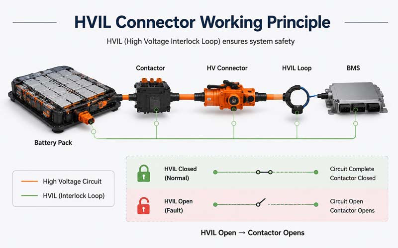
HVIL circuits continuously monitor whether high-voltage connectors, service disconnects, and enclosures are properly engaged. If the loop is interrupted, the control system immediately disables the high-voltage contactors.
Although the HVIL circuit carries only a low-voltage signal, its reliability is essential to the safe operation of the entire system.
This article explains how HVIL connectors work, common failure modes, and the validation tests used to ensure robust performance.
What Is HVIL?
HVIL stands for High Voltage Interlock Loop.
It is a low-current monitoring circuit that passes through:
- battery pack connectors
- inverter connectors
- onboard chargers
- DC fast charging interfaces
- service disconnects
- high-voltage enclosures
When all connectors are fully mated and covers are closed, the loop remains intact.
If any component is opened or partially disconnected, the loop opens and the system shuts down high voltage.
Why HVIL Is Important
HVIL helps protect:
- service technicians
- assembly operators
- end users
- vehicle electronics
Typical safety functions include:
- disabling contactors before connector separation
- detecting incomplete mating
- monitoring service access covers
- preventing energized exposure
In most EV architectures, HVIL is part of the functional safety strategy.
Basic HVIL Operating Principle
The battery management system (BMS) or vehicle control unit injects a low-voltage signal through the interlock loop.
The controller monitors:
- loop continuity
- resistance value
- voltage level
If the signal falls outside expected limits, a fault is triggered.
Some systems use simple open/closed detection, while others use resistor coding to identify specific components.
HVIL Connector Design Features
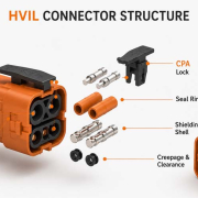
A dedicated HVIL connector typically includes:
- two low-voltage interlock contacts
- staggered contact lengths
- early-break / late-make sequencing
- CPA locking features
- sealed housing
- mechanical polarization
The HVIL contacts are usually designed to disconnect before the high-voltage power contacts separate.
Early-Break / Late-Make Concept
HVIL contacts are intentionally longer or shorter than power contacts.
During Unmating
The HVIL circuit opens first, allowing contactors to open before high-voltage contacts separate.
During Mating
Power contacts are fully engaged before the HVIL loop closes.
This sequencing is critical to system safety.
Common HVIL Failure Modes
1.Contact Fretting
Micro-motion can increase resistance and cause intermittent loop faults.
2.Incomplete Mating
If the connector is not fully seated, HVIL continuity may be unstable.
3.Terminal Back-Out
Improper terminal retention can interrupt the circuit.
4.Corrosion or Water Ingress
Moisture may increase resistance or cause open circuits.
5.Broken HVIL Wires
Small-gauge wires are vulnerable to fatigue and handling damage.
6.Contaminated Contacts
Debris or oxidation can degrade signal integrity.
Design Considerations for Reliable HVIL Performance
Key design priorities include:
- stable low-current contact resistance
- robust terminal retention
- vibration-resistant locking
- environmental sealing
- clear mating confirmation
- protected wire routing
Because HVIL circuits carry very low current, they are especially sensitive to contamination and fretting.
Validation Test Points
Typical validation activities include:
- contact resistance measurement
- mating and unmating force
- terminal retention force
- vibration testing
- thermal cycling
- humidity exposure
- salt spray
- sealing tests
- mechanical shock
Functional monitoring should verify that the HVIL circuit opens and closes in the correct sequence.
Critical Functional Checks
During validation, engineers should confirm:
- HVIL opens before power contacts disengage
- HVIL closes only after full mating
- resistance remains within specification
- no intermittent opens occur during vibration
- CPA and locking systems function correctly
Standards and Specifications
Relevant standards may include:
- LV214
- USCAR-2
- OEM high-voltage connector specifications
- ISO 6469
- ISO 26262
Requirements vary by customer and application.
Typical Applications
HVIL connectors are widely used in:
- EV battery packs
- inverters
- PDU (Power Distribution Units)
- onboard chargers
- DC fast charge systems
- ESS battery cabinets
How FPIC Supports HVIL Connector Projects
FPIC provides custom high-voltage connector and cable assembly solutions with:
- integrated HVIL circuits
- sealed connector designs
- CPA and TPA features
- continuity, IR, and HiPot testing
- application engineering support
We help customers develop reliable high-voltage interconnect systems for EV and energy applications.
Final Thoughts
HVIL connectors carry only a low-voltage signal, but they play a critical role in high-voltage safety.
- A robust design requires:
- correct contact sequencing
- stable low-current performance
- secure mechanical locking
- environmental protection
- thorough validation
In EV systems, the reliability of the HVIL circuit is essential to protecting both people and equipment.
FAQ
What does HVIL stand for?
High Voltage Interlock Loop.
What happens when the HVIL circuit opens?
The system commands the high-voltage contactors to open and disables high voltage.
Why are HVIL contacts sequenced differently from power contacts?
To ensure the safety circuit opens before high-voltage contacts separate.
Can corrosion cause HVIL faults?
Yes. Low-current circuits are highly sensitive to contamination and corrosion.
Is HVIL required in EV systems?
It is widely used as a core safety mechanism in high-voltage architectures.
Developing High-Voltage Connectors with HVIL?
FPIC provides custom high-voltage connectors and cable assemblies with integrated HVIL solutions for EV, ESS, and industrial applications.
Contact us to discuss your design and validation requirements.
Resources
- ISO 6469 – Electrically Propelled Road Vehicles Safety Specifications
Safety requirements for EV high-voltage systems. - LV214 – Environmental and Electrical Requirements for Automotive Connectors
Automotive connector validation standard widely used by OEMs. - USCAR-2 – Performance Specification for Automotive Connectors
Defines connector reliability and environmental tests. - ISO 26262 – Functional Safety for Road Vehicles
Functional safety framework for automotive systems. - TE Connectivity – HVIL Design Concepts
Technical guidance on high-voltage interlock connector design.