How Vibration Affects Automotive Connector Reliability
An automotive connector can pass continuity, contact resistance, insulation, and mating checks during initial inspection and still develop an electrical failure after months or years of vehicle operation.
The reason is that initial testing evaluates the connection at a specific moment. Vehicle vibration, thermal expansion, harness movement, and repeated mechanical stress can gradually change the contact interface, terminal position, locking condition, and surrounding connection system.
Quick Answer:
An automotive connector can pass initial electrical testing but fail after long-term vibration because microscopic movement at the contact interface can cause plating wear, fretting corrosion, and higher contact resistance. Vibration can also affect terminal retention, connector locking, solder joints, and wire-harness strain, eventually causing intermittent or permanent electrical failure.
The key engineering question is therefore not simply:
“Does the connector work now?”
It is:
“Will the electrical interface remain stable after long-term mechanical and environmental stress?”
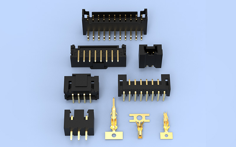
Why Vibration Creates Long-Term Connector Failures
Automotive connectors operate in an environment that is very different from a stationary bench test.
Depending on their location in the vehicle, they may experience combinations of:
- road-induced vibration;
- drivetrain and motor vibration;
- mechanical shock;
- temperature cycling;
- cable and harness movement;
- assembly preload;
- moisture and contamination;
- repeated thermal expansion and contraction.
TE Connectivity describes connectors for demanding applications as needing to withstand mechanical stresses that include heavy vibration, while secure locking and positive contact retention are important characteristics for harsh-environment connections.
The critical issue is often not large visible movement of the complete connector.
Instead, very small relative movements may occur between the mating contact surfaces.
These movements can gradually change an interface that initially showed excellent electrical performance.
A simplified failure path is:
Vehicle Vibration → Contact Micro-Movement → Surface Wear → Fretting Corrosion → Contact Resistance Growth → Intermittent or Permanent Failure
Other mechanical paths may occur at the same time:
Vibration → Terminal Movement → Retention Loss
and:
Harness Movement → Connector Load → Housing and Locking Stress
This is why automotive connector vibration reliability must be evaluated as a system rather than as a single material property.
How Contact Micro-Movement Leads to Fretting Corrosion
When male and female terminals mate, electrical current does not necessarily flow uniformly through the entire visible contact surface.
At microscopic scale, current passes through multiple contact points created by the pressure between the mating surfaces.
If vibration or thermal expansion causes repeated small relative movements, the contact surfaces may begin to wear.
This process can:
- disturb or remove part of the surface plating;
- generate metallic wear debris;
- expose material that can oxidize;
- reduce the quality of the effective conductive interface;
- increase contact resistance.
TE identifies fretting corrosion as a traditional failure mechanism in tin-plated connections and explains that relative movement caused by vibration and thermal expansion can occur between male and female contacts. Its Micro-MaTch design uses an additional positioning spring specifically to absorb this movement.
The important point is that the connector may still appear mechanically intact.
There may be:
- no broken housing;
- no visibly bent terminal;
- no disconnected plug.
Yet electrical resistance at the microscopic contact interface may already be changing.
That is why long-term connector reliability cannot be judged only through visual inspection.
Why Increasing Contact Resistance Matters
A gradual increase in contact resistance can create several consequences.
Voltage Drop
More resistance at the interface increases voltage drop across the connection.
For low-voltage automotive circuits, even relatively small changes may affect sensitive electronics, sensors, control modules, or signal references.
Local Heating
Electrical resistance also creates heat when current flows.
This links vibration reliability directly to thermal reliability.
Vibration itself does not necessarily create significant electrical heat. The thermal risk develops when vibration changes the contact condition and causes resistance to rise.
In higher-current circuits, this can become increasingly important because resistive power loss grows rapidly as current increases.
Intermittent Electrical Signals
Micro-movement can also create temporary changes in contact continuity.
A connector may therefore show:
- intermittent signal loss;
- sporadic control faults;
- communication errors;
- unstable sensor readings.
These failures can be difficult to diagnose because the connection may work normally when the vehicle is stationary or when the connector is inspected in the workshop.
IEC 60512-2-3 defines a method for determining contact resistance variation under specified dynamic conditions, while IEC 60512-2-5 addresses detection of contact disturbance under dynamic conditions.
This illustrates an important difference between measuring static contact resistance and verifying whether that resistance remains stable during mechanical stress.
Contact Force Must Remain Stable Under Vibration
Contact normal force is one of the key variables that controls the electrical interface.
The female terminal normally incorporates a spring structure that presses against the mating male contact.
That force must be sufficient to maintain a stable conductive interface.
If contact pressure is too low, the system may become more sensitive to:
- vibration;
- surface contamination;
- oxidation;
- fretting;
- resistance variation.
However, simply maximizing contact force is not the solution.
Excessive contact load can create other problems, including:
- higher mating force;
- accelerated plating wear;
- greater terminal stress;
- housing deformation;
- reduced mating-cycle life.
Molex notes that insufficient pressure increases contact resistance and vulnerability to fretting corrosion and signal dropouts under vibration, while excessive contact load may accelerate plating wear or overstress connector components.
The engineering target is therefore:
Stable Contact Force + Controlled Mating Force + Long-Term Electrical Reliability
This is particularly important in multi-contact automotive connectors where the operating force of many individual terminals combines into the total connector mating force.
Mating Force and Contact Force Are Not the Same
These terms are sometimes treated as interchangeable, but they describe different aspects of connector performance.
Contact normal force is the mechanical pressure acting at the electrical contact interface.
Connector mating force is the total force required to engage the complete connector.
Total mating force can include contributions from:
- terminal spring force;
- contact friction;
- seals;
- housing alignment;
- locking structures;
- multiple simultaneously engaging terminals.
A connector may therefore be optimized for lower operating effort while still maintaining sufficient contact pressure.
The objective is not simply to make a connector “tight.”
The objective is to create a predictable mechanical interface that maintains stable electrical contact over the intended service life.
Terminal Retention Is a Separate Reliability Requirement
Contact force controls the interface between mating conductive surfaces.
Terminal retention performs a different job.
It keeps the terminal correctly positioned inside the connector housing.
This distinction is important because an electrically good contact cannot remain reliable if the terminal begins to move backward inside the housing.
Under vibration or wire-harness load, insufficient retention may result in:
- terminal back-out;
- reduced mating depth;
- partial contact engagement;
- intermittent continuity;
- complete circuit interruption.
Molex describes contact retention as the mechanical means used to keep connector elements secured so electrical continuity can be maintained under stresses such as vibration and thermal cycling.
| Design Factor | Primary Function |
| Contact normal force | Maintains the conductive contact interface |
| Terminal retention | Keeps the terminal correctly seated in the housing |
| Connector locking | Keeps plug and receptacle fully mated |
A robust automotive connector must control all three.
How TPA and CPA Improve Connector Security
Automotive connectors frequently use additional locking or assurance structures.
A primary terminal lock normally retains the contact inside the housing, while secondary systems can provide additional security.
Two terms commonly used in automotive connector design are:
TPA — Terminal Position Assurance
TPA helps verify and secure the correct position of terminals inside the connector housing.
Its purpose is to reduce the risk of a terminal being incompletely inserted or moving out of its intended position.
CPA — Connector Position Assurance
CPA helps confirm and secure the mated condition of the connector itself.
Its purpose is different from terminal retention: it acts at the plug-to-receptacle connection level.
FPIC’s automotive connector technical materials distinguish CPA as a connector-position assurance structure and TPA as a terminal-position assurance structure.
These secondary structures are particularly valuable where vibration, harness loads, difficult assembly access, or safety requirements make incomplete engagement unacceptable.
Housing and Locking Design Matter Under Vibration
An automotive connector housing is not simply a plastic shell.
It performs several mechanical functions simultaneously:
- terminal positioning;
- mating guidance;
- polarization;
- retention;
- connector locking;
- protection against mismating;
- environmental sealing where required.
A well-designed terminal cannot provide reliable service if the housing allows excessive relative movement or the connector lock disengages under vibration.
For harsh environments, TE highlights secure locking and positive contact-retention systems as important characteristics of rugged connectors.
Engineers should therefore evaluate:
- primary latch geometry;
- secondary locking;
- CPA design where required;
- housing stiffness;
- material creep and stress relaxation;
- connector-to-device mounting;
- seal compression;
- tolerance accumulation;
- mating alignment.
The complete locking architecture must remain stable throughout the expected mechanical and environmental lifecycle.
Harness Strain Can Amplify Connector Stress
The connector does not operate independently from the wire harness.
This is especially important in automotive applications.
A wire harness can introduce mechanical forces through:
- cable weight;
- routing tension;
- tight bending;
- engine or vehicle movement;
- incorrect clip spacing;
- assembly preload;
- unsupported cable length;
- vibration transmitted along the conductors.
If the harness is not properly supported, these forces can reach the rear of the connector and eventually affect the terminals.
A simplified mechanical path is:
Harness Movement → Cable Load → Terminal Stress → Contact Micro-Movement
For this reason, automotive connection reliability should consider the complete relationship between:
- connector;
- terminal;
- conductor;
- seal;
- strain relief;
- harness clips;
- cable exit direction;
- equipment mounting.
Cable Exit Direction
A harness that leaves the connector at an unsuitable angle can continuously load the terminal or housing.
Bend Radius
Forcing the cable into a very tight bend near the connector can introduce long-term mechanical stress.
Harness Fixing Points
Correctly positioned clips or supports reduce the amount of cable movement transferred to the connector.
Conductor Size
Larger conductors have greater stiffness and can transmit more mechanical force to the connection.
This is one reason why connector and wire-harness engineering should be considered together rather than purchased as completely independent components.
PCB Headers Have Additional Vibration Risks
Automotive PCB connectors require another level of analysis.
For a wire-to-wire connector, engineers primarily consider:
Harness → Terminal → Contact → Housing → Connector Lock
A PCB header adds another chain:
Receptacle → Header Contact → PCB Pin → Solder Joint → PCB
This introduces additional potential vibration interfaces.
Pin Position and Alignment
Poor pin positioning can create mechanical preload during mating or soldering.
Solder-Joint Stress
Vibration transmitted through the connector body can eventually reach the solder joints.
PCB Movement
The printed circuit board itself can flex under vibration.
Housing Retention
The header housing must remain mechanically stable relative to the PCB.
Harness Leverage
A harness attached to the mating receptacle may create bending or leverage forces on the header.
This is particularly important in control modules, lighting systems, power-seat electronics, window-control modules, multimedia systems, and other vehicle electronics.
For an automotive PCB connector, vibration reliability is a system property rather than a terminal-only property.
FPIC’s internal automotive connector materials define header connectors as structures containing fixed male contacts that normally connect to the PCB or directly to internal equipment circuits.
This is why PCB-header validation should consider both contact reliability and board-level mechanical integrity.
Terminal Material Influences Vibration Performance
Automotive terminal material selection requires a balance between electrical and mechanical properties.
Important characteristics include:
- electrical conductivity;
- spring strength;
- yield behavior;
- fatigue resistance;
- formability;
- stress-relaxation resistance;
- corrosion behavior.
Typical connector contact materials include different copper alloys selected according to application requirements.
A highly conductive material alone may not be sufficient if it cannot maintain the required spring behavior after repeated mechanical and thermal stress.
Conversely, a highly elastic material may introduce unnecessary electrical resistance or cost if used without considering current and signal requirements.
The terminal geometry, material, heat treatment, contact pressure, and plating system should therefore be developed together.
Plating Selection Affects Fretting Resistance
Contact plating influences:
- resistance;
- wear;
- oxidation;
- corrosion;
- friction;
- mating durability.
Gold and tin are widely used in connector systems, but they behave differently.
Molex recommends carefully matching contact finishes and notes that tin-to-tin systems require validation for fretting corrosion, oxidation, and related long-term effects, while mismatched gold-to-tin interfaces can introduce additional reliability risk.
This does not mean that one plating material is universally better.
The appropriate system depends on:
- signal or power level;
- contact force;
- environment;
- mating-cycle requirement;
- temperature;
- vibration;
- cost;
- customer specification.
The important principle is:
Plating should be selected as part of the contact system, not as an isolated specification.
Why Initial Electrical Testing Is Not Enough
Initial testing is essential.
But it answers only part of the reliability question.
Initial tests can verify:
- continuity;
- contact resistance;
- insulation resistance;
- withstand voltage;
- pin position;
- dimensional conformity.
These measurements answer:
“Does the connector meet requirements now?”
Reliability testing asks a different question:
“Will the connector still meet those requirements after mechanical and environmental stress?”
That distinction is fundamental.
A connector may initially have:
- correct contact force;
- low resistance;
- proper terminal seating;
- correct housing lock.
Long-term vibration can gradually change one or more of these conditions.
Therefore, a robust validation program should compare electrical and mechanical performance before and after stress, and in some cases monitor electrical continuity while the stress is being applied.
How Vibration Testing Should Be Evaluated
A vibration test should not be treated simply as:
Run the machine for a specified number of hours and check whether the connector broke.
A useful validation plan defines what must be measured before, during, and after the test.
Before Vibration Testing
Typical checks may include:
- visual inspection;
- terminal position;
- locking condition;
- contact resistance;
- continuity;
- mating condition;
- dimensional checks where necessary.
During Vibration Testing
Depending on the specification, the test may monitor:
- transient discontinuity;
- contact disturbance;
- resistance variation;
- connector movement.
IEC 60512-6-5 defines a method intended to assess the ability of components to withstand specified levels of random vibration.
IEC 60512-2-3 covers contact-resistance variation under dynamic conditions, while IEC 60512-2-5 addresses contact disturbance.
The exact test severity, mounting arrangement, frequency range, acceleration, duration, monitoring requirements, and acceptance limits must follow the applicable product specification or customer requirement.
After Vibration Testing
The connector should be evaluated again for possible changes such as:
- increased contact resistance;
- terminal back-out;
- housing damage;
- lock deterioration;
- contact wear;
- seal displacement;
- wire or crimp damage;
- solder-joint damage in PCB applications.
The engineering value comes from comparing the connector condition before and after exposure.
Vibration and Thermal Cycling Should Be Considered Together
Vehicles do not experience vibration in isolation.
Temperature also changes during operation.
Different materials expand and contract at different rates, including:
- copper-alloy terminals;
- plastic housings;
- PCB laminates;
- seals;
- wire insulation;
- connector plating.
Repeated temperature changes can therefore create additional relative movement between contact surfaces.
TE specifically identifies vibration and thermal expansion as sources of relative contact movement associated with fretting-corrosion risk.
This interaction explains why a connector that performs acceptably in a short room-temperature mechanical test may require broader environmental validation for automotive use.
Depending on the application, a reliability plan may therefore combine:
- vibration;
- thermal cycling;
- thermal shock;
- humidity;
- salt spray;
- electrical measurements.
Crimp Quality Also Influences Vibration Reliability
For wire-to-connector applications, the crimp is another critical mechanical and electrical interface.
A properly controlled crimp should provide a stable connection between the conductor and terminal.
Important controls can include:
- conductor crimp height;
- crimp width;
- conductor position;
- insulation support;
- bellmouth condition;
- strand integrity;
- pull force;
- crimp cross-section.
An excessively loose crimp may allow conductor movement.
An excessively tight crimp can damage strands or weaken the conductor.
Either condition may reduce the connection’s ability to tolerate vibration.
FPIC’s internal crimping standards include controls for conductor crimp height, insulation crimping, conductor position, pull-force testing, and cross-section analysis.
This reinforces an important reliability principle:
The terminal contact and the wire termination must both remain mechanically stable.
A Practical Automotive Connector Reliability Checklist
Before selecting or developing an automotive connector, engineers should define the complete operating environment.
| Design Area | Questions to Confirm |
| Electrical circuit | Signal, low-current power, or higher-current circuit? |
| Contact system | What normal force and contact geometry are required? |
| Terminal material | Does it balance conductivity and spring performance? |
| Plating | Is it suitable for vibration, wear, environment, and lifecycle? |
| Terminal retention | How is terminal back-out prevented? |
| Connector locking | Is primary or secondary locking required? |
| PCB interface | Is it wire-to-wire, wire-to-board, or PCB header? |
| Harness | What conductor size, cable weight, and exit direction apply? |
| Strain relief | How is harness movement isolated from the terminals? |
| Environment | What vibration, temperature, moisture, and contamination occur? |
| Testing | What electrical measurements are required before and after vibration? |
| Production | How are terminal position, crimping, assembly, and traceability controlled? |
A complete specification helps prevent the common mistake of evaluating vibration resistance as a single connector feature.
How FPIC Supports Automotive Connector Reliability
FPIC supports customized automotive low-voltage connectors, automotive PCB headers and receptacles, terminals, stamped components, and related cable assemblies.
Our automotive connector development and manufacturing capabilities cover multiple stages of the connection system.
Contact and Terminal Development
FPIC supports terminal structure, material, plating, retention, and manufacturing evaluation according to the application requirements.
Housing and Locking Development
Connector housing, keying, terminal retention, mating alignment, and locking structures can be evaluated during custom product development.
Automotive PCB Headers
FPIC develops customized board-side automotive connector solutions for vehicle electronic modules, including applications such as lighting control, power seats, window-lift systems, multimedia, and related control electronics.
Wire Harness Integration
Where the project requires a complete connection assembly, connector, terminal, conductor, crimping, strain relief, and harness routing requirements can be evaluated together.
In-House Manufacturing Processes
FPIC’s manufacturing platform includes:
- precision stamping;
- plastic injection molding;
- insert molding;
- tooling development;
- automated connector assembly;
- wire processing;
- cable assembly;
- CCD-supported inspection.
Reliability Testing
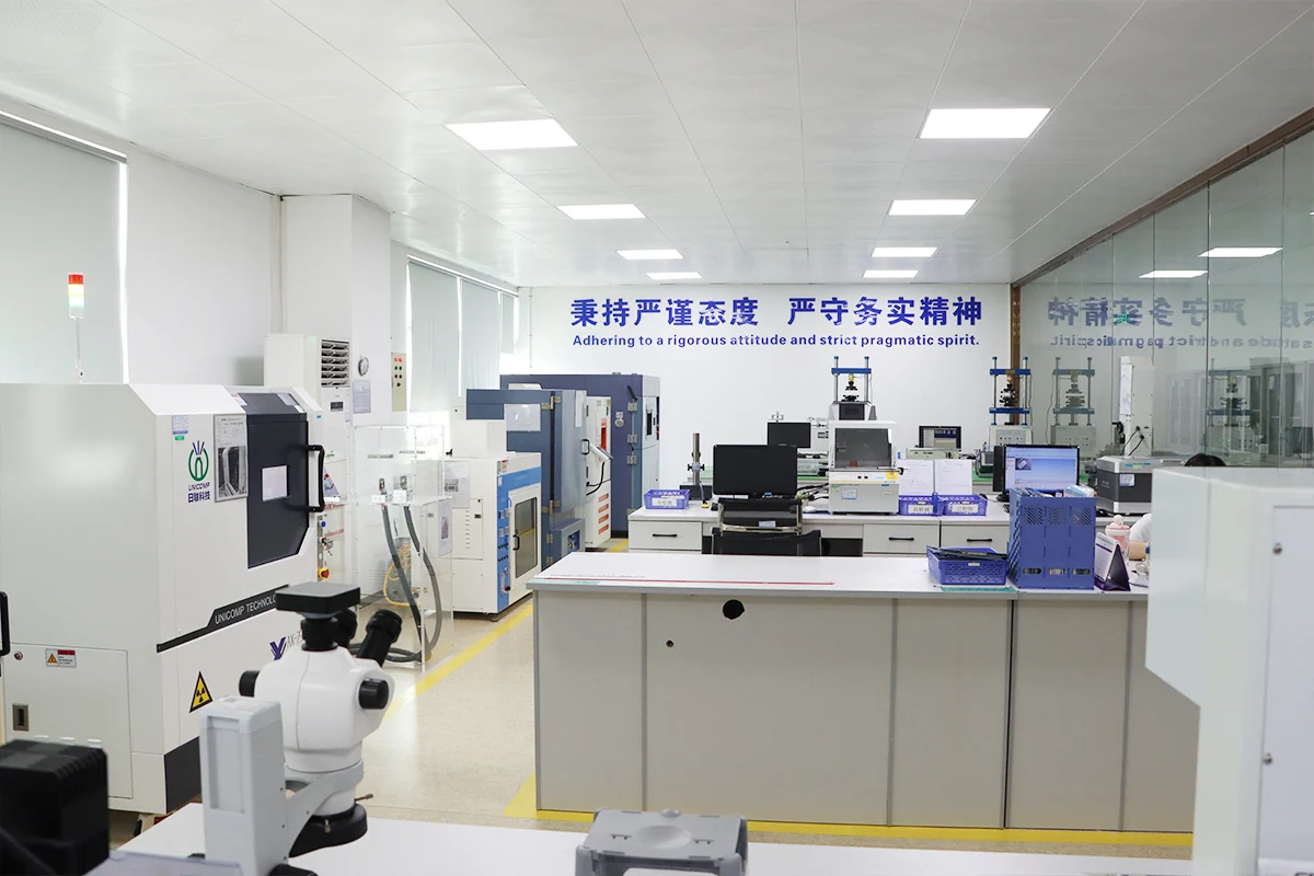
FPIC’s internal laboratory capability includes equipment for:
- contact impedance testing;
- insertion and extraction force testing;
- temperature-rise testing;
- vibration testing;
- thermal shock;
- withstand voltage;
- insulation testing;
- dimensional measurement;
- X-ray inspection.
FPIC’s technical materials also identify automotive connector validation areas including contact resistance, temperature rise, mating force, terminal retention, vibration, high- and low-temperature exposure, temperature/humidity cycling, solder-heat resistance, and salt spray.
Company capability materials list vibration equipment, contact-impedance testers, temperature-rise testers, insertion/extraction-force equipment, thermal-shock chambers, X-ray systems, and dimensional inspection equipment.
For automotive projects, FPIC operates under IATF 16949 and supports product-development and manufacturing controls appropriate to customized automotive connector programs.
The objective is not merely to manufacture a connector that passes an initial continuity check.
It is to establish a controlled development and production process that supports stable connection performance through the intended operating environment.
Frequently Asked Questions
1. Why can an automotive connector pass continuity testing but fail under vibration?
Initial continuity testing confirms that the electrical path is complete at the time of measurement. Long-term vibration can create microscopic contact movement, plating wear, fretting corrosion, terminal movement, or locking stress that gradually changes the connection and may eventually cause intermittent or permanent failure.
2. What is fretting corrosion in an automotive connector?
Fretting corrosion is degradation that occurs when loaded mating surfaces experience very small repeated relative movements. In electrical contacts, this movement can disturb plating, generate wear debris and oxidation products, and increase contact resistance.
3. How does vibration increase connector contact resistance?
Vibration can create repeated micro-movement at the contact interface. Over time, this may wear the contact surface, change the effective conductive contact area, and promote oxidation or fretting debris, causing resistance to increase.
4. What prevents an automotive terminal from backing out?
Terminal retention normally depends on the primary terminal-locking structure, correct terminal insertion, and, in many automotive systems, a secondary Terminal Position Assurance (TPA) feature.
5. What is the difference between TPA and CPA?
TPA helps secure and verify terminal position inside the connector housing. CPA helps secure and verify the fully mated position of the plug and receptacle.
6. Does higher contact force always improve vibration reliability?
No. Insufficient force can increase resistance and micro-movement risk, but excessive contact force may increase mating effort, wear, and spring stress. The contact system should be optimized for stable force throughout the required service life.
7. Why does the wire harness affect connector vibration reliability?
The harness can transfer cable weight, bending force, and vibration into the connector. Improper routing, insufficient strain relief, or unsuitable fixing points can increase load on the terminal and contact interface.
8. Are automotive PCB headers affected by vibration differently from wire-to-wire connectors?
Yes. PCB headers introduce additional interfaces such as header pins, solder joints, PCB movement, and board mounting. Their vibration reliability must therefore be evaluated at both the contact and PCB levels.
Conclusion
Automotive connector reliability cannot be judged only by whether a new connector passes an initial electrical test.
Long-term vibration can affect several parts of the connection system:
Contact Interface → Terminal Retention → Housing Locking → PCB Interface → Wire Harness
Microscopic contact movement can lead to fretting corrosion and resistance growth. Terminal movement can reduce mating depth. Harness strain can transfer mechanical loads into the connector. PCB headers introduce additional solder-joint and board-level stresses.
For this reason, reliable automotive connection design requires electrical, mechanical, material, harness, and validation requirements to be considered together.
FPIC supports automotive connector projects from terminal and housing development through PCB-header design, cable integration, tooling, manufacturing, testing, and repeat production.
Discuss Your Automotive Connector Project
Developing a customized automotive connector, PCB header, terminal, or related cable assembly?
Send FPIC your 2D or 3D drawings, electrical requirements, mating interface, wire specification, operating environment, validation requirements, and forecast demand for engineering evaluation.
Email: info@fpiconn.com
Resources
- TE Connectivity — Micro-MaTch Miniature Ribbon Cable Connectors and Fretting Corrosion Resistance.
- TE Connectivity — Rugged Connectors for Harsh Conditions.
- Molex — Engineering Contact Engagement and Normal Force for Connector Performance.
- Molex — Connector Contact Retention Guide.
- Molex — Gold or Tin vs. Gold and Tin Contact Finishes.
- IEC 60512-2-1 — Contact Resistance — Millivolt Level Method.
- IEC 60512-2-3 — Contact Resistance Variation Under Dynamic Conditions.
- IEC 60512-2-5 — Contact Disturbance Under Dynamic Conditions.
- IEC 60512-6-5 — Random Vibration Test Method.