Tag Archive for: Automotive Connector Design

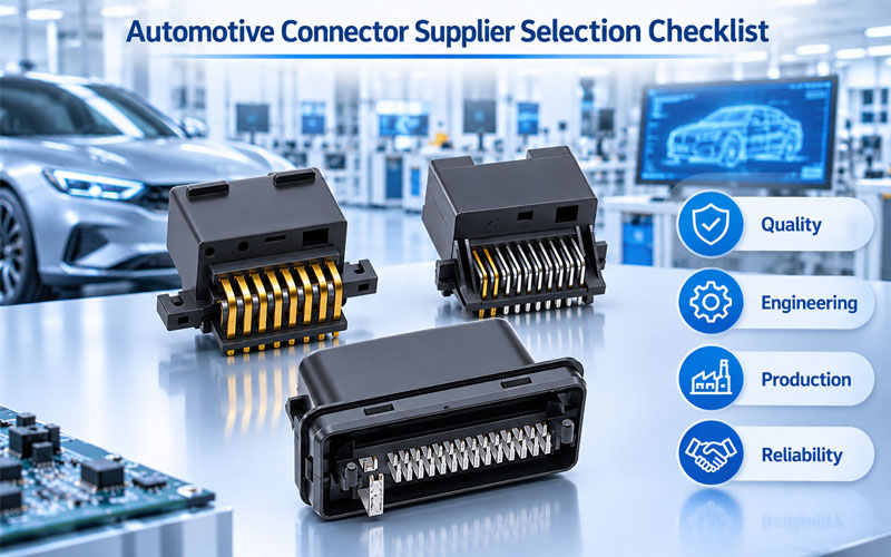
Automotive Connector Supplier Selection Checklist

Choosing an automotive connector supplier involves much more than comparing quotations, product specifications, or delivery lead times. A connector may be a relatively small component, but its performance can directly affect electrical continuity, vehicle safety, system reliability, and manufacturing efficiency.

For OEMs and Tier 1 suppliers, selecting the right manufacturing partner requires a structured evaluation of technical competence, quality management, engineering support, production capability, and long-term supply chain stability.

A supplier that can provide samples quickly may not necessarily be ready for mass production. Similarly, a competitive quotation does not guarantee consistent product quality or effective engineering support throughout the project lifecycle.

This guide provides a practical automotive connector supplier selection checklist for OEM projects, covering the key factors to evaluate before approving a supplier.
Automotive Connector Supplier Selection Checklist


1.Confirm Automotive Quality Management System Requirements

A supplier’s quality management system is one of the first areas to review.

Automotive projects typically require more structured quality controls than general industrial applications. OEMs should confirm whether a potential supplier has an established quality management system and whether its certification status meets the specific project requirements.

What to check

  • Does the manufacturing site hold a valid IATF 16949 certification, where required?
  • Is the certificate issued by an accredited certification body?
  • Does the certification scope cover the relevant manufacturing activities?
  • Is the actual production site the same site identified in the certificate?
  • Are internal audits and management reviews conducted regularly?
  • Are nonconformities managed through documented corrective-action procedures?
  • Can the supplier demonstrate continuous improvement in manufacturing quality?

IATF 16949 is an automotive-specific quality management system standard that works alongside ISO 9001 and addresses requirements for automotive production and service parts. However, certification alone should not be treated as proof that a supplier meets every OEM requirement. <Cite refs={[“turn257028search6″,”turn257028search9”]}/>

OEMs should also review applicable customer-specific requirements. These may define additional expectations for supplier approval, process audits, documentation, and product validation. The IATF publishes customer-specific requirement documents for participating automotive manufacturers. <Cite refs={[“turn257028search1”]}/>

Practical recommendation: Request the current certificate, verify its validity and scope, and confirm the quality requirements applicable to the specific project and customer.


2.Evaluate Engineering and Customization Capabilities

Automotive connector projects often involve application-specific requirements rather than standard catalog products.

Connector dimensions, terminal geometry, contact materials, plating, locking structures, sealing performance, and electrical characteristics may all need to be adjusted to match the vehicle’s electrical architecture.

A capable supplier should be able to participate in engineering discussions before the design is finalized.

What to check

  • Can the supplier support customized connector development?
  • Does it have experience with terminal and housing design?
  • Can engineers review drawings and technical specifications?
  • Can the supplier evaluate material and plating options?
  • Does it understand contact force, terminal retention, and mating interface requirements?
  • Can it assess sealing structures and environmental protection requirements?
  • Can it identify potential manufacturing or assembly risks during design review?
  • Is engineering support available throughout prototype and production stages?

Important engineering capabilities

Evaluation area What OEMs should verify
Connector housing Material selection, dimensional accuracy, structural design
Terminal system Contact geometry, retention, mating performance
Contact plating Material suitability, thickness control, corrosion considerations
Sealing design Seal structure, water and dust protection
Electrical performance Current rating, voltage rating, contact resistance
Mechanical performance Mating cycles, insertion force, vibration resistance

A supplier should not simply confirm that a design is manufacturable. It should also help identify potential risks associated with the intended operating environment.

For example, a connector used near an engine compartment may require different temperature and vibration considerations from one installed inside a protected electronic control unit.


3.Review Prototype Development and Validation Capabilities

Prototype development is an important stage for identifying design and manufacturing issues before mass production.

OEMs should evaluate whether a supplier can support both sample manufacturing and the engineering verification activities required by the project.

What to check

  • Can the supplier produce prototypes according to the latest approved drawings?
  • Are prototype materials and manufacturing processes representative of the intended production design?
  • Can dimensional inspection reports be provided?
  • Are electrical tests available?
  • Can mechanical performance be evaluated?
  • Can environmental validation be arranged?
  • Does the supplier maintain sample revision and change records?
  • Can engineering issues be documented and resolved systematically?

Depending on the connector application, validation may include:

  • Contact resistance testing
  • Insulation resistance testing
  • Dielectric withstand testing
  • Temperature rise testing
  • Terminal retention testing
  • Insertion and withdrawal force testing
  • Vibration and mechanical shock testing
  • Thermal cycling
  • Salt spray or corrosion testing
  • Water and dust ingress testing

Not every connector requires every test. The validation plan should be based on the product specification, installation environment, applicable standards, and OEM requirements.

Practical recommendation: Ask for a sample development plan that identifies the prototype schedule, inspection requirements, validation methods, responsible personnel, and issue-resolution process.


4.Assess Manufacturing Process Control and Production Equipment

A supplier may produce acceptable prototypes but encounter quality variation when production volumes increase.

For OEM projects, manufacturing capability must be evaluated at the process level—not just by looking at the finished connector.

Relevant manufacturing processes may include:

  • Precision metal stamping
  • Terminal forming
  • Injection molding
  • Contact plating
  • Terminal assembly
  • Connector housing assembly
  • Crimping and cable integration, where applicable
  • Electrical and dimensional inspection

What to check

  • Are critical manufacturing processes documented?
  • Does the supplier use defined process parameters?
  • Are production machines maintained and calibrated?
  • Are critical dimensions monitored during production?
  • Are automated inspection systems used where appropriate?
  • Are operators trained for their assigned processes?
  • Are process changes reviewed and approved?
  • Are production defects recorded and analyzed?

Look beyond equipment quantity

The presence of automated machines does not automatically guarantee manufacturing consistency.

OEMs should understand how equipment is controlled, how inspection data is used, and how abnormal conditions are handled.

For example, terminal assembly may require monitoring of insertion position, terminal deformation, locking engagement, and other critical characteristics. A mature production process should define how these characteristics are checked and what happens when results fall outside approved limits.


5.Verify Quality Inspection and Testing Systems

A reliable automotive connector supplier should have an inspection system that covers incoming materials, in-process production, and finished products.

Quality should be built into the manufacturing process rather than depending only on final inspection.

What to check

Quality control stage Key evaluation points
Incoming inspection Raw material, terminal material, plating and component verification
In-process inspection Critical dimensions, assembly position, process parameters
Final inspection Appearance, dimensions, assembly completeness
Electrical testing Continuity, resistance, insulation or dielectric tests as specified
Functional inspection Locking, mating, retention and other product-specific checks
Nonconformance control Defect identification, segregation, investigation and corrective action

OEMs should also ask how inspection equipment is calibrated and how measurement results are recorded.

For critical characteristics, the supplier should be able to explain the inspection method, acceptance criteria, sampling frequency, and reaction plan.

A documented control plan is particularly important because it connects product and process risks with actual manufacturing controls. AIAG’s Control Plan 1st Edition provides guidance on control plan development and includes the concept of Safe Launch controls for early production stages. <Cite refs={[“turn257028search8″,”turn257028search7”]}/>


6.Check Traceability and Documentation Management

Traceability becomes especially important when a quality issue occurs after products have been delivered to an OEM or Tier 1 customer.

Without sufficient production records, it may be difficult to identify affected batches, determine the root cause, or establish the scope of containment.

What to check

  • Can finished products be traced to production batches?
  • Are raw materials and key components recorded?
  • Are production dates, machine information, and inspection results retained?
  • Are product revisions and engineering changes documented?
  • Can the supplier identify affected shipments during a quality investigation?
  • Are quality records stored and retrieved systematically?
  • Does the supplier have a defined document-control process?

For customized connectors, revision management is particularly important.

A change in terminal geometry, plating specification, housing material, or sealing structure may affect product performance. OEMs should confirm that obsolete drawings and specifications cannot be used accidentally in production.


7.Evaluate Mass Production Capacity and Delivery Reliability

A supplier’s ability to manufacture samples does not necessarily demonstrate its ability to support long-term OEM demand.

Before supplier approval, OEMs should evaluate production capacity against forecast volumes, ramp-up requirements, and possible demand fluctuations.

What to check

  • What is the supplier’s current production capacity?
  • Is there sufficient capacity for the forecast project volume?
  • Can capacity be increased during a production ramp-up?
  • Are critical machines or processes potential bottlenecks?
  • Are backup machines or alternative production arrangements available?
  • How are production schedules managed?
  • What is the supplier’s historical on-time delivery performance?
  • How are urgent orders and demand changes handled?

Evaluate production readiness

A useful supplier review should include a capacity discussion covering:

  • Forecast demand and expected annual volume.
  • Available production capacity.
  • Equipment utilization and bottleneck processes.
  • Labor and shift arrangements.
  • Material availability and replenishment lead times.
  • Ramp-up planning and contingency capacity.

OEMs should also understand whether the supplier depends heavily on a single production line, machine, or external processing partner.

Capacity commitments should be supported by realistic production data rather than general assurances.


8.Review Supply Chain Stability and Material Management

Automotive connector production depends on consistent access to raw materials and specialized components.

Copper alloys, engineering plastics, plating materials, seals, and other purchased components can affect both product performance and delivery continuity.

What to check

  • Are key raw material suppliers qualified?
  • Are alternative sources available for critical materials?
  • Does the supplier monitor material quality and consistency?
  • Are incoming materials traceable?
  • How are long-lead-time components managed?
  • Are inventory levels aligned with project demand?
  • Does the supplier have a business continuity plan?
  • Are sub-tier suppliers monitored and evaluated?

Sub-tier supplier management deserves particular attention when critical processes such as plating or specialized material production are outsourced.

OEMs should understand which processes are performed internally and which depend on external suppliers. They should also review how outsourced processes are qualified, monitored, and controlled.


9.Assess Engineering Communication and Project Management

Even technically capable suppliers can create project delays if communication is slow or responsibilities are unclear.

OEM projects often involve multiple departments, including purchasing, engineering, quality, manufacturing, and logistics. A supplier should be able to coordinate with these teams throughout the development process.

What to check

  • Is there a designated project contact?
  • Can the supplier provide engineering support during design review?
  • Are technical questions answered within agreed timeframes?
  • Are project milestones clearly defined?
  • Are development risks communicated early?
  • Are sample changes and drawing revisions documented?
  • Are quality issues escalated through a defined process?
  • Can the supplier support customer audits and technical meetings?

A good supplier should communicate potential problems before they affect the project schedule.

For example, if a terminal design requires a tooling adjustment or a specified material has a long procurement lead time, the supplier should raise the issue early and provide a realistic recovery plan.


10.Compare Total Cost, Not Just Unit Price

Price is an important part of supplier selection, but the lowest quotation does not always represent the lowest overall project cost.

OEMs should consider the total cost of ownership, including development, tooling, testing, quality management, logistics, and potential production risks.

Cost factors to review

Cost category Questions to ask
Unit price Is the quotation based on the correct specification and volume?
Tooling Are tooling costs, ownership, maintenance, and modification fees clear?
Development Are prototype and engineering costs included?
Validation Which tests are included, and which require additional charges?
Logistics What are the packaging, freight, and delivery costs?
Quality How are sorting, rework, replacement, and warranty costs handled?
Engineering changes How are design and process changes quoted?

A transparent quotation should clearly define the scope of supply, assumptions, exclusions, and commercial conditions.

OEMs should compare suppliers using the same technical requirements and commercial assumptions to avoid misleading price comparisons.


11.Evaluate Long-Term Partnership and Continuous Improvement

Automotive projects often continue for several years, and supplier performance must remain consistent throughout the product lifecycle.

The selection process should therefore consider not only initial project readiness but also the supplier’s ability to support ongoing production.

What to check

  • Does the supplier monitor customer complaints and quality trends?
  • Are corrective actions verified for effectiveness?
  • Can it support engineering changes during production?
  • Does it review process performance regularly?
  • Are lessons learned incorporated into new projects?
  • Can it support spare parts or service requirements where applicable?
  • Does it have a structured approach to continuous improvement?

OEMs should also clarify responsibilities for engineering changes, product discontinuation, tooling maintenance, and end-of-life support before finalizing the supplier agreement.


12.Automotive Connector Supplier Selection Checklist

The following checklist can be used during supplier prequalification, technical evaluation, or on-site audits.

No. Evaluation category Key questions Priority
1 Quality certification Does the supplier meet the required automotive QMS requirements? High
2 Engineering capability Can it support custom connector design and engineering review? High
3 Prototype development Can it provide controlled samples and validation support? High
4 Manufacturing capability Are critical production processes stable and documented? High
5 Quality inspection Are incoming, in-process, and final inspections established? High
6 Traceability Can products and production records be traced by batch or lot? High
7 Production capacity Can the supplier meet forecast demand and ramp-up requirements? High
8 Supply chain Are critical materials and outsourced processes controlled? High
9 Project management Are communication, milestones, and escalation procedures clear? Medium
10 Commercial terms Are pricing, tooling, logistics, and change costs transparent? Medium
11 Risk management Are business continuity and contingency plans available? High
12 Continuous improvement Does the supplier monitor performance and implement corrective actions? Medium

Suggested Supplier Evaluation Scoring

OEMs can use a weighted scoring model to compare shortlisted suppliers objectively.

Evaluation category Suggested weight
Quality management 20%
Engineering and customization 20%
Manufacturing and process control 15%
Testing and validation 15%
Production capacity and delivery 10%
Supply chain and risk management 10%
Commercial competitiveness 5%
Communication and project support 5%
Total 100%

Score each category from 1 to 5:

  • 1 – Unsatisfactory: Major capability gaps or insufficient evidence.
  • 2 – Weak: Some capabilities exist, but significant improvements are required.
  • 3 – Acceptable: Meets the basic project requirements.
  • 4 – Strong: Demonstrates reliable processes and supporting evidence.
  • 5 – Excellent: Demonstrates mature capabilities and proven project performance.

The weighted score can help prioritize suppliers, but it should not replace mandatory approval requirements. A supplier that fails a critical safety, quality, compliance, or technical requirement should not be approved simply because its overall score is high.


13.Common Red Flags When Selecting an Automotive Connector Supplier

During supplier evaluation, OEMs should pay attention to warning signs that may indicate future project risks.

1.Certification without clear manufacturing scope

A supplier presents a certificate but cannot demonstrate that the actual production site and relevant processes are covered.

2.Limited engineering involvement

The supplier only accepts drawings and quotations but cannot provide meaningful technical feedback or identify manufacturing risks.

3.Unclear prototype-to-production transition

Samples are available, but there is no documented plan for tooling, process validation, production approval, or capacity verification.

4.Weak traceability

The supplier cannot identify production batches, material sources, or inspection records when asked.

5.Overpromised delivery capacity

The supplier commits to high volumes without providing capacity data, production planning, or material availability evidence.

6.Uncontrolled outsourced processes

Critical processes are outsourced, but supplier qualification, process monitoring, and change control are unclear.

7.Incomplete commercial quotations

Tooling ownership, validation costs, material specifications, and engineering change fees are not clearly defined.

These issues do not automatically disqualify a supplier, but they should trigger further investigation before a sourcing decision is made.


14.Final Thoughts: Choose a Supplier That Can Support the Entire Project Lifecycle

Selecting an automotive connector supplier is not simply a purchasing decision. It is a technical and operational decision that can influence product reliability, launch timing, manufacturing efficiency, and long-term supply continuity.

A suitable supplier should demonstrate more than competitive pricing or sample availability. It should have the engineering capability to support customization, the quality system to control production, the manufacturing capacity to meet demand, and the communication skills to work effectively with OEM project teams.

By applying a structured supplier selection checklist, OEMs can identify potential risks earlier, compare suppliers more objectively, and build a more reliable automotive supply chain.

For customized automotive connector projects, early communication between OEM engineering teams and connector manufacturers can also help identify design, material, and manufacturing considerations before they become costly production issues.


FAQ

What should OEMs look for when selecting an automotive connector supplier?

OEMs should evaluate quality management systems, engineering capabilities, prototype development, manufacturing process control, testing capabilities, traceability, production capacity, supply chain stability, and project support.

Is IATF 16949 certification mandatory for every automotive connector supplier?

Not necessarily. Requirements depend on the OEM, customer-specific requirements, product category, and supplier role in the supply chain. OEMs should confirm the applicable requirements and verify whether the supplier’s certification scope covers the relevant manufacturing site and activities.

Why is engineering capability important when choosing a connector manufacturer?

Automotive connector projects may require customized terminal geometry, contact materials, plating, housing structures, and sealing designs. Engineering support helps identify technical and manufacturing risks before tooling investment and mass production.

How can OEMs evaluate an automotive connector manufacturer’s production capability?

Review production equipment, process documentation, inspection systems, capacity data, process controls, workforce arrangements, and production records. Where possible, conduct an on-site audit and verify actual manufacturing performance.

What documents should OEMs request from a potential connector supplier?

Depending on project requirements, typical documents include quality certifications, technical specifications, drawings, material information, prototype inspection reports, validation reports, process flow charts, PFMEA, control plans, PPAP documentation, and traceability records.

Why should OEMs evaluate suppliers beyond unit price?

The total project cost also includes tooling, development, validation, logistics, quality issues, engineering changes, and supply disruptions. A lower initial quotation may lead to higher costs if manufacturing or quality problems occur later.


Discuss Your Automotive Connector Project with FPIC

Looking for an automotive connector manufacturing partner for an OEM or Tier 1 project?

FPIC supports automotive connector manufacturing, customized development, precision production, and quality-focused inspection. Our engineering and manufacturing teams can work with customers to review project requirements, discuss product specifications, and evaluate suitable manufacturing solutions.

Whether you are developing a new connector or evaluating a supplier for an existing application, early technical communication can help establish a clearer path from prototype development to mass production.

Contact FPIC to discuss your automotive connector requirements.


Resources

  1. IATF 16949:2016 – Automotive Quality Management System
    AIAG overview of the automotive quality management system standard and its application to automotive production and service parts.
  2. IATF Customer-Specific Requirements
    Official IATF resource for accessing customer-specific quality requirements published by automotive manufacturers.
  3. AIAG APQP 3rd Edition
    Guidance on advanced product quality planning, including sourcing, change management, risk assessment, and product traceability.
  4. AIAG Control Plan 1st Edition
    Reference for developing and managing manufacturing control plans, including Safe Launch controls.
  5. AIAG Quality Core Tools
    Overview of automotive quality tools, including APQP, Control Plan, FMEA, MSA, and SPC.
Automotive Connector Contact System Design

1. Introduction

Automotive connector provide electrical interfaces for sensors, control modules, lighting systems, infotainment equipment, and many other vehicle electronics. Although the connector housing and locking mechanism are important, the contact system is responsible for transferring current or signals between mating components.

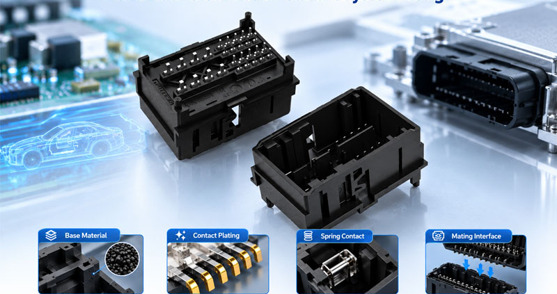
Its performance depends on several interacting design elements: conductive materials, contact geometry, spring characteristics, surface plating, and the mechanical conditions at the mating interface.

A contact with high electrical conductivity may still perform poorly if it cannot maintain sufficient contact force. A corrosion-resistant plating system may wear prematurely if the contact geometry creates excessive friction. Likewise, a mechanically robust terminal may generate excessive heat if the complete current path has inadequate electrical performance.

Reliable automotive contact system design is therefore a balance of electrical, mechanical, thermal, environmental, and manufacturing requirements—not simply a choice of metal.

This guide examines the key design variables, explains how different material systems affect performance, and outlines a practical approach to contact system selection and validation.

Automotive Connector Contact System Design


2.What Is an Automotive Connector Contact System?

A contact system consists of the conductive elements and mating interface that establish an electrical connection.

Depending on the connector architecture, it may include:

  • Contact or terminal base material: Provides electrical conductivity and mechanical strength.
  • Spring contact structure: Maintains the force required for stable mating contact.
  • Contact plating: Controls surface behavior, corrosion protection, wear, and electrical interface performance.
  • Mating interface geometry: Determines how contacts engage and distribute force.
  • Terminal-to-wire termination: Connects the contact system to the conductor through a crimp, weld, or another specified termination method.
  • Retention features: Keep terminals correctly positioned within the connector housing.

These elements perform different functions but must work together.

For example, the mating interface may have suitable initial resistance, yet terminal deformation or loss of spring force can reduce contact stability over time. Similarly, good contact performance cannot compensate for an inadequate wire termination or poor terminal retention.

A complete design should evaluate the entire electrical path, from the wire termination through the terminal body and mating interface to the opposing contact.


3.Selecting Contact Base Materials

The base alloy determines much of a contact’s electrical and mechanical behavior. Material selection should consider conductivity, strength, elastic recovery, stress relaxation, fatigue resistance, stamping capability, and cost.

3.1 Brass

Brass is a copper-zinc alloy commonly used in connector terminals and electrical contact components.

Its potential advantages include:

  • Good manufacturability and formability for suitable grades
  • Practical electrical conductivity
  • Compatibility with established stamping and forming processes
  • Broad availability and cost-effective production

Brass may be suitable for contacts where its mechanical and electrical characteristics meet the application requirements.

However, not every brass grade provides the same conductivity or spring performance. For designs requiring sustained elastic force, engineers must verify the selected alloy and temper rather than relying on the generic material name.


3.2 Phosphor bronze

Phosphor bronze is a copper-based alloy used in many spring-contact applications.

It offers a useful combination of electrical conductivity, strength, formability, and spring behavior, depending on the specific grade and temper.

Potential applications include:

  • Spring contacts
  • Female terminal structures
  • Signal and control interfaces
  • Compact contact systems requiring stable elastic behavior

The main design consideration is the balance between conductivity and mechanical performance. Alloy composition, material thickness, forming geometry, and heat treatment can all influence the final properties.

Phosphor bronze should therefore be selected according to the required force-deflection behavior, current capacity, operating temperature, and expected mechanical life.


3.3 High-strength copper alloys

Some automotive contact designs require greater spring strength, improved stress relaxation resistance, or enhanced fatigue performance.

Specialized copper alloys may be considered when conventional materials cannot meet the combined requirements.

Selection factors include:

  • Conductivity under the specified electrical load
  • Yield strength and elastic recovery
  • Stress relaxation at elevated temperature
  • Resistance to repeated deflection
  • Stamping and forming feasibility
  • Material and processing cost

Higher strength does not automatically mean better overall performance. A material with excellent spring characteristics may have lower conductivity than another candidate. The contact geometry and thermal design must account for this trade-off.


3.4 Comparing common contact materials

Material family Potential advantages Important design considerations
Brass Manufacturability, formability, practical conductivity Grade-dependent strength and spring behavior
Phosphor bronze Balanced conductivity and spring properties Alloy grade, temper, force retention, fatigue
Specialized copper alloys Higher strength or improved stress relaxation for selected designs Conductivity, cost, forming process, application suitability

The values and behavior of specific alloys vary. Final selection should use material datasheets, supplier specifications, and testing of the actual contact design.


4.Contact Plating: Engineering the Mating Surface

The base alloy provides the structural foundation, but the plating system directly affects the surface where current transfers between mating contacts.

Plating can influence corrosion resistance, wear, contact stability, and the durability of the electrical interface. The appropriate finish depends on the signal or power application, environmental exposure, mating cycles, and contact force.

4.1 Tin plating

Tin is commonly used in cost-sensitive automotive electrical interfaces, including many power and general-purpose connections.

Its suitability depends on the contact geometry and operating conditions.

Engineers should consider:

  • Contact force and wiping action
  • Surface oxide behavior
  • Expected mating frequency
  • Vibration and relative contact movement
  • Environmental exposure
  • Plating thickness and process consistency

Tin-plated contacts need a suitable interface design to maintain stable performance. The presence of tin alone does not establish a connector’s current rating or service life.


4.2 Gold plating

Gold is used where surface corrosion resistance and stable low-level electrical contact are important.

It may be considered for sensitive signal interfaces, selected high-cycle applications, and environments where surface degradation could affect performance.

Design factors include:

  • Gold thickness and hardness
  • Underplate selection
  • Contact force
  • Mating cycles
  • Wear at the contact interface
  • Cost and plating coverage

Gold plating is not automatically the best choice for every automotive connector. The appropriate system depends on the actual interface requirements and validated performance.


4.3 Silver plating

Silver has high electrical conductivity and may be used in selected power and high-current contact systems.

However, its suitability depends on the operating environment, surface condition, contact design, and applicable performance requirements.

Environmental exposure and surface-film formation should be considered during material selection and qualification.


4.4 Underplating and plating thickness

The contact finish may contain multiple layers rather than a single surface coating.

A typical system may include:

Base Alloy → Underplate → Functional Contact Finish

The underplate can support corrosion protection, reduce unwanted diffusion between layers, and help stabilize the plating system, depending on the selected materials and process.

Plating specifications should identify the relevant layer materials, thickness requirements, plated areas, and inspection methods.

Where necessary, methods such as X-ray fluorescence (XRF) measurement and metallographic cross-section analysis can help verify plating thickness and layer structure.

The critical point is that plating material, thickness, coverage, and mating-interface design must be evaluated together. A material name alone is not a complete plating specification.


5.Contact Geometry and Spring Force

Contact geometry determines how mating terminals engage, how force is distributed, and how the contact structure responds to mechanical and thermal loading.

Depending on the design, contacts may use cantilever beams, dual-beam structures, box-style receptacles, or other spring geometries.

5.1 Maintaining sufficient contact force

Contact force helps maintain the physical interface between mating surfaces despite small dimensional variations and operational movement.

If force is insufficient, the interface may become more sensitive to vibration, contamination, surface-film effects, and changes in contact resistance.

However, increasing force without considering the complete design can create other problems:

  • Higher mating and unmating forces
  • Greater wear during repeated connection cycles
  • Increased stress on the spring structure
  • More difficult automated assembly
  • Reduced serviceability

The objective is not to maximize force. It is to maintain the specified force range throughout the intended service conditions.


5.2 Elastic range and stress relaxation

A spring contact must operate within a suitable elastic range.

If the contact is permanently deformed during mating or assembly, its ability to maintain the intended force may be reduced.

Elevated temperature can also cause stress relaxation in some materials, gradually reducing spring force under sustained deflection.

Engineers should therefore consider:

  • Maximum and minimum deflection
  • Material yield behavior
  • Contact beam dimensions
  • Forming tolerances
  • Operating temperature
  • Long-term force retention

These factors become especially important in compact connectors, where limited space can make spring geometry more sensitive to manufacturing variation.


5.3 Wiping action and surface wear

Some contact designs create relative sliding movement during mating. This wiping action can help establish a reliable interface by moving across surface films or minor contamination.

However, excessive wiping distance or force can increase friction and plating wear.

The design should balance interface cleaning, contact stability, mating force, and plating durability.

The suitable geometry depends on the finish system, contact materials, environmental conditions, and expected number of mating cycles.


6.Electrical Performance and Thermal Behavior

The contact system must carry the specified current or transmit signals without unacceptable electrical degradation.

For power connections, contact resistance is closely related to heat generation.

The basic relationship is:

[P=I^2R]

Where:

  • (P) is the electrical power dissipated as heat.
  • (I) is the current through the contact.
  • (R) is the relevant electrical resistance.

For illustration, a resistance of 1 mΩ at 50 A produces 2.5 W of resistive heating at that resistance.

This calculation illustrates why resistance control matters, but it does not establish the temperature rise or current rating of a real connector. Actual thermal performance also depends on heat transfer, terminal geometry, conductor size, ambient temperature, neighboring loaded circuits, and mounting conditions.


Design implications

A contact system should be evaluated for:

  • Resistance across the complete intended current path
  • Current distribution through the contact geometry
  • Temperature rise under defined operating conditions
  • Resistance stability after mechanical and environmental exposure
  • Thermal interaction with adjacent terminals and housing materials

A highly conductive base alloy cannot compensate for poor mating geometry, inadequate contact force, or a degraded surface interface.

Likewise, a connector that performs well at room temperature may require additional evaluation at its specified operating temperature.

Current ratings should therefore be based on the connector’s validated specifications and applicable derating requirements—not on material conductivity alone.


7.Matching Contact Materials to Automotive Applications

Different automotive circuits place different demands on the contact system.

7.1 Low-level signal and sensor circuits

Signal circuits may be sensitive to small changes in interface condition, intermittent contact, and electrical noise.

Selection priorities can include:

  • Stable contact behavior at low signal levels
  • Suitable plating and corrosion protection
  • Consistent contact force
  • Dimensional accuracy
  • Resistance to vibration-related degradation

The appropriate finish depends on signal characteristics, environmental conditions, and the connector’s mating requirements.


7.2 Power distribution circuits

Power connections place greater emphasis on current capacity, resistance, and temperature rise.

Important considerations include:

  • Conductivity and contact cross-section
  • Stable contact force
  • Heat dissipation
  • Surface finish compatibility
  • Terminal and wire termination performance
  • Performance under the specified continuous or intermittent load

Material selection should be supported by electrical and thermal validation under representative conditions.


7.3 Compact and high-density connectors

Miniaturized connectors must maintain reliable contact behavior within limited dimensions.

Design challenges may include:

  • Reduced terminal spacing
  • Smaller spring structures
  • Tight dimensional tolerances
  • Restricted heat dissipation
  • Greater sensitivity to terminal alignment
  • Manufacturing consistency at fine pitch

A suitable material must support both the required electrical performance and the mechanical properties needed in the available geometry.


7.4 Vibration-exposed automotive interfaces

Connectors exposed to vibration must maintain stable mating engagement and electrical performance under the specified mechanical loads.

Relevant design factors include spring-force retention, terminal locking, plating durability, contact geometry, and the mechanical load transmitted by the connected harness.

Material selection alone cannot eliminate vibration-related failure. The complete connector assembly and its mounting arrangement must be evaluated through appropriate testing.


8.Manufacturing Factors That Affect Contact System Performance

A well-designed contact system must also be manufactured consistently.

Material properties and geometry can be affected by stamping, forming, plating, assembly, and inspection processes. Variation at any stage may influence the final interface.

8.1 Stamping and forming

Critical characteristics may include:

  • Contact beam dimensions
  • Bend angles and radii
  • Spring height
  • Surface condition
  • Burr direction and size
  • Dimensional consistency

These characteristics can affect mating force, alignment, contact pressure, and the risk of premature wear.


8.2 Plating process control

Plating quality depends on more than the specified material.

Relevant controls may include surface preparation, plating thickness, coverage, adhesion, and consistency across the functional contact area.

The inspection method and acceptance limits should be defined by the product specification and validated manufacturing process.


8.3 Assembly and terminal positioning

During assembly, terminals must be inserted and retained correctly.

Incorrect positioning can affect mating engagement and may prevent the contact system from operating as intended.

Where applicable, terminal position assurance (TPA) features and suitable assembly inspections can help control terminal seating.


8.4 Design for manufacturability

Material selection should be reviewed alongside production feasibility.

Engineers should consider whether the selected alloy can be stamped and formed consistently, whether the plating process can meet the specified requirements, and whether critical characteristics can be inspected at production volume.

A contact system is successful only when its required performance can be reproduced consistently across manufacturing batches.


9.How to Validate an Automotive Connector Contact System

Validation should connect design requirements to measurable results.

The test plan must reflect the intended application, relevant customer specifications, and the connector’s operating environment.

Step 1: Define application requirements

Establish the electrical load, signal characteristics, temperature range, environmental exposure, mating cycles, and mechanical conditions.

Step 2: Review the material and interface design

Confirm the base alloy, temper, plating system, contact geometry, force requirements, and dimensional tolerances.

Step 3: Measure initial electrical and mechanical performance

Depending on the specification, measurements may include contact resistance, mating force, unmating force, terminal retention, and dimensional inspection.

Step 4: Conduct application-relevant validation

Potential tests include:

  • Temperature rise under specified electrical loading
  • Temperature cycling
  • Vibration and mechanical shock
  • Mating durability
  • Corrosion or environmental exposure
  • Contact resistance after conditioning
  • Relevant insulation or dielectric tests for the complete connector

Not every test applies to every design. The required sequence, severity, sample size, and acceptance criteria should follow the approved validation plan.

Step 5: Inspect and compare results

Compare pre-test and post-test measurements, inspect contact surfaces where appropriate, and document any deviation from the defined requirements.

If a failure occurs, use the evidence to investigate the likely mechanism before selecting corrective actions.

Step 6: Verify production consistency

Design validation should be complemented by controls for the manufacturing characteristics that influence performance, including terminal geometry, plating, forming, assembly, and inspection.

This helps establish that the qualified design can be reproduced consistently in mass production.


10.Common Mistakes in Contact System Design

Selecting materials based on conductivity alone

Electrical conductivity is important, but the material must also provide suitable spring properties, fatigue resistance, and manufacturability.

Treating plating as a standalone solution

A corrosion-resistant finish cannot compensate for inadequate contact force, unsuitable geometry, or excessive mechanical movement.

Increasing contact force without considering mating requirements

Excessive force can increase insertion effort, wear, and mechanical stress. The target should be a validated operating range.

Specifying plating without defining thickness and coverage

A plating specification should identify the functional layers and relevant acceptance criteria, not simply state “gold plated” or “tin plated.”

Ignoring manufacturing variation

Small changes in spring height, bend geometry, plating thickness, or terminal position can influence contact behavior. Critical characteristics should be controlled throughout production.

Validating only the initial electrical condition

Initial measurements do not demonstrate long-term performance under vibration, temperature changes, mating cycles, or environmental exposure. Validation should reflect the relevant service conditions.


How FPIC Supports Automotive Connector Development

Automotive connector projects require coordination between electrical requirements, contact geometry, material selection, manufacturing feasibility, and validation planning.

FPIC supports customized automotive connector development and manufacturing, with attention to product requirements, terminal and housing configuration, precision production, electrical testing, and quality control.

For a new project, an engineering review can consider the intended application, connector dimensions, contact arrangement, electrical load, environmental conditions, and applicable customer requirements.

The objective is to align the contact system with the intended application and the production process from the beginning, rather than relying on material selection alone to achieve reliability.


Conclusion

Automotive connector contact system design depends on the interaction between base alloy, plating, spring geometry, contact force, electrical loading, and manufacturing consistency.

Brass, phosphor bronze, and specialized copper alloys can each be appropriate for different designs. Tin, gold, and silver finishes also serve different requirements, depending on the contact interface and operating environment.

The best solution is not necessarily the material with the highest conductivity, the hardest spring, or the most expensive plating. It is the combination that meets the required electrical and mechanical performance throughout the intended service conditions and can be manufactured consistently.

By connecting material selection with geometry, process control, and application-specific validation, engineers can develop automotive connector contact systems with a stronger basis for long-term performance.


FAQ

What materials are commonly used for automotive connector contacts?

Common options include brass, phosphor bronze, and other copper alloys. The final selection depends on conductivity, spring behavior, fatigue resistance, temperature exposure, forming requirements, and cost.

Is gold plating always better than tin plating for automotive connectors?

No. Gold may be appropriate for certain low-level signal interfaces and applications requiring specific corrosion or wear performance. Tin is widely used in many general-purpose and power connections. The correct finish depends on the application, contact geometry, mating requirements, and validation results.

How does contact force affect automotive connector performance?

Contact force helps maintain a stable interface between mating terminals. Insufficient force can increase sensitivity to movement and surface degradation, while excessive force can increase mating effort, wear, and mechanical stress.

Why does contact geometry matter?

Geometry determines how the mating contacts engage, distribute force, and respond to mechanical loading. It also influences current distribution, wear behavior, mating force, and the consistency of the electrical interface.

How can engineers verify contact system performance?

Depending on the application, validation may include contact resistance, mating force, terminal retention, temperature rise, vibration, temperature cycling, mating durability, and corrosion testing. The required methods and acceptance criteria should follow the applicable specification.

Does a highly conductive contact material guarantee a high current rating?

No. Current capacity depends on the complete design, including contact resistance, geometry, terminal cross-section, heat dissipation, ambient conditions, and the number of simultaneously loaded circuits. Ratings must be established through appropriate testing and derating.

What should a contact plating specification include?

It should identify the plating material, layer structure where applicable, thickness requirements, functional coverage, inspection method, and acceptance criteria. The specification should reflect the intended mating interface and operating environment.


Developing a customized automotive connector for your application?

FPIC supports OEM and engineering teams with customized connector development, precision manufacturing, electrical testing, and quality-focused production planning.

Share your connector configuration, electrical requirements, environmental conditions, and project specifications to discuss a suitable development approach.

Contact FPIC to discuss your automotive connector project.


Resources

  1. Würth Elektronik — Trilogy of Connectors: Basic Principles of Connectors

    Engineering reference covering connector materials, contact finishes, copper alloys, and plating processes.

    https://www.we-online.com/en/components/media/o198241v446%20Chapter_1_Trilogy_of_Connectors_2024%20%28rev1%29.pdf

  2. SAE International — ARP6903A: Guide for Achieving Plating/Finishing Compatibility

    Guidance on selecting compatible finishes and platings for connectors and electrical wiring interconnection systems, with consideration of corrosion compatibility.

    https://saemobilus.sae.org/standards/arp6903a-guide-achieving-plating-finishing-compatibility-connectors-accessories-used-electrical-wiring-interconnect-systems-ewis

  3. KYOCERA — Contact (Terminal) and Its Materials

    Overview of common contact materials and the relationship between copper alloys, conductivity, and spring characteristics.

    https://ele.kyocera.com/en/technical/con_contact/

  4. FPIC — How Connector Plating Affects Performance and Lifetime

    Related guidance on plating materials, surface protection, thickness, and connector service life.

    https://fpiconn.com/how-connector-plating-affects-performance-and-lifetime/

  5. FPIC — How Contact Geometry Influences Connector Reliability

    Companion article covering how contact geometry influences mating behavior, electrical performance, and mechanical reliability.

    https://fpiconn.com/how-contact-geometry-influences-connector-reliability/