Tag Archive for: Automotive Connector

How Vibration Affects Automotive Connectors

An automotive connector can pass continuity, contact resistance, insulation, and mating checks during initial inspection and still develop an electrical failure after months or years of vehicle operation.

The reason is that initial testing evaluates the connection at a specific moment. Vehicle vibration, thermal expansion, harness movement, and repeated mechanical stress can gradually change the contact interface, terminal position, locking condition, and surrounding connection system.

Quick Answer:
An automotive connector can pass initial electrical testing but fail after long-term vibration because microscopic movement at the contact interface can cause plating wear, fretting corrosion, and higher contact resistance. Vibration can also affect terminal retention, connector locking, solder joints, and wire-harness strain, eventually causing intermittent or permanent electrical failure.

The key engineering question is therefore not simply:

“Does the connector work now?”

It is:

“Will the electrical interface remain stable after long-term mechanical and environmental stress?”

How Vibration Affects Automotive Connectors


Why Vibration Creates Long-Term Connector Failures

Automotive connectors operate in an environment that is very different from a stationary bench test.

Depending on their location in the vehicle, they may experience combinations of:

  • road-induced vibration;
  • drivetrain and motor vibration;
  • mechanical shock;
  • temperature cycling;
  • cable and harness movement;
  • assembly preload;
  • moisture and contamination;
  • repeated thermal expansion and contraction.

TE Connectivity describes connectors for demanding applications as needing to withstand mechanical stresses that include heavy vibration, while secure locking and positive contact retention are important characteristics for harsh-environment connections.

The critical issue is often not large visible movement of the complete connector.

Instead, very small relative movements may occur between the mating contact surfaces.

These movements can gradually change an interface that initially showed excellent electrical performance.

A simplified failure path is:

Vehicle Vibration → Contact Micro-Movement → Surface Wear → Fretting Corrosion → Contact Resistance Growth → Intermittent or Permanent Failure

Other mechanical paths may occur at the same time:

Vibration → Terminal Movement → Retention Loss

and:

Harness Movement → Connector Load → Housing and Locking Stress

This is why automotive connector vibration reliability must be evaluated as a system rather than as a single material property.

Quality Built Around Customer Requirements


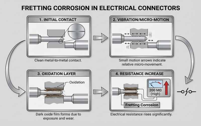
How Contact Micro-Movement Leads to Fretting Corrosion

When male and female terminals mate, electrical current does not necessarily flow uniformly through the entire visible contact surface.

At microscopic scale, current passes through multiple contact points created by the pressure between the mating surfaces.

If vibration or thermal expansion causes repeated small relative movements, the contact surfaces may begin to wear.

This process can:

  1. disturb or remove part of the surface plating;
  2. generate metallic wear debris;
  3. expose material that can oxidize;
  4. reduce the quality of the effective conductive interface;
  5. increase contact resistance.

TE identifies fretting corrosion as a traditional failure mechanism in tin-plated connections and explains that relative movement caused by vibration and thermal expansion can occur between male and female contacts. Its Micro-MaTch design uses an additional positioning spring specifically to absorb this movement.

The important point is that the connector may still appear mechanically intact.

There may be:

  • no broken housing;
  • no visibly bent terminal;
  • no disconnected plug.

Yet electrical resistance at the microscopic contact interface may already be changing.

That is why long-term connector reliability cannot be judged only through visual inspection.


Why Increasing Contact Resistance Matters

A gradual increase in contact resistance can create several consequences.

Voltage Drop

More resistance at the interface increases voltage drop across the connection.

For low-voltage automotive circuits, even relatively small changes may affect sensitive electronics, sensors, control modules, or signal references.

Local Heating

Electrical resistance also creates heat when current flows.

This links vibration reliability directly to thermal reliability.

Vibration itself does not necessarily create significant electrical heat. The thermal risk develops when vibration changes the contact condition and causes resistance to rise.

In higher-current circuits, this can become increasingly important because resistive power loss grows rapidly as current increases.

Intermittent Electrical Signals

Micro-movement can also create temporary changes in contact continuity.

A connector may therefore show:

  • intermittent signal loss;
  • sporadic control faults;
  • communication errors;
  • unstable sensor readings.

These failures can be difficult to diagnose because the connection may work normally when the vehicle is stationary or when the connector is inspected in the workshop.

IEC 60512-2-3 defines a method for determining contact resistance variation under specified dynamic conditions, while IEC 60512-2-5 addresses detection of contact disturbance under dynamic conditions.

This illustrates an important difference between measuring static contact resistance and verifying whether that resistance remains stable during mechanical stress.


Contact Force Must Remain Stable Under Vibration

Contact normal force is one of the key variables that controls the electrical interface.

The female terminal normally incorporates a spring structure that presses against the mating male contact.

That force must be sufficient to maintain a stable conductive interface.

If contact pressure is too low, the system may become more sensitive to:

  • vibration;
  • surface contamination;
  • oxidation;
  • fretting;
  • resistance variation.

However, simply maximizing contact force is not the solution.

Excessive contact load can create other problems, including:

  • higher mating force;
  • accelerated plating wear;
  • greater terminal stress;
  • housing deformation;
  • reduced mating-cycle life.

Molex notes that insufficient pressure increases contact resistance and vulnerability to fretting corrosion and signal dropouts under vibration, while excessive contact load may accelerate plating wear or overstress connector components.

The engineering target is therefore:

Stable Contact Force + Controlled Mating Force + Long-Term Electrical Reliability

This is particularly important in multi-contact automotive connectors where the operating force of many individual terminals combines into the total connector mating force.


Mating Force and Contact Force Are Not the Same

These terms are sometimes treated as interchangeable, but they describe different aspects of connector performance.

Contact normal force is the mechanical pressure acting at the electrical contact interface.

Connector mating force is the total force required to engage the complete connector.

Total mating force can include contributions from:

  • terminal spring force;
  • contact friction;
  • seals;
  • housing alignment;
  • locking structures;
  • multiple simultaneously engaging terminals.

A connector may therefore be optimized for lower operating effort while still maintaining sufficient contact pressure.

The objective is not simply to make a connector “tight.”

The objective is to create a predictable mechanical interface that maintains stable electrical contact over the intended service life.


Terminal Retention Is a Separate Reliability Requirement

Contact force controls the interface between mating conductive surfaces.

Terminal retention performs a different job.

It keeps the terminal correctly positioned inside the connector housing.

This distinction is important because an electrically good contact cannot remain reliable if the terminal begins to move backward inside the housing.

Under vibration or wire-harness load, insufficient retention may result in:

  • terminal back-out;
  • reduced mating depth;
  • partial contact engagement;
  • intermittent continuity;
  • complete circuit interruption.

Molex describes contact retention as the mechanical means used to keep connector elements secured so electrical continuity can be maintained under stresses such as vibration and thermal cycling.

Design FactorPrimary Function
Contact normal forceMaintains the conductive contact interface
Terminal retentionKeeps the terminal correctly seated in the housing
Connector lockingKeeps plug and receptacle fully mated

A robust automotive connector must control all three.


How TPA and CPA Improve Connector Security

Automotive connectors frequently use additional locking or assurance structures.

A primary terminal lock normally retains the contact inside the housing, while secondary systems can provide additional security.

Two terms commonly used in automotive connector design are:

TPA — Terminal Position Assurance

TPA helps verify and secure the correct position of terminals inside the connector housing.

Its purpose is to reduce the risk of a terminal being incompletely inserted or moving out of its intended position.

CPA — Connector Position Assurance

CPA helps confirm and secure the mated condition of the connector itself.

Its purpose is different from terminal retention: it acts at the plug-to-receptacle connection level.

FPIC’s automotive connector technical materials distinguish CPA as a connector-position assurance structure and TPA as a terminal-position assurance structure.

These secondary structures are particularly valuable where vibration, harness loads, difficult assembly access, or safety requirements make incomplete engagement unacceptable.


Housing and Locking Design Matter Under Vibration

An automotive connector housing is not simply a plastic shell.

It performs several mechanical functions simultaneously:

  • terminal positioning;
  • mating guidance;
  • polarization;
  • retention;
  • connector locking;
  • protection against mismating;
  • environmental sealing where required.

A well-designed terminal cannot provide reliable service if the housing allows excessive relative movement or the connector lock disengages under vibration.

For harsh environments, TE highlights secure locking and positive contact-retention systems as important characteristics of rugged connectors.

Engineers should therefore evaluate:

  • primary latch geometry;
  • secondary locking;
  • CPA design where required;
  • housing stiffness;
  • material creep and stress relaxation;
  • connector-to-device mounting;
  • seal compression;
  • tolerance accumulation;
  • mating alignment.

The complete locking architecture must remain stable throughout the expected mechanical and environmental lifecycle.


Harness Strain Can Amplify Connector Stress

The connector does not operate independently from the wire harness.

This is especially important in automotive applications.

A wire harness can introduce mechanical forces through:

  • cable weight;
  • routing tension;
  • tight bending;
  • engine or vehicle movement;
  • incorrect clip spacing;
  • assembly preload;
  • unsupported cable length;
  • vibration transmitted along the conductors.

If the harness is not properly supported, these forces can reach the rear of the connector and eventually affect the terminals.

A simplified mechanical path is:

Harness Movement → Cable Load → Terminal Stress → Contact Micro-Movement

For this reason, automotive connection reliability should consider the complete relationship between:

  • connector;
  • terminal;
  • conductor;
  • seal;
  • strain relief;
  • harness clips;
  • cable exit direction;
  • equipment mounting.

Cable Exit Direction

A harness that leaves the connector at an unsuitable angle can continuously load the terminal or housing.

Bend Radius

Forcing the cable into a very tight bend near the connector can introduce long-term mechanical stress.

Harness Fixing Points

Correctly positioned clips or supports reduce the amount of cable movement transferred to the connector.

Conductor Size

Larger conductors have greater stiffness and can transmit more mechanical force to the connection.

This is one reason why connector and wire-harness engineering should be considered together rather than purchased as completely independent components.


PCB Headers Have Additional Vibration Risks

Automotive PCB connectors require another level of analysis.

For a wire-to-wire connector, engineers primarily consider:

Harness → Terminal → Contact → Housing → Connector Lock

A PCB header adds another chain:

Receptacle → Header Contact → PCB Pin → Solder Joint → PCB

This introduces additional potential vibration interfaces.

Pin Position and Alignment

Poor pin positioning can create mechanical preload during mating or soldering.

Solder-Joint Stress

Vibration transmitted through the connector body can eventually reach the solder joints.

PCB Movement

The printed circuit board itself can flex under vibration.

Housing Retention

The header housing must remain mechanically stable relative to the PCB.

Harness Leverage

A harness attached to the mating receptacle may create bending or leverage forces on the header.

This is particularly important in control modules, lighting systems, power-seat electronics, window-control modules, multimedia systems, and other vehicle electronics.

For an automotive PCB connector, vibration reliability is a system property rather than a terminal-only property.

FPIC’s internal automotive connector materials define header connectors as structures containing fixed male contacts that normally connect to the PCB or directly to internal equipment circuits.

This is why PCB-header validation should consider both contact reliability and board-level mechanical integrity.


Terminal Material Influences Vibration Performance

Automotive terminal material selection requires a balance between electrical and mechanical properties.

Important characteristics include:

  • electrical conductivity;
  • spring strength;
  • yield behavior;
  • fatigue resistance;
  • formability;
  • stress-relaxation resistance;
  • corrosion behavior.

Typical connector contact materials include different copper alloys selected according to application requirements.

A highly conductive material alone may not be sufficient if it cannot maintain the required spring behavior after repeated mechanical and thermal stress.

Conversely, a highly elastic material may introduce unnecessary electrical resistance or cost if used without considering current and signal requirements.

The terminal geometry, material, heat treatment, contact pressure, and plating system should therefore be developed together.


Plating Selection Affects Fretting Resistance

Contact plating influences:

  • resistance;
  • wear;
  • oxidation;
  • corrosion;
  • friction;
  • mating durability.

Gold and tin are widely used in connector systems, but they behave differently.

Molex recommends carefully matching contact finishes and notes that tin-to-tin systems require validation for fretting corrosion, oxidation, and related long-term effects, while mismatched gold-to-tin interfaces can introduce additional reliability risk.

This does not mean that one plating material is universally better.

The appropriate system depends on:

  • signal or power level;
  • contact force;
  • environment;
  • mating-cycle requirement;
  • temperature;
  • vibration;
  • cost;
  • customer specification.

The important principle is:

Plating should be selected as part of the contact system, not as an isolated specification.


Why Initial Electrical Testing Is Not Enough

Initial testing is essential.

But it answers only part of the reliability question.

Initial tests can verify:

  • continuity;
  • contact resistance;
  • insulation resistance;
  • withstand voltage;
  • pin position;
  • dimensional conformity.

These measurements answer:

“Does the connector meet requirements now?”

Reliability testing asks a different question:

“Will the connector still meet those requirements after mechanical and environmental stress?”

That distinction is fundamental.

A connector may initially have:

  • correct contact force;
  • low resistance;
  • proper terminal seating;
  • correct housing lock.

Long-term vibration can gradually change one or more of these conditions.

Therefore, a robust validation program should compare electrical and mechanical performance before and after stress, and in some cases monitor electrical continuity while the stress is being applied.


How Vibration Testing Should Be Evaluated

A vibration test should not be treated simply as:

Run the machine for a specified number of hours and check whether the connector broke.

A useful validation plan defines what must be measured before, during, and after the test.

Before Vibration Testing

Typical checks may include:

  • visual inspection;
  • terminal position;
  • locking condition;
  • contact resistance;
  • continuity;
  • mating condition;
  • dimensional checks where necessary.

During Vibration Testing

Depending on the specification, the test may monitor:

  • transient discontinuity;
  • contact disturbance;
  • resistance variation;
  • connector movement.

IEC 60512-6-5 defines a method intended to assess the ability of components to withstand specified levels of random vibration.

IEC 60512-2-3 covers contact-resistance variation under dynamic conditions, while IEC 60512-2-5 addresses contact disturbance.

The exact test severity, mounting arrangement, frequency range, acceleration, duration, monitoring requirements, and acceptance limits must follow the applicable product specification or customer requirement.

After Vibration Testing

The connector should be evaluated again for possible changes such as:

  • increased contact resistance;
  • terminal back-out;
  • housing damage;
  • lock deterioration;
  • contact wear;
  • seal displacement;
  • wire or crimp damage;
  • solder-joint damage in PCB applications.

The engineering value comes from comparing the connector condition before and after exposure.

Vibration and Thermal Cycling Should Be Considered Together

Vehicles do not experience vibration in isolation.

Temperature also changes during operation.

Different materials expand and contract at different rates, including:

  • copper-alloy terminals;
  • plastic housings;
  • PCB laminates;
  • seals;
  • wire insulation;
  • connector plating.

Repeated temperature changes can therefore create additional relative movement between contact surfaces.

TE specifically identifies vibration and thermal expansion as sources of relative contact movement associated with fretting-corrosion risk.

This interaction explains why a connector that performs acceptably in a short room-temperature mechanical test may require broader environmental validation for automotive use.

Depending on the application, a reliability plan may therefore combine:

  • vibration;
  • thermal cycling;
  • thermal shock;
  • humidity;
  • salt spray;
  • electrical measurements.

Crimp Quality Also Influences Vibration Reliability

For wire-to-connector applications, the crimp is another critical mechanical and electrical interface.

A properly controlled crimp should provide a stable connection between the conductor and terminal.

Important controls can include:

  • conductor crimp height;
  • crimp width;
  • conductor position;
  • insulation support;
  • bellmouth condition;
  • strand integrity;
  • pull force;
  • crimp cross-section.

An excessively loose crimp may allow conductor movement.

An excessively tight crimp can damage strands or weaken the conductor.

Either condition may reduce the connection’s ability to tolerate vibration.

FPIC’s internal crimping standards include controls for conductor crimp height, insulation crimping, conductor position, pull-force testing, and cross-section analysis.

This reinforces an important reliability principle:

The terminal contact and the wire termination must both remain mechanically stable.


A Practical Automotive Connector Reliability Checklist

Before selecting or developing an automotive connector, engineers should define the complete operating environment.

Design AreaQuestions to Confirm
Electrical circuitSignal, low-current power, or higher-current circuit?
Contact systemWhat normal force and contact geometry are required?
Terminal materialDoes it balance conductivity and spring performance?
PlatingIs it suitable for vibration, wear, environment, and lifecycle?
Terminal retentionHow is terminal back-out prevented?
Connector lockingIs primary or secondary locking required?
PCB interfaceIs it wire-to-wire, wire-to-board, or PCB header?
HarnessWhat conductor size, cable weight, and exit direction apply?
Strain reliefHow is harness movement isolated from the terminals?
EnvironmentWhat vibration, temperature, moisture, and contamination occur?
TestingWhat electrical measurements are required before and after vibration?
ProductionHow are terminal position, crimping, assembly, and traceability controlled?

A complete specification helps prevent the common mistake of evaluating vibration resistance as a single connector feature.


How FPIC Supports Automotive Connector Reliability

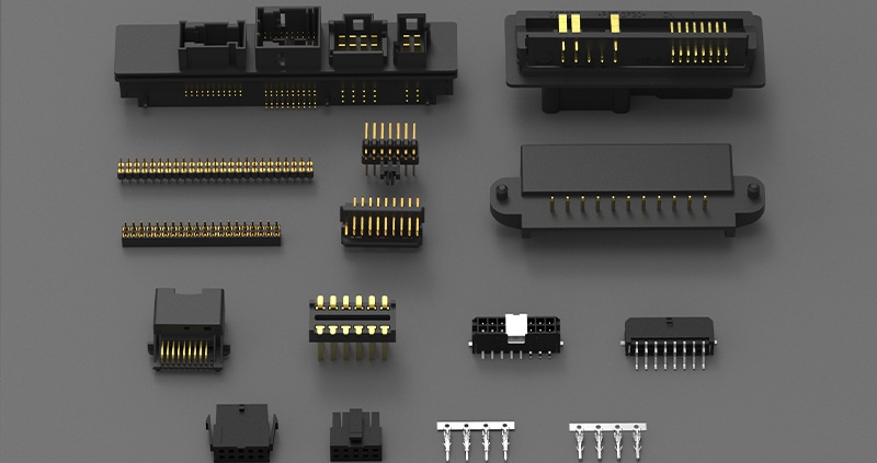
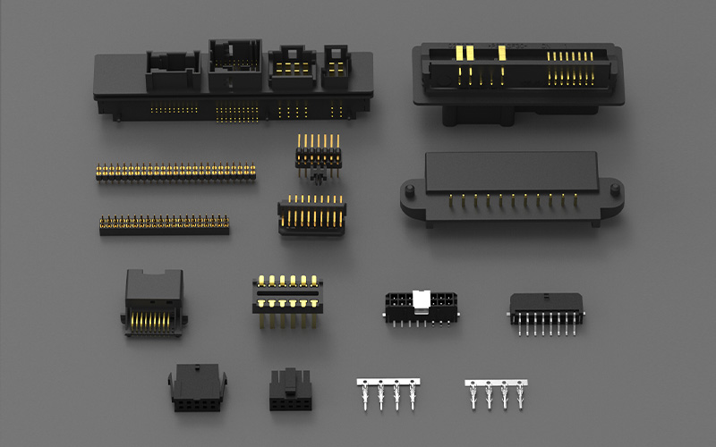
FPIC supports customized automotive low-voltage connectors, automotive PCB headers and receptacles, terminals, stamped components, and related cable assemblies.

Our automotive connector development and manufacturing capabilities cover multiple stages of the connection system.

Contact and Terminal Development

FPIC supports terminal structure, material, plating, retention, and manufacturing evaluation according to the application requirements.

Housing and Locking Development

Connector housing, keying, terminal retention, mating alignment, and locking structures can be evaluated during custom product development.

Automotive PCB Headers

FPIC develops customized board-side automotive connector solutions for vehicle electronic modules, including applications such as lighting control, power seats, window-lift systems, multimedia, and related control electronics.

Wire Harness Integration

Where the project requires a complete connection assembly, connector, terminal, conductor, crimping, strain relief, and harness routing requirements can be evaluated together.

In-House Manufacturing Processes

FPIC’s manufacturing platform includes:

  • precision stamping;
  • plastic injection molding;
  • insert molding;
  • tooling development;
  • automated connector assembly;
  • wire processing;
  • cable assembly;
  • CCD-supported inspection.

Reliability Testing

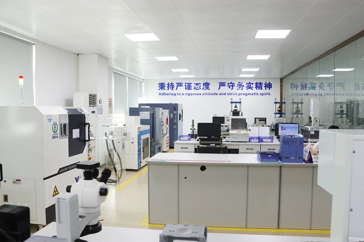
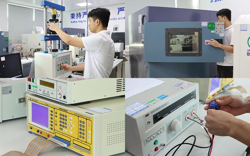
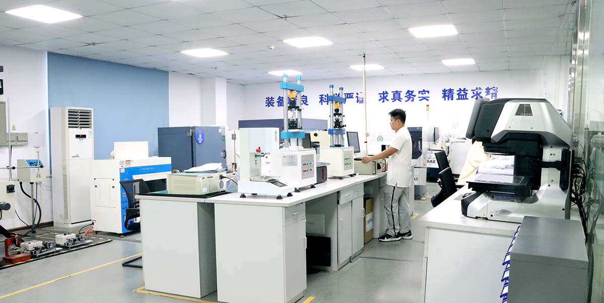
FPIC’s internal laboratory capability includes equipment for:

  • contact impedance testing;
  • insertion and extraction force testing;
  • temperature-rise testing;
  • vibration testing;
  • thermal shock;
  • withstand voltage;
  • insulation testing;
  • dimensional measurement;
  • X-ray inspection.

FPIC’s technical materials also identify automotive connector validation areas including contact resistance, temperature rise, mating force, terminal retention, vibration, high- and low-temperature exposure, temperature/humidity cycling, solder-heat resistance, and salt spray.

Company capability materials list vibration equipment, contact-impedance testers, temperature-rise testers, insertion/extraction-force equipment, thermal-shock chambers, X-ray systems, and dimensional inspection equipment.

For automotive projects, FPIC operates under IATF 16949 and supports product-development and manufacturing controls appropriate to customized automotive connector programs.

The objective is not merely to manufacture a connector that passes an initial continuity check.

It is to establish a controlled development and production process that supports stable connection performance through the intended operating environment.


Frequently Asked Questions

1. Why can an automotive connector pass continuity testing but fail under vibration?

Initial continuity testing confirms that the electrical path is complete at the time of measurement. Long-term vibration can create microscopic contact movement, plating wear, fretting corrosion, terminal movement, or locking stress that gradually changes the connection and may eventually cause intermittent or permanent failure.

2. What is fretting corrosion in an automotive connector?

Fretting corrosion is degradation that occurs when loaded mating surfaces experience very small repeated relative movements. In electrical contacts, this movement can disturb plating, generate wear debris and oxidation products, and increase contact resistance.

3. How does vibration increase connector contact resistance?

Vibration can create repeated micro-movement at the contact interface. Over time, this may wear the contact surface, change the effective conductive contact area, and promote oxidation or fretting debris, causing resistance to increase.

4. What prevents an automotive terminal from backing out?

Terminal retention normally depends on the primary terminal-locking structure, correct terminal insertion, and, in many automotive systems, a secondary Terminal Position Assurance (TPA) feature.

5. What is the difference between TPA and CPA?

TPA helps secure and verify terminal position inside the connector housing. CPA helps secure and verify the fully mated position of the plug and receptacle.

6. Does higher contact force always improve vibration reliability?

No. Insufficient force can increase resistance and micro-movement risk, but excessive contact force may increase mating effort, wear, and spring stress. The contact system should be optimized for stable force throughout the required service life.

7. Why does the wire harness affect connector vibration reliability?

The harness can transfer cable weight, bending force, and vibration into the connector. Improper routing, insufficient strain relief, or unsuitable fixing points can increase load on the terminal and contact interface.

8. Are automotive PCB headers affected by vibration differently from wire-to-wire connectors?

Yes. PCB headers introduce additional interfaces such as header pins, solder joints, PCB movement, and board mounting. Their vibration reliability must therefore be evaluated at both the contact and PCB levels.


Conclusion

Automotive connector reliability cannot be judged only by whether a new connector passes an initial electrical test.

Long-term vibration can affect several parts of the connection system:

Contact Interface → Terminal Retention → Housing Locking → PCB Interface → Wire Harness

Microscopic contact movement can lead to fretting corrosion and resistance growth. Terminal movement can reduce mating depth. Harness strain can transfer mechanical loads into the connector. PCB headers introduce additional solder-joint and board-level stresses.

For this reason, reliable automotive connection design requires electrical, mechanical, material, harness, and validation requirements to be considered together.

FPIC supports automotive connector projects from terminal and housing development through PCB-header design, cable integration, tooling, manufacturing, testing, and repeat production.


Discuss Your Automotive Connector Project

Developing a customized automotive connector, PCB header, terminal, or related cable assembly?

Send FPIC your 2D or 3D drawings, electrical requirements, mating interface, wire specification, operating environment, validation requirements, and forecast demand for engineering evaluation.

Email: info@fpiconn.com


Resources

  • TE Connectivity — Micro-MaTch Miniature Ribbon Cable Connectors and Fretting Corrosion Resistance.
  • TE Connectivity — Rugged Connectors for Harsh Conditions.
  • Molex — Engineering Contact Engagement and Normal Force for Connector Performance.
  • Molex — Connector Contact Retention Guide.
  • Molex — Gold or Tin vs. Gold and Tin Contact Finishes.
  • IEC 60512-2-1 — Contact Resistance — Millivolt Level Method.
  • IEC 60512-2-3 — Contact Resistance Variation Under Dynamic Conditions.
  • IEC 60512-2-5 — Contact Disturbance Under Dynamic Conditions.
  • IEC 60512-6-5 — Random Vibration Test Method.
Connector Failure Analysis in Vehicles

Automotive connectors are designed to operate reliably for more than a decade under demanding conditions. However, many field failures are not caused by design flaws alone, but by a combination of environmental stress, installation conditions, and long-term degradation mechanisms.

Understanding how and why connectors fail is critical for improving system reliability, reducing warranty costs, and optimizing design decisions early in development.

Among the most common and impactful failure mechanisms in vehicles are fretting corrosion, water ingress, and thermal stress. These factors often act together, accelerating degradation beyond what isolated testing may predict.


Why Connector Failure Analysis Matters

Connector failures rarely occur as sudden events. Most are the result of gradual degradation processes that evolve over time.

Without proper failure analysis:

  • root causes may be misidentified
  • corrective actions may be ineffective
  • the same issues may repeat across projects

A structured failure analysis approach helps engineers link symptoms to underlying mechanisms and implement targeted improvements.

Connector Failure Analysis in Vehicles


Fretting Corrosion: The Hidden Failure Mechanism

Fretting corrosion is one of the most common causes of intermittent electrical failure in automotive connectors.

How It Happens

  • vibration causes micro-motion between contact surfaces
  • protective plating wears away
  • oxide debris forms at the interface
  • electrical resistance increases

This process is often invisible from the outside, making it difficult to detect during inspection.


Typical Symptoms

  • intermittent signal loss
  • unstable electrical performance
  • increased contact resistance
  • no visible mechanical damage

Where It Occurs

  • engine bay connectors
  • chassis-mounted harnesses
  • high-vibration zones

Water Ingress: The Silent Reliability Killer

Water ingress occurs when moisture penetrates the connector interface or wiring system.

Causes

  • insufficient sealing design
  • damaged or misassembled seals
  • improper connector orientation
  • aging of sealing materials

Effects

  • corrosion of terminals
  • increased contact resistance
  • short circuits or leakage paths
  • long-term degradation of insulation

High-Risk Scenarios

  • underbody applications
  • areas exposed to road spray or pressure washing
  • connectors with compromised sealing integrity

Even connectors with high IP ratings can fail if sealing is not maintained during assembly or service.


Thermal Stress: Long-Term Degradation Driver

Thermal stress results from repeated temperature changes and heat generation during operation.

Sources

  • ambient temperature variation
  • heat from nearby components
  • current-induced heating (I²R losses)

Effects on Connectors

  • material expansion and contraction
  • loss of contact force
  • seal degradation
  • accelerated aging of materials

Combined Effects

Thermal stress often amplifies other failure mechanisms:

  • increased temperature accelerates corrosion
  • material softening reduces mechanical stability
  • cycling creates micro-movements that lead to fretting

Why Failures Are Often Multi-Factor

In real automotive environments, failures are rarely caused by a single factor.

For example:

  • vibration → fretting corrosion
  • moisture → oxidation
  • temperature → material degradation

These factors interact, creating compounded effects that are more severe than individual stresses.

This is why connectors that pass standard tests may still fail in field conditions.


Failure Analysis Methods

A systematic approach to connector failure analysis typically includes:

Visual Inspection

  • check for corrosion, discoloration, or damage

Electrical Testing

  • measure contact resistance
  • check continuity and insulation

Microscopic Analysis

  • identify fretting wear or oxide layers

Environmental Testing

  • reproduce failure under controlled stress conditions

Prevention Strategies

Design Level

  • select appropriate materials and plating
  • ensure sufficient contact force
  • design for sealing and environmental protection

System Level

  • optimize harness routing to reduce vibration
  • avoid water accumulation points
  • ensure proper connector orientation

Manufacturing and Assembly

  • ensure correct seal installation
  • maintain consistent crimp quality
  • control assembly processes

Validation

  • include combined stress testing
  • simulate real installation conditions
  • perform long-term aging tests

How FPIC Supports Failure Prevention

Preventing connector failure requires integration across design, manufacturing, and validation.

FPIC supports customers with:

  • connector and harness design optimization
  • sealing and routing strategy review
  • controlled assembly processes
  • validation aligned with real-world conditions

By addressing failure mechanisms early, long-term reliability can be significantly improved.


Final Thoughts

Connector failures in vehicles are rarely random. They are the result of predictable physical and environmental processes.

Fretting corrosion, water ingress, and thermal stress are among the most critical factors affecting long-term reliability—and they often work together.

Understanding these mechanisms allows engineers to move from reactive troubleshooting to proactive design improvement.


FAQ

What is the most common cause of connector failure in vehicles?

Fretting corrosion caused by vibration is one of the most common causes, especially in high-vibration environments.

Can sealed connectors prevent all water ingress issues?

No. Sealing effectiveness depends on design, assembly quality, and long-term material performance.

How does temperature affect connector reliability?

Thermal cycling can reduce contact force, degrade materials, and accelerate other failure mechanisms.

Why do connectors fail even after passing tests?

Because real-world conditions often involve combined stresses that are not fully replicated in standard testing.

How can connector failures be reduced?

Through proper design, material selection, assembly control, and realistic validation testing.


CTA

Reduce Connector Failure Risk in Your System

Understanding failure mechanisms is the first step toward building reliable systems.

FPIC provides connector and wire harness solutions designed for real-world conditions, helping reduce failure risk and improve long-term performance.

Contact us to discuss your application challenges.


Resources

  1. USCAR-2 – Automotive Connector Performance Specification: defines durability and environmental testing methods for connectors.
  2. TE Connectivity – Fretting Corrosion in Electrical Contacts: explains vibration-induced degradation mechanisms.
  3. Molex – Sealed Connector Design and Water Ingress: discusses sealing strategies and failure risks.
  4. Amphenol – Thermal Effects on Connector Systems: covers temperature-related reliability challenges.
  5. IEC 60512 – Connector Testing Standards: provides standard test methods for electrical connectors.
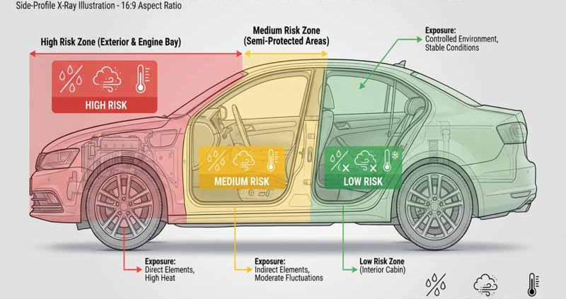
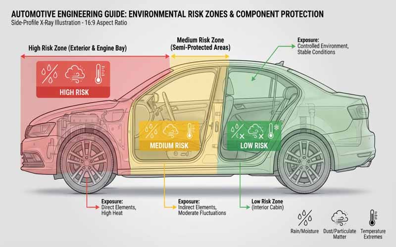
Automotive connectors installation zones and environmental exposure

In automotive electrical systems, connectors selection is not only about current rating or pin count. One of the most critical decisions is whether to use a sealed or unsealed connector.

This choice directly affects reliability, cost, assembly complexity, and long-term performance. Selecting the wrong type for a given installation zone can lead to corrosion, signal issues, or premature failure.

This article explains the differences between sealed and unsealed connectors, and how to select the right type based on real automotive installation environments.


What Are Sealed and Unsealed Connectors?

Sealed Connectors

Sealed connectors are designed to prevent the ingress of water, dust, and contaminants. They typically include:

  • wire seals (grommets)
  • interface seals (between connector halves)
  • housing features that maintain compression

They are commonly rated using IP (Ingress Protection) standards such as IP67 or IP69K.


Unsealed Connectors

Unsealed connectors do not include environmental sealing features. They are:

  • simpler in design
  • easier to assemble
  • more cost-effective

They rely on installation in protected environments where exposure to moisture or contaminants is minimal.

Automotive Installation Zones Diagram


Why Installation Zone Matters

The key factor in connector selection is not the connector itself—but where it is installed.

Automotive systems can be divided into several environmental zones, each with different risk levels.


Typical Automotive Installation Zones

Zone 1: Exterior / Underbody / Engine Bay

Examples:

  • engine compartment
  • underbody harnesses
  • wheel area sensors

Environmental Conditions:

  • water splash and immersion
  • mud, salt, and chemicals
  • high temperature variation
  • strong vibration

Recommendation:
Use sealed connectors with high IP ratings (IP67 or higher).

Failure to use sealing in this zone will almost certainly lead to corrosion and electrical failure.


Zone 2: Semi-Protected Areas

Examples:

  • trunk area
  • door interiors
  • near HVAC systems

Environmental Conditions:

  • occasional moisture
  • condensation
  • moderate temperature variation

Recommendation:
Use sealed connectors or partially sealed designs, depending on risk level.

Designers should consider worst-case conditions such as water ingress or condensation buildup.


Zone 3: Interior Cabin (Protected Zone)

Examples:

  • dashboard electronics
  • infotainment systems
  • interior wiring

Environmental Conditions:

  • stable temperature
  • minimal moisture
  • low contamination risk

Recommendation:
Use unsealed connectors for cost efficiency and ease of assembly.

Sealed connectors in this zone may increase cost without providing meaningful benefits.


Understanding IP Ratings

Sealed connectors are often classified using IP ratings.

For example:

  • IP67: protected against dust and temporary water immersion
  • IP68: protected against continuous immersion (depending on specification)
  • IP69K: resistant to high-pressure, high-temperature water spray

However, IP rating alone does not guarantee long-term reliability. It reflects test conditions, not full lifecycle performance.


Trade-Offs Between Sealed and Unsealed Connectors

Sealed Connectors

Advantages:

  • protection against water and contaminants
  • improved long-term reliability in harsh environments
  • reduced risk of corrosion

Challenges:

  • higher cost
  • more complex assembly
  • higher insertion force
  • more difficult serviceability

Unsealed Connectors

Advantages:

  • lower cost
  • easier assembly and maintenance
  • lower insertion force
  • simpler design

Challenges:

  • limited environmental protection
  • higher risk if used in incorrect location

Common Design Mistakes

Over-Specifying Sealing

Using sealed connectors in low-risk environments:

  • increases cost unnecessarily
  • complicates assembly
  • reduces efficiency

Under-Specifying Protection

Using unsealed connectors in harsh environments:

  • leads to corrosion and failure
  • causes intermittent electrical issues
  • increases warranty risk

Ignoring Real Installation Conditions

Design decisions based only on CAD layout rather than real-world exposure can lead to incorrect connector selection.


Beyond Sealing: System-Level Considerations

Connector reliability depends on more than sealing alone.

Other critical factors include:

  • harness routing (water accumulation risk)
  • drainage paths
  • connector orientation
  • strain relief and fixation
  • ventilation vs sealing balance

A sealed connector installed incorrectly can still fail.


How FPIC Supports Connector Selection

Selecting the right connector requires understanding both the product and the application environment.

FPIC supports customers with:

  • connector selection based on installation zones
  • custom wire harness integration
  • sealing and protection strategy review
  • design for manufacturability (DFM)
  • validation support under real conditions

By aligning connector design with real-world usage, reliability risks can be significantly reduced.


Final Thoughts

Choosing between sealed and unsealed connectors is a fundamental decision in automotive design.

The correct approach is not to always choose the most robust option—but to match the connector type to the installation environment.

A well-balanced design considers:

  • environmental exposure
  • cost efficiency
  • assembly complexity
  • long-term reliability

Understanding installation zones is the key to making the right decision.


FAQ

What is the main difference between sealed and unsealed connectors?

Sealed connectors include features that prevent water and dust ingress, while unsealed connectors do not.

Are sealed connectors always better?

No. They are necessary in harsh environments but may add unnecessary cost and complexity in protected areas.

What IP rating is typically required for automotive applications?

IP67 is common for exterior applications, while higher ratings like IP69K may be required for extreme conditions.

Can unsealed connectors be used in vehicles?

Yes, they are widely used in interior and protected zones.

What is the biggest risk in connector selection?

Using the wrong connector type for the installation environment.


Choose the Right Connector for Your Application

Selecting the correct connector type early in the design process can prevent costly failures and redesigns.

FPIC provides connector and wire harness solutions tailored to real automotive environments, balancing reliability, cost, and manufacturability.

Contact us to discuss your project requirements.


Resources

  1. IEC 60529 – IP Rating Standard: defines ingress protection levels for dust and water resistance.
  2. USCAR-2 – Automotive Connector Performance Specification: includes environmental and durability testing requirements.
  3. TE Connectivity – Sealed vs Unsealed Connector Design: explains design differences and application scenarios.
  4. Molex – Automotive Sealed Connector Systems: provides examples of sealed connector technologies and applications.
  5. Amphenol – Automotive Interconnect Solutions: covers connector design considerations for harsh environments.

In automotive electrical systems, Automotive connectors performance is often evaluated based on initial specifications—contact resistance, current capacity, and mechanical retention. However, long-term reliability is not determined at time zero. It is shaped by how these parameters evolve over time.

One of the most critical yet often underestimated factors is contact resistance drift.

Contact resistance drift refers to the gradual increase or fluctuation of resistance at the electrical interface between mating terminals. While the change may be small in absolute terms, its impact can be significant—especially in high-current, high-voltage, and signal-sensitive automotive systems.


Understanding Contact Resistance at the Interface Level

Electrical contacts are not perfectly smooth surfaces. Even highly polished terminals only touch at microscopic asperities.

This means:

  • the real contact area is much smaller than the apparent area
  • current flows through discrete micro-contact points
  • resistance is highly sensitive to surface condition and contact force

Any change in these micro-contact conditions—such as oxidation, wear, or reduced contact pressure—can increase resistance.

Over time, these small changes accumulate, resulting in measurable resistance drift.


Why Contact Resistance Drift Matters

Heat Generation and Thermal Runaway Risk

In power circuits, resistance increase leads directly to higher heat generation (I²R losses). This can create a feedback loop:

  • higher resistance → more heat
  • more heat → faster material degradation
  • degradation → further resistance increase

In severe cases, this can lead to localized overheating or even thermal runaway in high-power systems.

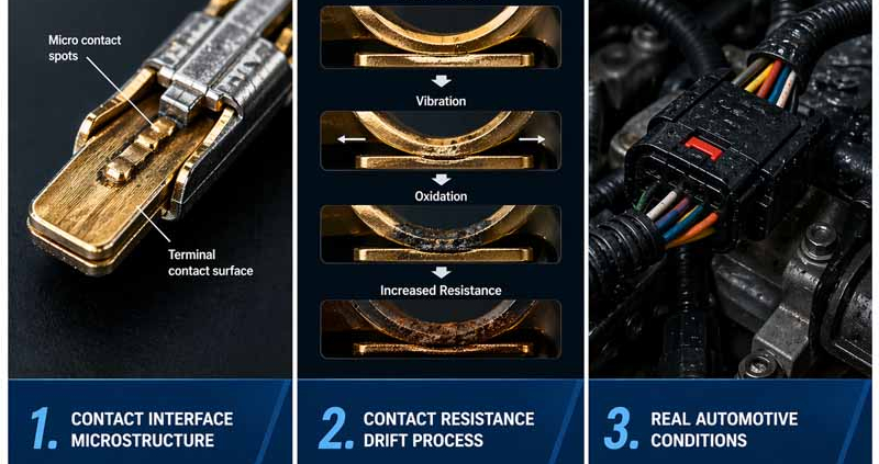
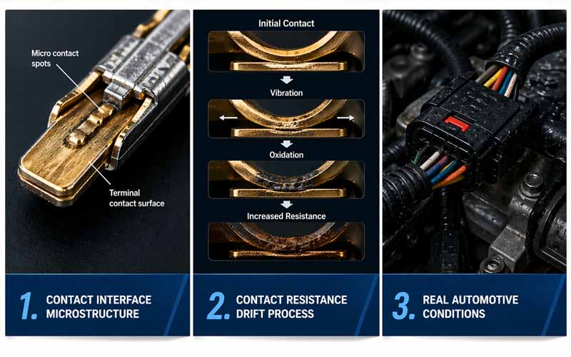
Contact Interface Microstructure


Voltage Drop and Efficiency Loss

In EV and power distribution systems, even a small resistance increase can result in:

  • measurable voltage drop
  • reduced energy efficiency
  • performance degradation in motors or inverters

As system voltages rise, maintaining stable connections becomes even more critical.


Signal Integrity Degradation

For low-current signal circuits, resistance drift affects:

  • signal amplitude
  • noise margin
  • communication stability

This is particularly important in CAN, LIN, and automotive Ethernet systems, where stable electrical characteristics are required for reliable data transmission.


Root Causes of Contact Resistance Drift

Contact resistance drift rarely has a single cause. It is typically the result of multiple interacting factors.

Fretting Corrosion

Micro-motion between contact surfaces caused by vibration leads to:

  • wear of protective plating
  • formation of oxide debris
  • increased contact resistance

This is one of the most common failure mechanisms in automotive connectors.


Oxidation and Environmental Exposure

Exposure to oxygen, humidity, and contaminants can form insulating layers on contact surfaces.

Key risk factors include:

  • unsealed connectors
  • harsh environmental conditions
  • long service life

Loss of Contact Force

Contact force is critical for maintaining a stable electrical interface. Over time, it can decrease due to:

  • material creep
  • thermal cycling
  • stress relaxation

Reduced force leads to smaller effective contact area and higher resistance.


Plating Degradation

Surface plating (tin, silver, or gold) is designed to protect against corrosion and ensure conductivity. However:

  • repeated mating cycles can wear plating
  • vibration can accelerate degradation
  • base materials may oxidize once exposed
  • Contact Resistance Drift Process

Real-World Conditions Accelerate Drift

Laboratory testing often evaluates connectors under controlled conditions. However, real automotive environments introduce combined stresses:

  • continuous vibration from road conditions
  • wide temperature fluctuations
  • moisture, dust, and chemicals
  • harness movement and mechanical strain

These factors do not act independently—they interact and accelerate degradation mechanisms.

As a result, contact resistance drift in real applications is often faster and more complex than predicted by isolated testing.


High-Risk Automotive Applications

High-Current Systems

  • battery connections
  • inverter interfaces
  • power distribution units

These systems are sensitive to heat and efficiency loss.


High-Speed Data Systems

  • ADAS sensors
  • communication networks
  • control modules

These systems are sensitive to signal degradation.


Safety-Critical Systems

  • braking systems
  • airbag systems
  • vehicle control electronics

In these applications, even intermittent resistance variation can lead to unacceptable risk.


Strategies to Control Contact Resistance Drift

Optimize Contact Design

  • maintain stable contact force over time
  • design for vibration resistance
  • ensure sufficient contact area

Select Appropriate Materials and Plating

  • use corrosion-resistant materials
  • match plating type to application (tin vs gold)
  • consider mating cycle requirements

Improve Sealing and Environmental Protection

  • use sealed connectors in harsh environments
  • minimize exposure to moisture and contaminants

Control Harness Movement

  • reduce micro-motion through proper routing
  • add strain relief and fixation points
  • avoid unnecessary stress at connectors

Validate Under Realistic Conditions

Testing should include:

  • vibration + temperature combined testing
  • long-term aging simulation
  • real installation conditions

How FPIC Supports Stable Electrical Performance

Ensuring stable contact resistance requires coordination across connector design, cable assembly, and manufacturing processes.

FPIC supports customers with:

  • connector and cable integration design
  • controlled crimping and termination processes
  • application-based validation strategies
  • manufacturing consistency for long-term stability

By addressing both design and process variables, resistance drift can be effectively minimized.


Final Thoughts

Contact resistance drift is a slow but critical failure mechanism in automotive connectors. It does not cause immediate failure—but it gradually reduces system reliability until problems emerge.

As vehicles become more electrified and data-driven, the tolerance for electrical instability continues to decrease.

A robust connector design strategy must go beyond initial specifications and focus on long-term performance under real-world conditions.


FAQ

What is contact resistance drift?

It is the gradual increase or variation of resistance at an electrical contact interface over time.

Why is it important in automotive systems?

Because it affects heat generation, voltage stability, and signal integrity—critical factors in vehicle performance and safety.

What is the most common cause?

Fretting corrosion caused by vibration-induced micro-motion is one of the primary causes.

Can it be completely eliminated?

No, but it can be significantly reduced through design, material selection, and validation.

How is it tested?

Through contact resistance measurement under environmental stress conditions such as vibration and thermal cycling.


Improve Connector Reliability in Real Conditions

If your application involves high-current, high-voltage, or signal-critical systems, controlling contact resistance drift is essential.

FPIC provides custom connector and cable assembly solutions with a focus on long-term electrical stability and real-world reliability.

Contact us to discuss your project requirements.


Resources

  1. USCAR-2 – Performance Specification for Automotive Electrical Connector Systems: includes durability and contact resistance testing methods for automotive connectors.
  2. TE Connectivity – Contact Physics in Electrical Connectors: explains how micro-contact behavior influences resistance stability.
  3. Molex – Fretting Corrosion in Connector Systems: details the mechanisms behind resistance increase under vibration.
  4. Amphenol – Connector Design Fundamentals: covers materials, plating, and environmental considerations affecting electrical performance.
  5. IEC 60512 – Electrical Connector Testing: defines standardized methods for measuring contact resistance and durability.
Automotive connector

In automotive electrical systems, connector reliability is not only determined by material quality or contact design. Assembly accuracy plays an equally important role. Even a well-designed automotive connector can fail if it is not fully seated or if terminals are not properly locked in place.

To address these risks, modern automotive connectors often incorporate CPA (Connector Position Assurance) and TPA (Terminal Position Assurance) features. These mechanisms are designed to prevent assembly errors and ensure that connectors perform reliably under real-world conditions.

This article explains how CPA and TPA work, how they differ, and why they are essential for automotive connector reliability.

Automotive connector


Why Assembly Quality Matters in Connector Performance

Connector failures are often traced back to assembly-related issues rather than design flaws. Common problems include:

  • incomplete connector mating
  • terminal back-out during vibration
  • improper terminal insertion
  • insufficient locking force

These issues can lead to intermittent electrical contact, increased resistance, or complete system failure. In high-vibration automotive environments, even a small assembly defect can develop into a critical failure over time.

CPA and TPA mechanisms are specifically designed to reduce these risks.


What Is CPA (Connector Position Assurance)?

CPA is a secondary locking mechanism that ensures the connector is fully mated.

How CPA Works

The CPA device is typically a sliding or hinged component integrated into the connector housing. It can only be engaged after the connector halves are fully seated.

If the connector is not properly mated:

  • the CPA cannot be locked
  • visual or tactile feedback indicates incomplete assembly

This provides an additional layer of verification beyond the primary latch.

Key Benefits of CPA

  • prevents partial mating
  • provides clear assembly confirmation
  • reduces risk of disconnection under vibration
  • improves assembly consistency in production

CPA is especially important in applications where connectors are difficult to access or inspect after installation.


What Is TPA (Terminal Position Assurance)?

TPA is designed to ensure that individual terminals are fully inserted and properly retained within the connector housing.

How TPA Works

After terminals are inserted into the connector, the TPA component is installed or engaged to lock them in place. It prevents terminals from backing out due to vibration or handling.

If a terminal is not correctly positioned:

  • the TPA cannot be fully engaged
  • assembly is blocked until correction

This ensures proper terminal seating before final assembly.

Key Benefits of TPA

  • prevents terminal back-out
  • ensures correct terminal positioning
  • improves retention force
  • enhances long-term electrical stability

TPA is critical in maintaining contact integrity over the lifecycle of the vehicle.

Automotive connector


CPA vs TPA: Key Differences

Although CPA and TPA serve different functions, they are complementary.

  • CPA ensures the connector halves are fully mated
  • TPA ensures the terminals inside the connector are properly seated

In many automotive connectors, both mechanisms are used together to provide full assembly assurance.


How CPA and TPA Improve Real-World Reliability

Prevent Assembly Errors

Production environments involve manual or semi-automated assembly processes. CPA and TPA reduce human error by making incorrect assembly physically difficult or impossible.

Enhance Vibration Resistance

Automotive systems are exposed to continuous vibration. CPA prevents connectors from loosening, while TPA prevents terminals from shifting inside the housing.

Improve Inspection and Quality Control

Both CPA and TPA provide clear visual or tactile indicators of correct assembly, making inspection faster and more reliable.

Support Long-Term Performance

By ensuring proper initial assembly, CPA and TPA reduce the likelihood of gradual degradation such as fretting corrosion or intermittent contact.


Design Considerations for CPA and TPA Integration

When selecting or designing connectors with CPA and TPA features, engineers should consider:

  • ease of assembly and ergonomics
  • clear visual confirmation of engagement
  • compatibility with automated assembly processes
  • durability under repeated service cycles
  • space constraints within the system

Proper integration ensures that these features add value without increasing complexity.


How FPIC Supports Connector Reliability Solutions

Connector reliability depends on both component design and integration within the wire harness system. Features such as CPA and TPA must be correctly implemented and matched with appropriate terminals, housings, and assembly processes.

FPIC supports automotive and industrial connector projects with:

  • connector selection and application review
  • harness integration design
  • assembly process optimization
  • quality control and inspection support

By focusing on both design and manufacturability, FPIC helps reduce assembly errors and improve long-term reliability.


Final Thoughts

CPA and TPA are small features with a significant impact on automotive connector performance. While they may seem like minor design elements, they play a critical role in preventing assembly errors and maintaining reliable electrical connections.

In modern vehicles, where reliability expectations are extremely high, these mechanisms are essential components of a robust connector design strategy.


FAQ

What does CPA mean in connectors?

CPA stands for Connector Position Assurance, a mechanism that ensures the connector is fully mated.

What does TPA mean in connectors?

TPA stands for Terminal Position Assurance, which ensures terminals are properly inserted and retained.

Do all automotive connectors use CPA and TPA?

Not all connectors include both features, but they are commonly used in critical automotive applications.

Why are CPA and TPA important?

They prevent assembly errors, improve retention, and enhance long-term electrical reliability.

Can CPA and TPA fail?

They are generally reliable, but improper use or damage during assembly can affect their performance.


CTA

Improve Your Connector Reliability Strategy

If your application requires high reliability and consistent assembly quality, selecting connectors with proper assurance mechanisms is critical.

FPIC provides connector and wire harness solutions tailored for automotive and industrial applications.

Contact FPIC to discuss your connector and harness design requirements.


Resources

  1. TE Connectivity – Automotive Connector Design: explains connector locking systems including CPA and terminal retention mechanisms.
  2. Molex – Connector Assembly and Retention: covers terminal retention, connector locking, and assembly quality considerations.
  3. Amphenol Automotive – Connector Solutions: provides insight into connector design features for reliability and harsh environments.
  4. Aptiv – Connection Systems: discusses advanced automotive connection technologies and reliability improvements.
  5. Yazaki – Connector Technology: outlines connector design principles and assembly assurance features in automotive systems.
Automotive connector

Automotive connector operate in some of the most demanding environments found in engineering applications. From high vibration and temperature cycling to humidity, contamination, and long service life expectations, connectors must maintain stable electrical and mechanical performance over years of operation.

To ensure this reliability, OEMs and Tier 1 suppliers rely on structured validation standards such as LV214 and USCAR. However, passing standard validation tests does not always guarantee real-world durability. A robust connector validation plan must bridge the gap between laboratory testing and actual field conditions.

This article explains how LV214 and USCAR frameworks are applied, and how to build a validation strategy that reflects real-world reliability requirements.


Why Connector Validation Is Critical in Automotive Systems

Modern vehicles integrate a wide range of electrical systems, including power distribution, sensor networks, communication interfaces, and high-voltage architectures. Connectors are critical interfaces within these systems.

A failure at the connector level can lead to:

  • intermittent signal loss
  • increased contact resistance
  • thermal buildup and potential damage
  • system malfunction or shutdown

Unlike many components, connectors are exposed interfaces. They must tolerate mechanical stress, environmental exposure, and repeated mating cycles while maintaining stable performance.

Automotive connector


Overview of LV214 and USCAR Standards

Two widely used frameworks define automotive connector validation requirements: LV214 and USCAR.

LV214: European OEM Validation Framework

LV214 is a comprehensive standard developed by major European OEMs. It defines test sequences and performance requirements for electrical connector systems.

Key features of LV214 include:

  • application-specific test classes
  • combined environmental and mechanical testing
  • sequential validation procedures
  • defined acceptance criteria

LV214 emphasizes realistic stress combinations, ensuring connectors are evaluated under conditions that simulate actual vehicle operation.


USCAR: North American Performance Specifications

USCAR standards, widely used in North America, define performance-based validation methods for connectors and terminals.

Typical USCAR test categories include:

  • thermal cycling
  • vibration testing
  • electrical performance verification
  • sealing and environmental resistance

USCAR standards are modular, allowing engineers to select relevant tests based on application requirements.


Key Validation Tests for Automotive Connectors

A robust validation plan typically includes a combination of electrical, mechanical, and environmental tests.

Electrical Performance Testing

Electrical validation ensures that the connector maintains stable signal and power transmission.

Common tests include:

  • contact resistance measurement
  • current carrying capability
  • insulation resistance
  • voltage drop analysis

Even small changes in contact resistance can indicate long-term degradation.


Mechanical Durability Testing

Mechanical testing evaluates how connectors perform under physical stress.

Typical tests include:

  • mating and unmating cycles
  • terminal retention force
  • connector locking strength
  • vibration resistance

These tests simulate installation, service, and vehicle operation conditions.


Environmental Testing

Environmental factors are a major source of connector failure.

Validation often includes:

  • temperature cycling
  • humidity exposure
  • salt spray testing
  • dust and water ingress (IP rating)

These tests assess how connectors perform in real-world environments such as engine compartments or exterior installations.

Automotive connector


The Gap Between Validation and Real-World Performance

While LV214 and USCAR provide structured validation frameworks, real-world failures still occur. This gap often arises because:

  • test conditions are simplified compared to real use
  • stress factors may occur simultaneously rather than sequentially
  • installation variability is not fully captured
  • long-term aging effects are difficult to simulate

For example, a connector may pass vibration testing and thermal cycling individually, but fail when both stresses are applied simultaneously over extended periods.


Designing for Real-World Reliability

To improve real-world performance, validation plans should go beyond minimum requirements.

Combine Stress Conditions

Instead of testing factors separately, combine:

  • vibration with temperature cycling
  • humidity with electrical load
  • mechanical stress with environmental exposure

This approach better reflects actual operating conditions.


Consider Application-Specific Risks

Different applications require different validation focus:

  • engine bay: high temperature and contamination
  • chassis: vibration and moisture
  • interior: lower environmental stress but higher mating cycles

Tailoring validation to the application improves reliability.


Evaluate Connector System Integration

Connector performance is influenced by more than the connector itself. Factors include:

  • wire harness routing
  • terminal crimp quality
  • sealing design
  • mounting conditions

A system-level approach ensures all interfaces are considered.


How FPIC Supports Connector Validation Projects

In automotive and industrial applications, connector reliability depends on both component quality and integration design.

FPIC supports connector and cable assembly projects with:

  • application-based design review
  • connector and terminal selection support
  • validation planning assistance
  • prototype development and testing coordination

By aligning design and validation early, FPIC helps reduce risk and improve long-term performance.


Final Thoughts

LV214 and USCAR provide strong foundations for automotive connector validation, but they should not be treated as checklists alone. Real-world reliability requires a deeper understanding of how connectors behave under combined stress, installation variability, and long-term use.

A well-structured validation plan considers both standard requirements and application-specific conditions. By doing so, engineers can ensure connectors perform reliably not just in testing, but throughout the entire lifecycle of the vehicle.


FAQ

What is LV214 in automotive connector testing?

LV214 is a validation standard used by European OEMs that defines test procedures and performance requirements for electrical connector systems.

What does USCAR stand for?

USCAR stands for United States Council for Automotive Research, which develops performance standards for automotive components including connectors.

Why do connectors fail even after passing validation tests?

Failures can occur because real-world conditions involve combined stresses, installation variation, and long-term aging that may not be fully replicated in standard tests.

What is the most critical connector test?

There is no single most critical test. Reliability depends on a combination of electrical, mechanical, and environmental validation.

How can connector reliability be improved?

By combining test conditions, tailoring validation to the application, and considering system-level integration factors.


Need Support for Automotive Connector Validation?

If you’re developing automotive or industrial systems, a well-planned connector validation strategy can reduce failure risk and improve product reliability.

FPIC provides custom connector and cable assembly solutions with engineering support from design through validation.

Contact FPIC to discuss your project requirements and validation needs.


Resources

  1. LV214 Standard Overview: outlines validation concepts and requirements used by European OEMs for electrical connector systems.
  2. USCAR Connector Performance Specifications: provides detailed testing procedures and performance requirements for automotive connectors.
  3. TE Connectivity – Connector Reliability Guide: explains connector design, testing, and reliability considerations in automotive environments.
  4. Molex – Automotive Connector Testing: covers validation methods and environmental testing for automotive connectors.
  5. Amphenol Automotive Solutions: offers insight into connector performance requirements and application-specific solutions.
press-fit terminals

FPIC’s Precision Metal Terminals Redefine Reliability for New Energy Vehicles

In the rapidly evolving world of electric vehicles (EVs) and energy storage systems (ESS), every connection matters. Behind the silent efficiency of a battery pack lies a complex web of conductors, sensors, and signal interfaces — all of which must perform flawlessly under vibration, heat, and extreme environmental conditions.

Traditionally, engineers relied on solder joints to attach sampling wires or signal leads to printed circuit boards (PCBs). However, as vehicles endure long-term vibration and frequent temperature changes, solder points can crack, loosen, or fail — leading to signal interruptions, system alarms, and even vehicle shutdowns.

To eliminate this hidden risk, the industry has embraced a new generation of eyelet terminals (also known as fish-eye terminals) — a zero-solder, press-fit connection technology that has become the benchmark for safety and reliability in modern EV battery systems.


1️⃣ Zero-Solder Technology for Reliable, Long-Term Connections

Eyelet terminals replace traditional soldering with mechanical press-fit technology.
Each terminal is precisely inserted into a plated through-hole on the PCB, forming a gas-tight, cold-welded mechanical bond without heat or solder.

This approach eliminates problems like cold joints, thermal stress, and oxidation, ensuring stable electrical conductivity throughout the battery’s life cycle.
For high-current and high-vibration applications, it offers a proven reliability advantage — meeting the demanding standards of automotive-grade safety.


2️⃣ Optimized Contact Design for Signal Integrity

The terminal’s unique spring-like geometry maintains constant pressure within the hole, minimizing contact resistance and ensuring low temperature rise even under heavy current flow.

By preserving signal integrity in high-load environments, eyelet terminals ensure accurate battery monitoring, voltage sensing, and cell balancing — critical to the safe operation of every EV.


3️⃣ Higher Assembly Efficiency, Lower Manufacturing Risk

Eyelet terminals simplify the manufacturing process by eliminating the need for soldering, flux cleaning, and heat management.
This leads to:
Shorter assembly cycles
Lower defect rates
Improved automation compatibility

For large-scale EV battery production, such as power battery modules and BMS systems, this technology significantly improves throughput, consistency, and process control — perfectly aligning with the industry’s move toward smart manufacturing.


4️⃣ Eco-Friendly Manufacturing for a Sustainable Future

Since no solder or flux is required, press-fit terminal production avoids emissions from solder fumes and reduces waste from cleaning chemicals.
This aligns perfectly with the environmental, social, and governance (ESG) objectives of leading automotive OEMs — supporting green manufacturing and sustainability throughout the supply chain.


5️⃣ Vibration Resistance and Structural Reinforcement

FPIC’s eyelet terminals feature a preformed elastic zone that absorbs vibration and compensates for mechanical stress.
Combined with over-molding technology, this ensures that the terminal remains firmly anchored to the PCB — even under severe vibration and impact.

The result: no loosening, no micro-cracks, and no signal failure, even after tens of thousands of vibration cycles.


6️⃣ Performance in Extreme Environments

Through advanced materials and precision forming, FPIC’s terminals achieve wide temperature tolerance (-40°C to +125°C), excellent corrosion resistance, and stable contact pressure over the product’s full lifecycle.

Whether it’s a fast-charging EV at 125°C, a cold-start at -40°C, or coastal salt-fog exposure, FPIC’s terminals maintain consistent performance and safety.


7️⃣ Full Lifecycle Reliability Testing

Every FPIC eyelet terminal undergoes comprehensive testing in our in-house laboratory, including:

  • Insertion & extraction force validation

  • Thermal cycling and vibration endurance

  • Temperature rise testing

  • Corrosion resistance & salt spray testing

  • Dimensional inspection via KEYENCE systems

This ensures each part meets the highest standards of IATF 16949, ISO 9001, and VDA 19.1 for automotive components — guaranteeing full traceability and reliability across the production chain.


8️⃣ Expanding Applications in EV and Energy Storage Systems

From battery module assemblies and power distribution units (PDUs) to on-board chargers and energy storage containers, eyelet terminals are enabling modular, maintainable, and scalable designs for the new energy era.

Their plug-and-play, serviceable design not only enhances system safety but also streamlines assembly, repair, and recycling — providing an ideal foundation for next-generation solid-state and sodium-ion batteries.


FPIC: Your Reliable Partner for Automotive Metal Components

At Shenzhen Forman Precision Industry Co., Ltd. (FPIC), we specialize in precision metal stamping, CNC machining, and connector component development for the world’s leading automotive and energy companies.

Our machined eyelet terminals combine precision engineering, material innovation, and mass-production capability to ensure the best balance of performance, quality, and cost efficiency.

With decades of expertise and fully certified systems (IATF 16949, ISO 9001, ISO 14001, ISO 13485, and VDA 19.1), FPIC provides customized terminal designs, prototype development, and mass production solutions — all supported by advanced laboratory validation and automated manufacturing lines.

press-fit terminals

Press Fit


Connecting the Future of Electrification

As EVs and energy storage systems become smarter and more powerful, every connection must be stronger, safer, and more reliable than ever before.
FPIC’s eyelet terminal solutions are engineered to make that possible — enabling a safer, cleaner, and more efficient electrified world.

📩 Contact FPIC for customized terminal or connector solutions:
info@fpiconn.com
🌐 www.fpiconn.com

customized automotive connectors

How Quality, Customization, and Innovation Define the Future of Automotive Connectors

The global connector market continues to evolve rapidly, driven by electrification, energy transformation, and digital intelligence. According to the latest market analysis from leading connector manufacturers such as TE Connectivity, Amphenol, and Aptiv, growth remains uneven across sectors — but automotive connectors, particularly those used in new energy vehicles (NEVs) and energy storage systems, stand out as one of the strongest engines of demand.

As a trusted global connector manufacturer, Shenzhen Forman Precision Industry Co., Ltd. (FPIC) is committed to staying at the forefront of this transformation, providing certified, customizable, and high-performance connector solutions that meet the stringent requirements of modern automotive systems.


Global Market Insights: Three Forces Shaping Connector Demand

1️⃣ Electrification and Energy Storage

The shift toward electric mobility and renewable energy continues to expand the use of high-voltage, high-current connectors. Automotive and energy storage applications now require connectors capable of handling up to 1500V and 400A, while ensuring safety, reliability, and long service life under harsh environmental conditions.

2️⃣ Digital and High-Speed Data Transmission

AI, advanced driver assistance systems (ADAS), and vehicle-to-everything (V2X) communication are creating new demand for high-speed signal connectors with robust shielding and low latency. This trend is further accelerating as automakers adopt intelligent architecture and centralized computing platforms.

3️⃣ Localization and Value Optimization

While global giants such as TE Connectivity and Amphenol lead with large-scale solutions, more OEMs and Tier-1 suppliers are turning to flexible, local manufacturing partners that can offer cost-effective, customized, and audit-ready solutions — an area where FPIC demonstrates significant competitive advantages.


FPIC Automotive Connectors: Precision, Safety, and Innovation

At FPIC, we design and manufacture automotive connector systems that combine mechanical precision, electrical reliability, and environmental endurance.
Our automotive solutions cover a wide range of applications, including battery systems, inverters, on-board chargers, signal and power distribution, and high-voltage harness assemblies.

customized automotive connectors

🔧 Certified Quality

All FPIC automotive connectors are manufactured under globally recognized standards:

  • IATF 16949, ISO 9001, ISO 14001, ISO 13485, ISO 45001, and VDA 19.1

  • Stringent process cleanliness and quality traceability throughout production

  • Fully equipped in-house laboratory for environmental, mechanical, and electrical testing, including:

    • Thermal shock & temperature rise testing

    • Salt spray & vibration testing

    • Insulation resistance & dielectric strength testing

    • X-ray imaging & KEYENCE dimensional inspection

    • Crimp force analysis and plug-in/out durability tests
      our laboratory

⚙️ Customization for Every Platform

FPIC offers end-to-end customization — from design concept to production:

  • IP67/IP68 sealing, EMI shielding, and keying/coding options

  • Flexible pin layouts, plating thickness, and housing configurations

  • Integration with wiring harness assemblies for complete energy systems

Our engineering team collaborates closely with customers to deliver prototype samples, validation testing, and mass production readiness according to PPAP, APQP, and DFMEA processes.

FPIC Customization Solution steps

🔬 Innovation in Development

FPIC’s R&D center continuously develops next-generation automotive connectors for EV and ESS platforms — balancing high current-carrying performance, compact design, and cost efficiency.
Ongoing projects include 1500V 400A energy storage connectors, combining enhanced conductivity with improved safety and reduced assembly complexity.


Why OEMs and Tier-1s Choose FPIC

Certified Quality Systems – IATF 16949 and VDA 19.1 ensure audit-ready production.
Full In-House Testing – Verification from prototype to SOP, ensuring reliability.
Rapid Customization – Flexible designs, fast sampling, and quick validation cycles.
One-Stop Solution – Connectors, cable assemblies, and harness integration under one roof.
Competitive Value – Tier-one performance with optimized cost and local manufacturing support.


FPIC’s Vision: Reliable Connection for a Smarter, Greener Future

The connector industry is at the heart of every technological revolution — from electrification to intelligent mobility.
FPIC’s mission is to empower global customers with high-quality, innovative connector solutions that enable safer, cleaner, and smarter energy systems.

With over 20 years of precision manufacturing experience, FPIC continues to expand its role as a trusted global partner in the automotive and energy sectors — delivering connection technology that drives progress.


📩 Contact Us
For technical support or customized automotive connector solutions, please contact:
info@fpiconn.com
🌐 www.fpiconn.com

reliable automotive connectors

In today’s rapidly advancing automotive industry, the role of automotive connectors has become increasingly crucial. Modern vehicles are equipped with a myriad of electrical and electronic systems, ranging from basic lighting circuits to advanced driver-assistance systems (ADAS), infotainment, and electric powertrains. The seamless integration and operation of these systems depend heavily on reliable automotive connectors, which serve as the backbone of a vehicle’s electrical architecture.

At Shenzhen Forman Precision Industry Co., Ltd., we are proud to be a trusted partner in delivering high-quality automotive connector solutions. As an IATF 16949-certified manufacturer, we are committed to providing innovative, reliable, and customizable connector solutions tailored to meet the specific needs of the automotive industry.


What Are Automotive Connectors?

Automotive connectors are essential components designed to link electrical and electronic systems within a vehicle. They are responsible for transmitting power, signals, and data between various subsystems and components, ensuring smooth functionality. These connectors are engineered to endure harsh environmental conditions such as high temperatures, vibrations, moisture, and corrosion, all while maintaining reliable performance over the vehicle’s lifespan.

reliable automotive connectors


Types of Automotive Connectors

  1. Wire-to-Wire Connectors: Used for joining two wires in a secure and reliable manner.
  2. Wire-to-Board Connectors: Designed to connect a wire to a printed circuit board (PCB).
  3. Board-to-Board Connectors: Used to connect two PCBs for data and power transfer.
  4. High-Voltage Connectors: Critical in electric vehicles (EVs) and hybrid electric vehicles (HEVs) for powertrain and battery connections.
  5. Sealed Connectors: Waterproof and weatherproof connectors designed for outdoor and harsh-environment applications.

At Forman Precision, we specialize in manufacturing a wide variety of automotive connectors, including customized solutions for unique design and performance requirements.


Why Are Automotive Connectors Vital for Modern Vehicles?

  1. Ensuring Safety and Reliability:
    Automotive connectors play a critical role in ensuring the safe and reliable operation of a vehicle’s electrical systems. From airbags to braking systems, dependable connections are essential for safety-critical applications.
  2. Enhancing Performance:
    Connectors enable the smooth flow of power and data, ensuring that components like sensors, actuators, and controllers function optimally.
  3. Enabling Advanced Technologies:
    Modern vehicles feature cutting-edge technologies such as ADAS, IoT integration, and autonomous driving systems. Automotive connectors are the enablers of these complex systems, ensuring seamless communication and power transfer.
  4. Supporting Electrification:
    The transition to electric vehicles (EVs) has heightened the demand for high-performance connectors capable of handling high voltages and currents. High-voltage connectors ensure efficient power delivery to batteries and motors while maintaining safety standards.
  5. Durability in Harsh Environments:
    Automotive connectors are built to withstand extreme environmental conditions, including heat, moisture, and vibration, ensuring long-term reliability in demanding applications.

Why Choose Forman for Your Automotive Connector Solutions?

  1. Expertise and Innovation:
    With years of experience in the automotive connector industry, we understand the unique challenges and demands of the automotive sector. Our team is dedicated to developing cutting-edge solutions that meet and exceed customer expectations.
  2. IATF 16949 Certification:
    As an IATF 16949-certified manufacturer, we adhere to the highest quality standards in the automotive industry. This certification demonstrates our commitment to producing reliable and safe products for our clients.
  3. Customizable Solutions:
    We offer tailored connector solutions designed to meet specific customer requirements. Whether you need waterproof automotive connectors, high-voltage connectors, or board-to-board solutions, we can deliver.
  4. State-of-the-Art Manufacturing:
    Our factory is equipped with advanced technology and automated production lines, ensuring precision, efficiency, and consistent quality in every product we deliver.
  5. Global Partnerships:
    We have built strong relationships with global automotive manufacturers, making us a trusted name in the industry.

Applications of Automotive Connectors

  1. Infotainment Systems:
    Automotive connectors power and link audio, video, and communication systems for enhanced passenger experience.
  2. Safety Features:
    Connectors are critical in systems such as airbags, ABS, and electronic stability control.
  3. Electric Vehicles (EVs):
    With the rise of EVs, high-voltage connectors are essential for batteries, inverters, and charging systems.
  4. ADAS and Autonomous Driving:
    Reliable connectors are vital for sensor integration and real-time data transfer in advanced driver-assistance systems.
  5. Powertrain and Engine Control:
    Connectors ensure proper communication and power distribution between the engine control unit (ECU), sensors, and actuators.

Partner with Forman for Your Automotive Connector Needs

At Shenzhen Forman Precision Industry Co., Ltd., we bring a combination of innovation, quality, and reliability to every connector we manufacture. Whether you’re looking for standard or custom automotive connector solutions, our team is ready to exceed your expectations.

For inquiries or assistance with your project, contact us today at info@fpiconn.com. Let’s work together to power the future of the automotive industry.


References

  1. Marinello, F., & Bariani, P. (2019). Wiring harness manufacturing: A survey on technologies and applications. Journal of Manufacturing Systems, 53, 168-186.
  2. Bosch, R. (2017). Automotive Handbook. Bosch Automotive Handbook, 10th Edition.
  3. Shrivastava, M., & Kumar, R. (2020). The role of electrical connectors in autonomous and electric vehicles. International Journal of Automotive Engineering and Applications, 15, 78-84.

Tag Archive for: Automotive Connector