
Why Terminal Insertion Force Matters in Connector Assembly
A terminal can pass dimensional inspection and still become part of an unreliable assembly. Reviewing terminal insertion force helps engineers investigate what happens when that terminal enters its housing—and which checks should follow.
Terminal insertion force measures the force needed to install a terminal in its housing. Controlling it helps detect interference and avoid assembly damage. Correct seating and retention still need verification; an acceptable force reading alone does not prove secure locking.
The production question is therefore quite specific: did this terminal reach its intended position without damage, and will it stay there through the next assembly steps and service conditions?
For automotive connectors, wire-to-board products, and custom connector manufacturing, that question connects terminal stamping, housing molding, insertion tooling, and final verification.
What Does Terminal Insertion Force Measure?
Several different forces appear on a connector drawing or test report. They describe different interfaces.
| Measurement | Interface or operation | What it evaluates |
|---|---|---|
| Terminal insertion force | Terminal entering its housing cavity | Resistance during terminal installation |
| Terminal retention force | Installed terminal loaded relative to its housing | Resistance to displacement or removal under the specified test |
| Connector mating force | Plug and receptacle being joined | Effort required to mate the connector halves |
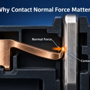
| Contact normal force | Mated conductive contact surfaces | Force pressing the electrical contact surfaces together |
| Crimp pull-out force | Wire-to-terminal crimp | Mechanical strength of the crimped joint |
These distinctions appear in manufacturer test documentation. For example, Molex’s 6.5 mm pitch receptacle test summary lists terminal insertion, terminal/housing retention, connector insertion and withdrawal, and retainer insertion as separate test items. Its values and test speeds apply to that product; they are not general limits for other connectors. Molex test summary, sections 3.2.1–3.2.5
This article concerns terminal-to-housing assembly. Pressing a compliant pin into a plated PCB hole is a different joint and needs its own installation and acceptance criteria.
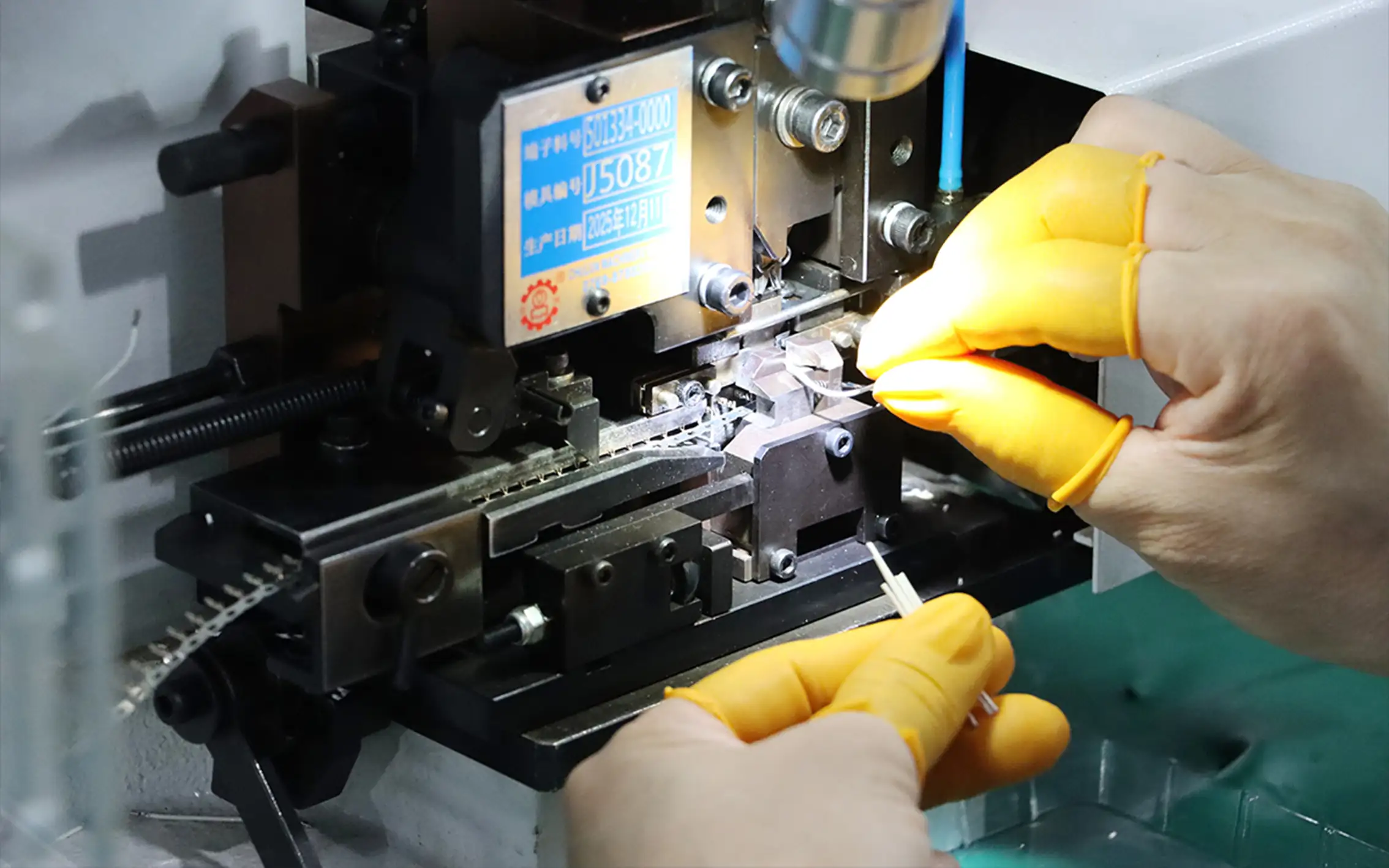
Housing Cavity Geometry Determines the Insertion Path
The terminal must pass through the entrance, follow the cavity, and reach the position defined by the connector design. Lead-in geometry and orientation features help guide that movement. TE’s ergonomic connection guide identifies cavity lead-ins, polarization, and protection against contact stubbing as practical assembly considerations. TE Connectivity ergonomic connections guide
For a manufacturing review, assess the terminal and housing together. Useful questions include:
- Does the cavity entrance guide the terminal before a fragile feature can strike an edge?
- Do formed terminal dimensions, burrs, or deformation interfere with the available passage?
- Can molding variation, flash, or cavity distortion restrict the path?
- Does the fixture locate the housing from a stable reference?
- Is there enough controlled travel to reach the seating position without damaging the assembly?
These are investigation points, not a diagnosis from the force value. A high reading at one cavity may justify checking that cavity and its alignment first. A shift across many cavities may justify checking the component lot, fixture setup, or process settings.
Stamping and molding inspection results are most useful when they can be related back to the affected cavity and assembly operation.
The Locking Feature Must Engage Without Damage
Some terminals have a metal lance that deflects during insertion and engages a housing feature. Other designs use a locking feature molded into the housing. The retention mechanism determines which dimensions, deflections, and seating features matter.
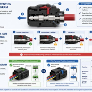
Molex distinguishes terminal-level retention from the mechanisms holding the two connector halves together. Its retention guide also describes how terminal position assurance, or TPA, can supplement terminal retention, with implementations varying by design. Molex connector contact retention guide
An assembly review should therefore start with the actual section drawing. Identify the feature that carries the withdrawal load, the surface it engages, and the movement needed to reach engagement.
Do not assume that every terminal should produce the same force peak or an audible click. Likewise, an unusually easy insertion needs investigation if the validated process normally shows resistance at a particular position. The target is a repeatable, damage-free assembly within the approved limits.
Misalignment Can Turn an Assembly Step into a Failure
Correct orientation is product-specific. Molex’s Micro-Fit application specification, for example, illustrates different terminal orientations for its standard and TPA housing versions and requires terminals to be fully seated and locked. Similar-looking cavities are not enough to establish the correct insertion direction. Molex Micro-Fit application specification, pages 4–5
Consider an illustrative assembly problem: a terminal enters at a slight angle and meets an internal edge. The operator or machine continues pushing. The measured force rises, but the terminal does not advance as intended.
That event calls for inspection of alignment and possible damage. Increasing the force limit would only remove the alarm; it would not explain the interference.
For manual assembly, establish a clear orientation reference and use the specified insertion tool where required. For automated insertion, review the gripper location, terminal presentation, cavity reference, and travel direction. Any recovery or reinsertion procedure should be approved for that terminal system.
Terminal Back-Out: Why Initial Continuity Is Insufficient
Terminal back-out is rearward displacement of a terminal from its intended position in the housing. Inadequate retention can contribute to intermittent electrical faults under mechanical stress. Molex connector contact retention guide
A continuity test answers an electrical question under the conditions present during that test. It does not directly measure engagement of a locking feature. The engineering implication is that an electrical pass should not replace the mechanical seating checks specified for the assembly.
Downstream handling also matters. Molex’s Micro-Fit application guidance warns against excessive wire tension and concentrated loading on individual wires because these loads can pull a terminal out. Molex Micro-Fit application specification, page 10
When investigating a back-out complaint, ask when the terminal position first changed: during insertion, secondary-lock closure, connector mating, harness routing, or later handling. That sequence helps distinguish an installation problem from a subsequent loading problem.
Secondary Locks Need Their Own Verification
A secondary lock can reinforce terminal retention or help confirm seating, depending on its design. Follow the specified assembly sequence and final-position criteria. Terminal position assurance (TPA) concerns individual terminals; connector position assurance (CPA) concerns the mated connector halves. Molex connector contact retention guide
Treat secondary-lock closure as a separate control point. Define the correct starting position, actuation direction, permitted force, and final condition from the product instructions.
If the lock does not close normally, inspect the assembly before applying more force. Possible investigation points include terminal depth, component compatibility, obstruction, and lock damage. A closed external feature should be interpreted according to the design’s verified detection capability, rather than assumed to reveal every hidden defect.
Automated Insertion: Measure the Process and the Result
Automation can combine terminal presentation, housing location, controlled movement, and checks after insertion. Komax’s Omega documentation provides a concrete example: optical measurement supports positioning, force sensors monitor insertion, and a pull-off check evaluates terminal locking. These are equipment features described by Komax, not a statement about equipment installed at FPIC. Komax Omega 740/745/750/755 brochure, version 3, February 2023
For a new assembly process, define the required evidence before choosing the sensor arrangement. Recommended records include the part and cavity identity, recipe revision, insertion result, final-position result, and the specified locking check. Where force traces are captured, retain enough context to compare like-for-like operations.
Changing a terminal, seal, fixture, insertion speed, or housing version may change the process signature. Review and revalidate affected monitoring limits instead of copying an existing recipe without checking its applicability.
Why Terminal Insertion Force Monitoring Needs Displacement
A single peak records how much force occurred, but not where it occurred. Force measured against displacement adds information about the sequence of an assembly operation. Kistler describes combined force and displacement measurement as a basis for monitoring joining processes. Kistler joining and testing for assembly processes
For terminal insertion, the following is a suggested troubleshooting framework. The observations are reasons to inspect; none uniquely identifies a defect.
| Observation against a validated reference | Investigation priorities | Follow-up evidence |
|---|---|---|
| Force rises unusually early | Terminal angle, cavity entrance, fixture position | Alignment check and inspection of contact marks |
| Resistance remains unusually high | Component dimensions, obstruction, seal condition where applicable | Dimensional inspection and controlled assembly comparison |
| Expected trace feature is absent | Locking geometry, component identity, measurement setup | Seating inspection and specified retention check |
| Travel ends before the approved position | Incomplete insertion, reference error, tool limitation | Independent final-position measurement |
| Insertion appears acceptable but locking check fails | Retention feature or seating problem | Detailed terminal and housing inspection |
The sensor measures force through its particular load path. Depending on the setup, seal drag, fixture friction, wire bending, and machine compliance can affect the result. Define where displacement is measured and how it relates to actual terminal movement.
Validate the monitoring method with representative acceptable assemblies and controlled defect samples. Check whether it separates the relevant conditions reliably. A trace that looks different is useful evidence; a trace that looks normal is not a universal guarantee.
Final Retention Verification Completes the Assembly Check
Installation resistance and resistance to removal are different properties. A manufacturing control plan should specify how both are addressed and distinguish routine production checks from qualification testing.
Use the following as a review checklist:
- Confirm compatible components. Verify the terminal, housing, wire, seal, and secondary-lock versions against released documentation.
- Define insertion conditions. Record orientation, fixture references, speed, travel, and applicable force limits.
- Check final position. Establish an accessible seating reference and a suitable measurement or inspection method.
- Verify locking as specified. Use the approved nondestructive back-pull or tug check only where required, with its defined load and sequence.
- Confirm the secondary lock. Check its final condition where the connector includes one.
- Complete electrical and qualification checks. Apply the relevant production tests and separately defined retention and environmental validation plan.
A routine locking check must not be confused with a destructive pull-to-failure test. Define sample selection, load direction, speed, conditioning, lock state, and acceptance criteria for the applicable test. Do not transfer a minimum retention value directly into an every-part production proof load without validation.
For PCB connectors, identify the assembly being evaluated. Contact insertion into a molded header, retention of that contact in the header, and installation of the header onto the PCB may require different methods.
Connecting Terminal Design with Manufacturing at FPIC
At FPIC, terminal and housing development can be reviewed alongside tooling, plastic injection, metal processing, assembly, and laboratory validation. Published capabilities include dimensional inspection, insertion and withdrawal force testing, and assembly quality checks. The relevant test fixture and control plan still need to be defined for each product. FPIC R&D and Quality Assurance
For an assembly review, share the terminal and housing drawings, component versions, assembly sequence, and any force or back-out observations. These details provide a useful starting point for evaluating the fit between the design and the process.
Frequently Asked Questions
What is terminal insertion force?
Terminal insertion force is the force needed to install a terminal into its connector housing. It characterizes the installation operation; it does not directly establish the terminal’s retention strength after assembly.
Is lower terminal insertion force always better?
No. Lower force may make installation easier, but acceptance depends on the approved product and process requirements. An unexpected reduction should be investigated alongside terminal position and locking performance.
What causes terminal back-out in a connector?
Potential causes include incomplete seating, damaged or ineffective retention features, incorrect components, and excessive loading after assembly. Inspect when and where displacement occurred before assigning a root cause.
Can insertion force monitoring replace retention testing?
It should not be assumed to do so. Monitoring evaluates the insertion event, while a specified locking or retention check evaluates a different aspect of the assembly. Any proposed substitution needs application-specific validation and approval.
What is an acceptable terminal insertion force?
Use the limit and test method specified for the terminal–housing combination. There is no single value appropriate for all automotive, PCB, and industrial connectors. Also confirm the assembly condition, speed, direction, and lock configuration.
How does terminal insertion differ from contact wipe and normal force?
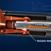
Terminal insertion concerns installing the terminal in its housing. Contact wipe describes sliding at the conductive mating interface; contact normal force describes pressure between those conductive surfaces. They belong to related but separate design and verification tasks.
Resources
- Molex: 6.5 mm pitch receptacle test summary — Separate insertion, retention, and retainer test items.
- TE Connectivity: Ergonomic Connections Product Solution Guide — Assembly force, orientation, lead-ins, and stubbing prevention.
- Molex: Connector Contact Retention Guide — Terminal retention, TPA, and CPA distinctions.
- Molex: Micro-Fit application specification — Product-specific orientation, seating, and wire-routing instructions.
- Komax: Omega harness assembly brochure — Optical positioning, insertion monitoring, and locking checks.
- Kistler: Joining and testing for assembly processes — Force and displacement monitoring.


 FPIC
FPIC