Why Contact Normal Force Matters in Connectors
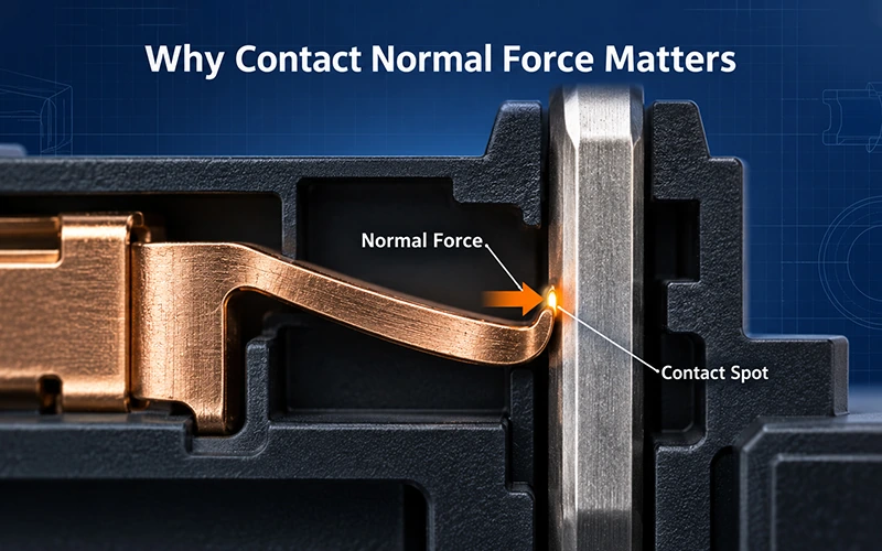
Contact normal force is the perpendicular load a spring contact applies to its mating surface. If that force is too low – or falls after heat, wear, or vibration – a connector can pass an initial continuity test yet develop unstable resistance later.
Short answer: A reliable separable contact needs enough normal force to create and preserve microscopic conductive contact spots. Too little force makes the interface more sensitive to surface films and movement. Excessive force increases mating effort, plating wear, and the risk of permanent deformation. The correct target is a controlled force window over the connector’s intended life.
That is why normal force should be treated as a lifetime design parameter, not just a value checked on a new sample.
What Is Contact Normal Force?
When a pin or blade enters a receptacle, the receptacle’s spring feature deflects. The elastic reaction presses the two conductive surfaces together. The component of that load acting perpendicular to the mating surface is the contact normal force.
The term is often confused with three other connector measurements:
| Measurement | What It Describes | Why It Matters |
|---|---|---|
| Contact normal force | Perpendicular load applied by the spring contact to the mating surface | Controls the stability of the separable electrical interface |
| Mating and unmating force | Axial force required to engage or separate the connector halves | Affects assembly, serviceability, ergonomics, and wear |
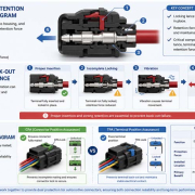
| Terminal retention force | Force required to pull a terminal from its housing cavity | Verifies the terminal lock, lance, or secondary retention system |
| Crimp pull-out force | Mechanical strength of the wire-to-terminal crimp | Verifies the permanent termination, not the mating interface |
A connector can meet terminal-retention and crimp requirements while still having inadequate spring force at the electrical contact point. It can also have acceptable normal force but excessive total mating force because seals, locks, alignment, friction, and multiple circuits add resistance during engagement.
How Contact Force Affects Contact Resistance
Metal surfaces may look smooth, but at microscopic scale they touch at small high points called asperities. Current therefore crosses the interface through a limited number of real contact spots rather than the full visible area.
Applying normal load deforms some asperities, increases effective contact area, and can help penetrate or displace oxide and contamination films. This reduces the constriction and film-related components of interface resistance. Research on electrical contact mechanics links constriction resistance to the mechanical stiffness and load of the interface, while also showing that surface films can strongly change the result.
It helps to separate three parts of a connector’s conductive path:
- Bulk resistance through the metal contact.
- Termination resistance at the crimp, solder joint, or press-fit section.
- Interface resistance where the separable contacts meet.
Normal force mainly influences the third part. Changing spring pressure does not repair a poor crimp, undersized conductor, damaged solder joint, or unsuitable base material.
More Force Is Not Always Better
At the low end, insufficient pressure can produce fewer stable contact spots and greater sensitivity to films, contamination, vibration, and tolerance variation. Raising the load generally reduces and stabilizes interface resistance, but the benefit does not continue without limit.
Excessive force can create other problems:
- High insertion and withdrawal loads, especially in multi-position connectors
- Faster wear of tin, gold, or other contact finishes
- Damage to the mating surface during repeated operation
- Permanent set if the spring exceeds its elastic design range
- Housing distortion, difficult assembly, or incomplete mating
The engineering objective is therefore not maximum force. It is sufficient retained force with acceptable mating effort, wear, temperature rise, and dimensional margin. The target must be defined for the specific contact geometry, material, plating system, mating counterpart, environment, and required service life.
Spring Geometry and Material Set the Force Window
Within its elastic range, a contact spring behaves approximately as force equals stiffness multiplied by deflection. That simple relationship explains why the male contact, female spring, housing, and manufacturing tolerances must be designed as one system.
Spring stiffness and working stress are influenced by:
- Beam length, width, thickness, and formed geometry
- Contact angle and the location of the contact point
- Bend radii and transitions that concentrate or distribute stress
- Deflection created by the minimum and maximum mating-contact dimensions
- Elastic modulus, yield strength, fatigue performance, and material temper
- Residual stress introduced during stamping and forming
Thickness is especially sensitive in many spring designs because a small dimensional change can cause a much larger change in stiffness. The exact relationship depends on the contact form, so designers should use calculation or simulation together with physical force-displacement measurements.
Material Selection Is a Trade-Off
Brass, phosphor bronze, and higher-performance copper alloys can all be appropriate contact materials in the right design. Selection should consider conductivity, yield strength, formability, fatigue resistance, corrosion behavior, cost, and stress-relaxation performance at the expected temperature.
A highly conductive alloy may help control bulk heating but may not retain spring stress as well as another alloy. A stronger material may allow useful deflection in a compact geometry, but strength alone does not prove long-term force retention. Material temper, grain direction, forming history, and operating temperature also matter.
Production Variation Changes Real Contact Force
The CAD model represents a nominal condition. Production parts contain normal variation from strip thickness, stamping dimensions, forming angles, tool wear, material properties, plating thickness, housing dimensions, and mating-pin size.
These variations form a tolerance stack. At one extreme, the contact may be too loose. At the other, it may be overstressed or difficult to mate. Critical spring dimensions therefore require production controls linked to the force and electrical requirements they influence.
Plating and lubrication also affect friction. They can change total mating force even when spring pressure stays similar, which is another reason not to infer normal force from connector insertion force alone.
Stress Relaxation at High Temperature
Stress relaxation is the gradual loss of stress in a spring held at a substantially constant deflection. In a connector, the contact may remain mated while its spring load slowly decreases. Higher temperature generally accelerates this process, and different copper alloys can retain force at very different rates.
The contact experiences both ambient heat and self-heating. For a current-carrying interface, local power dissipation follows:
P = I²R
If interface resistance rises, local heating can rise. Higher temperature can then accelerate force loss, oxidation, or other degradation mechanisms. This does not mean every connector enters thermal runaway, but it shows why electrical, thermal, and mechanical design cannot be separated.
Designers often allow for expected force loss by starting above the minimum end-of-life requirement. However, simply increasing initial force can raise mating effort and plating wear. A better approach balances spring geometry, alloy, temperature exposure, finish, and required life so that sufficient force remains after aging without creating excessive force when new.
Repeated Mating Changes the Interface
Mating creates a wiping action between the contact surfaces. Controlled wiping can help disrupt surface films and establish a conductive contact region. The same sliding action also creates friction and gradually wears the finish.
Normal force affects both effects. Too little pressure may not create a stable interface. Too much pressure can increase friction and remove plating faster. Once the finish is locally worn through, exposed underplate or base metal may behave differently in humidity, pollutants, or corrosive environments.
Cycle count alone is therefore incomplete. A durability plan should define the mating counterpart, engagement speed, alignment, lubrication condition, environmental exposure, and measurements taken before and after cycling. Contact resistance and force after the required number of operations are more informative than a visual statement that the connector still mates.
Vibration and Micro-Movement
A connector lock prevents the housings from separating, but it does not automatically stop microscopic motion at the contact spot. Vehicle vibration, equipment movement, cable loading, and differential thermal expansion can produce small relative displacements inside a fully mated connector.
This movement can damage surface films and generate wear debris. With susceptible finishes and environments, the debris can oxidize and increase resistance – a process commonly associated with fretting corrosion. The result may be a gradual resistance increase or intermittent discontinuity that does not appear during a static bench check.
Retained normal force and suitable spring stiffness help stabilize the interface, but they are only part of the solution. Contact geometry, finish, lubrication where permitted, housing support, locking, cable strain relief, and vibration spectrum must be considered together.
Why Initial Continuity Does Not Prove Long-Term Reliability
A continuity check confirms that an electrical path exists at the moment of measurement. New, clean contacts can pass even when the design has limited margin against force loss or environmental aging.
An initial test does not by itself reveal:
- How much normal force remains at the lowest material and dimensional condition
- Whether high-temperature exposure will relax the spring
- Whether the finish will survive the specified mating cycles
- Whether vibration will cause micro-motion or intermittent events
- Whether corrosion products will increase resistance
- Whether current-induced heating will remain acceptable
Low-level contact resistance testing provides a more sensitive view of the mated interface than a basic continuity check. It should still be combined with mechanical and environmental conditioning. IEC 60512-2-1 defines a millivolt-level method for measuring resistance across mated contacts, while other parts of the IEC 60512 series address temperature rise, vibration, mechanical operation, and corrosion exposure.
The applicable customer specification may instead reference USCAR, LV214, EIA-364, or another sector-specific standard. The correct sequence, severity, sample preparation, monitoring method, and acceptance limits must come from the product’s detail specification and application requirements.
A Practical Contact Validation Plan
Long-term performance is best evaluated as a sequence rather than a group of unrelated pass/fail checks.
| Validation Stage | What to Control or Measure | Engineering Question |
|---|---|---|
| Design input | Current, temperature, vibration, mating cycles, environment, mating counterpart | What conditions must the interface survive? |
| Material and dimensions | Alloy, temper, strip thickness, spring geometry, plating, housing and mating-contact tolerances | Does the full tolerance stack stay within the intended force window? |
| Baseline mechanics | Force-displacement behavior, mating/unmating force, gauge retention where applicable | Is the new contact mechanically correct without overstress? |
| Baseline electrical | Low-level contact resistance, voltage drop, temperature rise or current derating as required | Does the interface perform before conditioning? |
| Durability | Specified mating cycles followed by force, resistance, and surface review | Does wiping or wear change performance? |
| Thermal and climatic aging | High-temperature exposure, thermal cycling, humidity, or corrosive atmosphere as applicable | Does the spring retain force and does the finish protect the interface? |
| Dynamic testing | Vibration and shock, with discontinuity monitoring when required | Does the mated system remain stable under movement? |
| Final assessment | Repeat mechanical and electrical measurements; inspect contact surfaces | Is the design still within its acceptance limits after the full sequence? |
IEC 60512-9-1 addresses mechanical operational endurance, IEC 60512-6-4 covers sinusoidal vibration, and IEC 60512-11-7 provides a flowing mixed-gas method for evaluating low-concentration pollutant effects on contacts. These standards define test methods, not universal acceptance values for every connector.
Questions to Resolve During Design Review
Before approving a contact system, engineering and procurement teams should ask:
- What is the minimum required force after thermal aging and durability testing?
- What force occurs at the maximum mating-contact dimension?
- Could any tolerance condition exceed the material’s elastic limit?
- What ambient temperature, current, and local temperature rise are expected?
- Which plating system and thickness are specified at the contact zone?
- How many mating operations must the interface withstand?
- What vibration, shock, humidity, pollutant, or corrosive exposure applies?
- How will force and resistance be measured before and after conditioning?
- Which dimensions and material properties require production monitoring?
These questions turn a vague request for a “reliable terminal” into measurable design and validation requirements.
How FPIC Supports Contact-System Development
For applicable automotive, PCB, wire-to-board, and precision-terminal projects, FPIC can coordinate terminal design review, tooling, stamping, molding, assembly, and project-specific verification. Available laboratory support includes contact-resistance, insertion-and-withdrawal-force, temperature-rise, vibration, and coating-thickness checks according to the agreed validation plan.
The acceptance criteria remain product- and application-specific. Customers should provide the terminal and housing drawings, mating-contact dimensions, material and plating requirements, current, temperature range, mating cycles, environmental conditions, target volume, and applicable standards for technical evaluation.
Conclusion
A contact system needs normal force to remain inside the required window after tolerances, heat, mating wear, and vibration have done their work. Initial continuity is a starting measurement; long-term confidence comes from coordinated spring design, materials, manufacturing control, and sequence-based validation.
To discuss a custom connector, terminal, or PCB interconnect project, contact FPIC at info@fpiconn.com.
Frequently Asked Questions
What is contact normal force in a connector?
Contact normal force is the perpendicular load that a spring contact applies to its mating pin, blade, or pad. It helps establish and maintain the microscopic conductive spots at the separable interface.
Does higher contact force always reduce resistance?
No. Increasing a low force can improve interface stability, but excessive force can raise mating effort, wear the plating, distort the housing, or permanently deform the spring. Designers need a validated operating window rather than the highest possible value.
Is contact normal force the same as insertion force?
No. Normal force acts at the contact surface, while insertion force is measured in the mating direction and also includes friction, contact angle, seals, alignment, locks, and the combined effect of multiple circuits.
How does high temperature affect terminal spring force?
High temperature can accelerate stress relaxation, causing a deflected spring contact to lose load over time. The rate depends on alloy, temper, geometry, stress level, temperature, and exposure duration.
Can a connector pass continuity testing and still fail later?
Yes. A clean new interface may pass continuity even if it has limited margin against thermal relaxation, plating wear, fretting, corrosion, or dimensional variation. Mechanical and environmental conditioning followed by resistance measurement provides stronger evidence.
Which tests help evaluate long-term contact reliability?
The validation plan may include force-displacement measurement, low-level contact resistance, temperature rise or derating, mating durability, thermal aging, temperature cycling, humidity or corrosion exposure, vibration, shock, and post-test surface inspection. The applicable standard and limits depend on the product and application.
Resources
- B. N. J. Persson, “On the Electric Contact Resistance,” Tribology Letters, 2022.
- Materion, “What Is Stress Relaxation of Materials?” 2024.
- Materion, “How Can Connector Insertion Force Be Reduced?” 2024.
- Materion, “What Makes a Good Spring Material?” 2024.
- IEC 60512-2-1:2002, Contact Resistance – Millivolt Level Method.
- IEC 60512-5-1:2002, Temperature Rise.
- IEC 60512-6-4:2002, Vibration (Sinusoidal).
- IEC 60512-9-1:2010, Mechanical Operation.
- IEC 60512-11-7:2003, Flowing Mixed Gas Corrosion Test.
- SAE International, USCAR2-9, Performance Specification for Automotive Electrical Connector Systems, 2024.