Why Contact Resistance Drift Matters in Automotive Connectors Design
In automotive electrical systems, Automotive connectors performance is often evaluated based on initial specifications—contact resistance, current capacity, and mechanical retention. However, long-term reliability is not determined at time zero. It is shaped by how these parameters evolve over time.
One of the most critical yet often underestimated factors is contact resistance drift.
Contact resistance drift refers to the gradual increase or fluctuation of resistance at the electrical interface between mating terminals. While the change may be small in absolute terms, its impact can be significant—especially in high-current, high-voltage, and signal-sensitive automotive systems.
Understanding Contact Resistance at the Interface Level
Electrical contacts are not perfectly smooth surfaces. Even highly polished terminals only touch at microscopic asperities.
This means:
- the real contact area is much smaller than the apparent area
- current flows through discrete micro-contact points
- resistance is highly sensitive to surface condition and contact force
Any change in these micro-contact conditions—such as oxidation, wear, or reduced contact pressure—can increase resistance.
Over time, these small changes accumulate, resulting in measurable resistance drift.
Why Contact Resistance Drift Matters
Heat Generation and Thermal Runaway Risk
In power circuits, resistance increase leads directly to higher heat generation (I²R losses). This can create a feedback loop:
- higher resistance → more heat
- more heat → faster material degradation
- degradation → further resistance increase
In severe cases, this can lead to localized overheating or even thermal runaway in high-power systems.
Voltage Drop and Efficiency Loss
In EV and power distribution systems, even a small resistance increase can result in:
- measurable voltage drop
- reduced energy efficiency
- performance degradation in motors or inverters
As system voltages rise, maintaining stable connections becomes even more critical.
Signal Integrity Degradation
For low-current signal circuits, resistance drift affects:
- signal amplitude
- noise margin
- communication stability
This is particularly important in CAN, LIN, and automotive Ethernet systems, where stable electrical characteristics are required for reliable data transmission.
Root Causes of Contact Resistance Drift
Contact resistance drift rarely has a single cause. It is typically the result of multiple interacting factors.
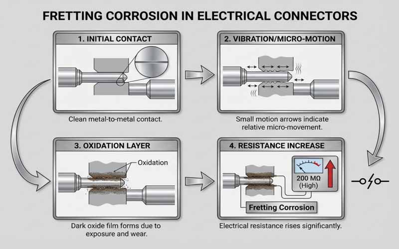
Fretting Corrosion
Micro-motion between contact surfaces caused by vibration leads to:
- wear of protective plating
- formation of oxide debris
- increased contact resistance
This is one of the most common failure mechanisms in automotive connectors.
Oxidation and Environmental Exposure
Exposure to oxygen, humidity, and contaminants can form insulating layers on contact surfaces.
Key risk factors include:
- unsealed connectors
- harsh environmental conditions
- long service life
Loss of Contact Force
Contact force is critical for maintaining a stable electrical interface. Over time, it can decrease due to:
- material creep
- thermal cycling
- stress relaxation
Reduced force leads to smaller effective contact area and higher resistance.
Plating Degradation
Surface plating (tin, silver, or gold) is designed to protect against corrosion and ensure conductivity. However:
- repeated mating cycles can wear plating
- vibration can accelerate degradation
- base materials may oxidize once exposed

Real-World Conditions Accelerate Drift
Laboratory testing often evaluates connectors under controlled conditions. However, real automotive environments introduce combined stresses:
- continuous vibration from road conditions
- wide temperature fluctuations
- moisture, dust, and chemicals
- harness movement and mechanical strain
These factors do not act independently—they interact and accelerate degradation mechanisms.
As a result, contact resistance drift in real applications is often faster and more complex than predicted by isolated testing.
High-Risk Automotive Applications
High-Current Systems
- battery connections
- inverter interfaces
- power distribution units
These systems are sensitive to heat and efficiency loss.
High-Speed Data Systems
- ADAS sensors
- communication networks
- control modules
These systems are sensitive to signal degradation.
Safety-Critical Systems
- braking systems
- airbag systems
- vehicle control electronics
In these applications, even intermittent resistance variation can lead to unacceptable risk.
Strategies to Control Contact Resistance Drift
Optimize Contact Design
- maintain stable contact force over time
- design for vibration resistance
- ensure sufficient contact area
Select Appropriate Materials and Plating
- use corrosion-resistant materials
- match plating type to application (tin vs gold)
- consider mating cycle requirements
Improve Sealing and Environmental Protection
- use sealed connectors in harsh environments
- minimize exposure to moisture and contaminants
Control Harness Movement
- reduce micro-motion through proper routing
- add strain relief and fixation points
- avoid unnecessary stress at connectors
Validate Under Realistic Conditions
Testing should include:
- vibration + temperature combined testing
- long-term aging simulation
- real installation conditions
How FPIC Supports Stable Electrical Performance
Ensuring stable contact resistance requires coordination across connector design, cable assembly, and manufacturing processes.
FPIC supports customers with:
- connector and cable integration design
- controlled crimping and termination processes
- application-based validation strategies
- manufacturing consistency for long-term stability
By addressing both design and process variables, resistance drift can be effectively minimized.
Final Thoughts
Contact resistance drift is a slow but critical failure mechanism in automotive connectors. It does not cause immediate failure—but it gradually reduces system reliability until problems emerge.
As vehicles become more electrified and data-driven, the tolerance for electrical instability continues to decrease.
A robust connector design strategy must go beyond initial specifications and focus on long-term performance under real-world conditions.
FAQ
What is contact resistance drift?
It is the gradual increase or variation of resistance at an electrical contact interface over time.
Why is it important in automotive systems?
Because it affects heat generation, voltage stability, and signal integrity—critical factors in vehicle performance and safety.
What is the most common cause?
Fretting corrosion caused by vibration-induced micro-motion is one of the primary causes.
Can it be completely eliminated?
No, but it can be significantly reduced through design, material selection, and validation.
How is it tested?
Through contact resistance measurement under environmental stress conditions such as vibration and thermal cycling.
Improve Connector Reliability in Real Conditions
If your application involves high-current, high-voltage, or signal-critical systems, controlling contact resistance drift is essential.
FPIC provides custom connector and cable assembly solutions with a focus on long-term electrical stability and real-world reliability.
Contact us to discuss your project requirements.
Resources
- USCAR-2 – Performance Specification for Automotive Electrical Connector Systems: includes durability and contact resistance testing methods for automotive connectors.
- TE Connectivity – Contact Physics in Electrical Connectors: explains how micro-contact behavior influences resistance stability.
- Molex – Fretting Corrosion in Connector Systems: details the mechanisms behind resistance increase under vibration.
- Amphenol – Connector Design Fundamentals: covers materials, plating, and environmental considerations affecting electrical performance.
- IEC 60512 – Electrical Connector Testing: defines standardized methods for measuring contact resistance and durability.


 FPIC
FPIC 

