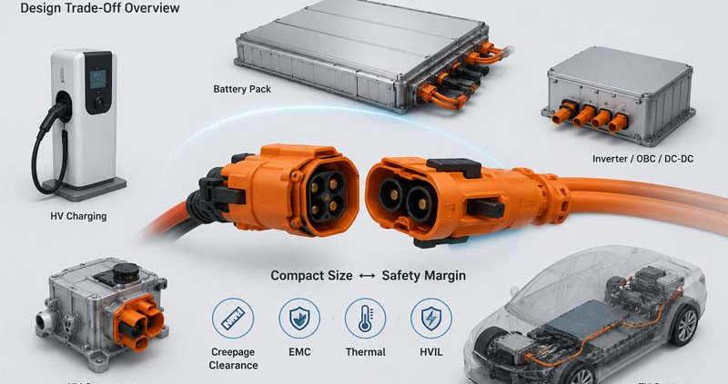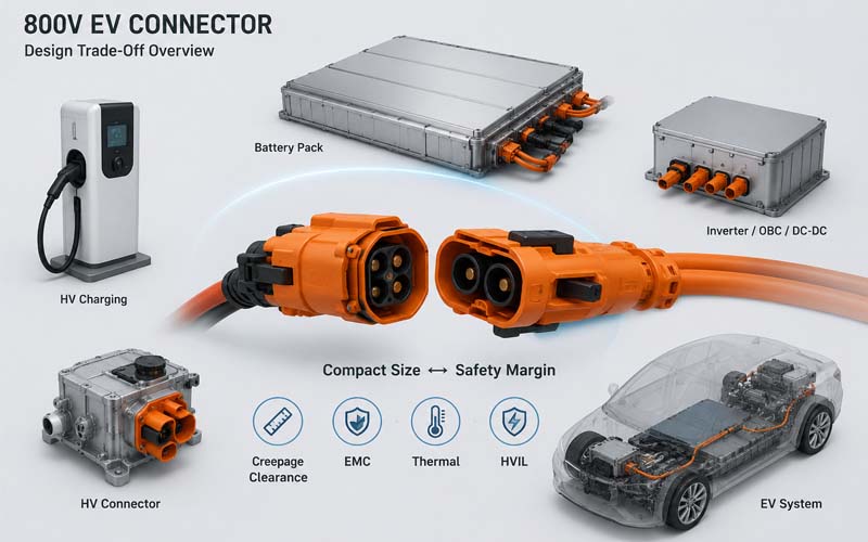
800V EV CONNECTOR Design Trade-Off Overview

The transition from 400V to 800V vehicle architectures is reshaping the design of high-voltage connector.

Automakers are adopting 800V systems to support:

  • faster charging
  • higher power density
  • improved drivetrain efficiency
  • reduced cable weight

However, increasing system voltage creates new engineering challenges.

Connector designers must balance two competing objectives:

  • minimizing size and weight
  • maintaining adequate electrical safety margins

This trade-off affects nearly every aspect of connector development, from insulation design to thermal performance and EMC behavior.

800V EV CONNECTOR Design Trade-Off Overview


Why 800V Systems Change Connector Design

At first glance, an 800V connector may appear similar to a 400V connector.

In reality, the higher operating voltage increases the importance of:

  • insulation coordination
  • creepage distance
  • clearance distance
  • dielectric performance
  • contamination resistance
  • transient voltage withstand capability

The design window becomes significantly smaller.


The Industry Push Toward Compact Packaging

Vehicle manufacturers constantly seek:

  • lighter vehicles
  • smaller power electronics
  • tighter battery packaging
  • reduced installation space

As a result, connectors are expected to deliver:

  • higher voltage
  • higher current
  • smaller size

These requirements often conflict with each other.


The Creepage and Clearance Challenge

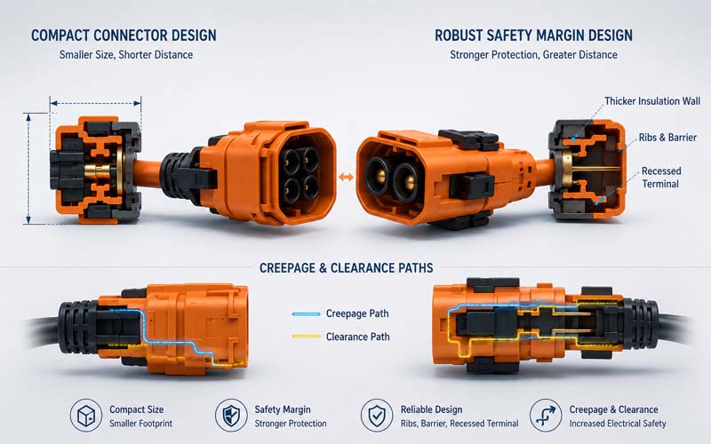
One of the most significant design constraints is maintaining sufficient electrical spacing.

Higher voltages generally require:

  • larger clearance distances
  • longer creepage paths
  • improved insulation structures

However, increasing spacing also increases connector size.

Designers often use:

  • insulating ribs
  • internal barriers
  • recessed terminals
  • optimized conductor geometry

to maximize electrical separation within limited packaging volume.

Compact Design vs Electrical Safety Comparison


Safety Margin vs Minimum Compliance

Meeting a standard requirement is not always enough.

A connector may technically comply with a specified spacing requirement while having limited margin for:

  • manufacturing tolerances
  • contamination
  • aging
  • vibration
  • environmental exposure

Experienced engineers typically design beyond minimum values to improve robustness.


Thermal Performance Trade-Offs

Higher voltage systems often support higher power levels.

To reduce size, designers may attempt to:

  • reduce terminal dimensions
  • decrease connector footprint
  • increase current density

These changes can increase:

  • contact temperature
  • thermal stress
  • material aging

Thermal validation becomes increasingly important in compact 800V designs.


Shielding and EMC Constraints

Modern 800V systems contain:

  • traction inverters
  • onboard chargers
  • DC/DC converters
  • high-speed communication networks

Effective shielding often requires:

  • metal shells
  • conductive backshells
  • 360° shield termination

These features consume valuable packaging space.

Reducing connector size may compromise EMC performance if shielding design is not carefully optimized.


HVIL Integration Challenges

Many 800V connectors incorporate HVIL (High Voltage Interlock Loop) functionality.

Additional HVIL contacts require:

  • dedicated space
  • mechanical protection
  • routing paths
  • insulation separation

Compact packaging increases the complexity of integrating these safety functions.


Mechanical Durability Considerations

Smaller connectors are often more sensitive to:

  • tolerance variation
  • vibration
  • mating misalignment
  • terminal movement

Maintaining long-term durability while reducing size requires careful mechanical design.


Environmental Sealing Trade-Offs

800V connectors frequently require:

  • IP67 protection
  • IP68 protection
  • chemical resistance
  • pressure resistance

Adding robust sealing features increases:

  • connector volume
  • mating force
  • manufacturing complexity

Yet inadequate sealing can significantly reduce safety margins.


Material Selection Becomes More Important

Material choice directly influences:

  • dielectric strength
  • CTI performance
  • thermal stability
  • mechanical durability

Higher-performance materials may allow more compact designs but often increase cost.


Manufacturing Tolerance Considerations

A design that appears acceptable in CAD may become risky in production.

Engineers must account for:

  • molding variation
  • terminal positioning tolerance
  • assembly variation
  • wear over product life

Reduced safety margins leave less room for manufacturing variation.


Validation Requirements for 800V Connectors

Because design margins are tighter, validation becomes more critical.

Typical tests include:

  • HiPot testing
  • insulation resistance testing
  • thermal cycling
  • vibration testing
  • humidity exposure
  • salt spray
  • EMC validation
  • HVIL functional testing

Validation should simulate real operating conditions whenever possible.


Common Design Mistakes

Optimizing Only for Size

Electrical safety margins may become insufficient.

Ignoring Long-Term Aging

Material degradation can reduce insulation performance.

Underestimating EMC Requirements

Shielding limitations often appear late in development.

Relying Solely on Standard Minimums

Minimum compliance does not guarantee robustness.

Reducing Validation Scope

Aggressive packaging requires more testing, not less.


The Best Approach: Balanced Engineering

Successful 800V connector design is not about achieving the smallest possible package.

It is about balancing:

  • electrical safety
  • thermal performance
  • EMC performance
  • manufacturability
  • reliability
  • serviceability

The most reliable connectors typically incorporate appropriate engineering margin rather than pursuing extreme miniaturization.


How FPIC Supports 800V Connector Development

FPIC develops high-voltage connectors and cable assemblies for EV, ESS, and industrial electrification applications.

Our engineering support includes:

  • 800V connector architecture review
  • creepage and clearance optimization
  • HVIL integration
  • shielding design
  • thermal validation
  • prototype development
  • production manufacturing support

We help customers balance compact packaging with long-term reliability and safety.


Final Thoughts

The move to 800V architectures creates significant opportunities for vehicle performance and charging efficiency.

However, higher voltage leaves less room for design mistakes.

Engineers must carefully balance:

  • size
  • weight
  • insulation performance
  • thermal behavior
  • EMC requirements
  • durability

In high-voltage connector design, safety margin is not wasted space—it is often the foundation of long-term reliability.


FAQ

Why are 800V connectors more challenging than 400V connectors?

Higher voltage increases insulation and safety requirements while packaging space continues to shrink.

Can connector size always be reduced?

Not without affecting safety margin, thermal performance, or EMC behavior.

Why are creepage and clearance more critical in 800V systems?

Higher voltage increases the risk of arcing and surface tracking.

Does compact packaging affect EMC?

Yes. Reduced space can limit shielding effectiveness and grounding paths.

Should engineers design beyond minimum standard requirements?

In many applications, additional safety margin improves long-term reliability.


Developing an 800V EV or ESS Platform?

FPIC provides custom high-voltage connectors and cable assemblies designed for 800V architectures, combining compact packaging, robust insulation design, and validated reliability.

Contact us to discuss your high-voltage interconnect requirements.


Resources

  1. ISO 6469 – Electrically Propelled Vehicle Safety Requirements
    Safety requirements for high-voltage EV systems.
  2. IEC 60664-1 – Insulation Coordination for Low-Voltage Systems
    Fundamental guidance on creepage and clearance.
  3. LV214 / LV215 High-Voltage Automotive Connector Standards
    Automotive connector validation and design requirements.
  4. USCAR-2 Automotive Connector Performance Specification
    Connector reliability and environmental test requirements.
  5. TE Connectivity – High Voltage EV Connectivity Solutions
    Industry guidance on EV high-voltage interconnect design.
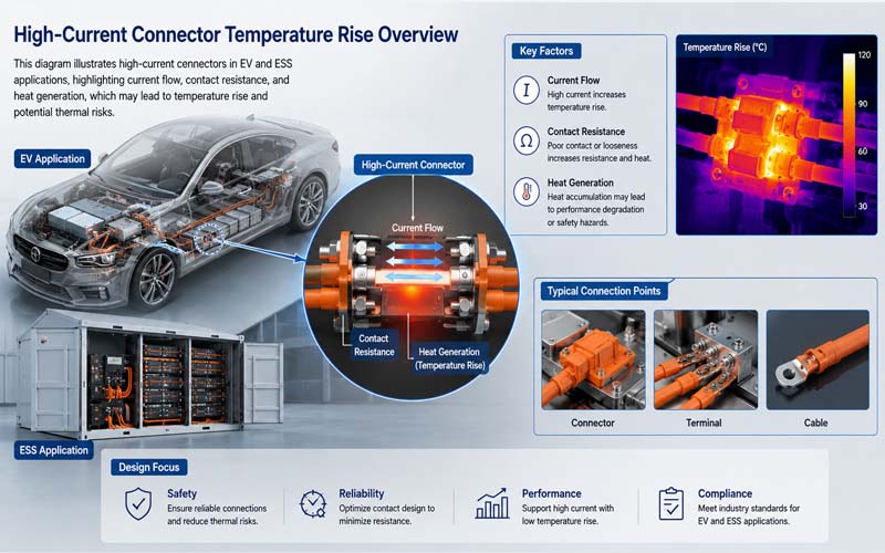
High-Current Connector Temperature Rise Overview

As electric vehicles (EVs), energy storage systems (ESS), and industrial electrification platforms continue increasing in power density, high-current connectors thermal performance has become a major engineering concern.

High-current connectors must safely carry large amounts of current for extended periods without excessive heating.

Even small increases in contact resistance can generate significant heat under high current conditions.

Temperature rise testing is therefore one of the most important validation methods for high-current connectors and cable assemblies.

This article explains why temperature rise testing matters, how test setups are designed, and the key failure risks engineers should monitor.

High-Current Connector Temperature Rise Overview.


Why Temperature Rise Testing Is Critical

A connector may pass continuity and dielectric tests while still suffering from poor thermal performance.

Excessive temperature rise can lead to:

  • insulation degradation
  • contact oxidation
  • reduced spring force
  • thermal runaway
  • voltage drop
  • accelerated aging
  • connector melting

Thermal issues are especially important in:

  • EV battery systems
  • inverters
  • OBC interfaces
  • DC fast charging
  • ESS battery cabinets

Basic Principle of Temperature Rise Testing

The test measures how much the connector temperature increases above ambient while carrying current.

The general process includes:

1.Apply specified current

2.Stabilize thermal conditions

3.Measure conductor and terminal temperatures

4.Compare temperature rise against acceptance criteria

The test evaluates the combined effect of:

  • contact resistance
  • conductor size
  • terminal design
  • plating quality
  • cooling conditions

What Causes Temperature Rise?

Heat generation mainly comes from electrical resistance.

The power loss relationship is approximately:

P = I²R

This means:

  • doubling current increases heat dramatically
  • small resistance increases can create large thermal effects

Critical resistance sources include:

  • contact interface resistance
  • crimp resistance
  • conductor resistance
  • degraded plating surfaces

Typical Test Setup

A temperature rise test setup generally includes:

  • programmable current source
  • calibrated thermocouples
  • data acquisition system
  • test fixture
  • controlled ambient environment

The connector is assembled using production-intent components and cable lengths.


Thermocouple Placement

Common measurement points include:

  • contact interface area
  • terminal crimp area
  • cable conductor near the connector
  • housing surface

Proper sensor attachment is critical for accurate results.


Steady-State Testing

Most tests continue until thermal stabilization occurs.

Steady state is typically defined as:

temperature change below a specified threshold over time

Depending on current level and connector mass, stabilization may require several hours.


Continuous Current vs Peak Current

Validation often includes both:

Continuous Current Testing

Evaluates long-term thermal capability.

Peak or Overload Testing

Assesses short-duration thermal stress.

Real applications may experience both conditions.


Important Environmental Factors

Temperature rise depends heavily on installation conditions.

Factors include:

  • ambient temperature
  • airflow
  • cable bundling
  • enclosure confinement
  • mounting orientation

Catalog ratings may not represent actual system conditions.


Common Failure Risks

High Contact Resistance

Poor contact interfaces create localized heating.

Inadequate Crimp Quality

Poor crimps increase resistance and heat generation.

Reduced Contact Force

Thermal cycling may weaken terminal spring force.

Poor Shield Grounding

In shielded connectors, grounding paths may also heat.

Insufficient Cooling

Compact packaging can trap heat.


Thermal Aging Effects

Long-term exposure to elevated temperature may cause:

  • oxidation
  • plastic deformation
  • plating degradation
  • insulation hardening
  • creep relaxation

Temperature rise testing is often combined with aging cycles.


Acceptance Criteria

Acceptance limits depend on:

  • connector material
  • insulation class
  • application standard
  • OEM requirements

Many standards specify maximum allowable temperature rise above ambient.


Relevant Standards

Common references include:

  • USCAR-2
  • LV214
  • IEC 60512
  • UL connector standards
  • OEM-specific validation requirements

Correlation with Other Tests

Temperature rise testing should be combined with:

  • contact resistance testing
  • thermal cycling
  • vibration testing
  • humidity exposure
  • mechanical durability testing

Many connector failures occur only after combined stress exposure.


Typical Applications

Temperature rise testing is essential for:

  • battery pack connectors
  • charging connectors
  • inverter interfaces
  • busbar connections
  • ESS power connectors
  • industrial high-current systems

How FPIC Supports Thermal Validation

FPIC provides high-current connector and cable assembly solutions with:

  • thermal performance evaluation
  • crimp resistance control
  • contact resistance verification
  • current cycling validation
  • customized test support
  • EV and ESS application engineering

We help customers optimize connector reliability under real operating conditions.


Final Thoughts

Temperature rise testing is one of the most important validation methods for high-current connectors.

A successful design depends on:

  • low and stable resistance
  • robust contact systems
  • controlled crimp quality
  • realistic installation conditions
  • comprehensive validation

As power density increases in EV and energy systems, thermal validation becomes increasingly critical to long-term reliability and safety.


FAQ

Why is temperature rise testing important?

It verifies whether a connector can safely carry current without overheating.

What mainly causes connector heating?

Electrical resistance at contacts, crimps, and conductors.

Does ambient temperature affect results?

Yes. Installation environment strongly influences thermal performance.

Can a connector pass electrical tests but fail thermally?

Yes. Low-level electrical tests may not reveal thermal weaknesses.

Why is steady-state testing necessary?

Because some thermal failures appear only after long stabilization periods.


Need Reliable High-Current Connector Solutions?

FPIC supports EV, ESS, and industrial projects with custom high-current connectors and cable assemblies validated for thermal performance and long-term reliability.

Contact us to discuss your application requirements.

Resources

  1. USCAR-2 – Automotive Connector Performance Specification
    Defines connector environmental and thermal validation requirements.
  2. IEC 60512 – Connector Test Methods
    International connector electrical and mechanical test procedures.
  3. LV214 Automotive Connector Validation Standard
    Automotive connector qualification requirements.
  4. TE Connectivity – High Current Connector Thermal Design
    Thermal considerations for high-power connectors.
  5. Molex – Power Connector Thermal Performance Guide
    Connector current carrying and temperature rise guidance.
High-Voltage Connector Supplier Qualification Checklist

In EV, energy storage, and industrial electrification projects, high-voltage connector are safety-critical components.

A connector failure can lead to:

  • vehicle shutdown
  • thermal damage
  • EMC issues
  • field recalls
  • safety risks
  • costly warranty claims

For OEM buyers, supplier selection is therefore not only a purchasing decision—it is a long-term quality and risk management decision.

Yet many sourcing evaluations still focus too heavily on price and catalog specifications.

This article explains the key technical, manufacturing, and quality factors OEM buyers should review before approving a high-voltage connector supplier.

High-Voltage Connector Supplier Qualification Checklist


Why Supplier Evaluation Matters

A high-voltage connector supplier becomes part of the OEM’s safety chain.

The supplier’s capabilities directly affect:

  • electrical reliability
  • production consistency
  • validation performance
  • traceability
  • launch timing
  • long-term field reliability

Even well-designed connectors can fail if manufacturing processes are unstable.


1.Review High-Voltage Application Experience

Not all connector manufacturers have genuine high-voltage expertise.

OEM buyers should confirm experience in:

  • EV battery systems
  • onboard chargers
  • inverters
  • ESS battery systems
  • industrial power electronics

High-voltage applications require different design and validation approaches compared with low-voltage connectors.


2.Verify Compliance with Automotive Quality Systems

A qualified supplier should operate under robust quality management systems such as:

  • IATF 16949
  • ISO 9001
  • ISO 14001

OEMs should verify:

  • certification status
  • audit performance
  • process discipline
  • corrective action systems

3.Evaluate Validation Capability

Suppliers should demonstrate the ability to perform or support:

  • temperature rise testing
  • contact resistance testing
  • vibration testing
  • thermal cycling
  • salt spray
  • sealing validation
  • HiPot testing
  • insulation resistance testing
  • HVIL functional validation
  • EMC-related validation

Validation capability is especially important for custom connector programs.


4.Assess Engineering Support

Strong engineering support often determines project success.

OEM buyers should evaluate whether the supplier can assist with:

  • connector selection
  • creepage and clearance review
  • shielding strategy
  • HVIL integration
  • cable routing
  • DFM (Design for Manufacturability)
  • tolerance analysis

Engineering responsiveness during development is critical.


5.Review Manufacturing Process Control

Manufacturing consistency is essential for high-voltage reliability.

Key areas to review include:

  • crimp process control
  • automated inspection
  • pull force testing
  • torque verification
  • traceability systems
  • SPC implementation
  • preventive maintenance

Process discipline often matters more than equipment appearance.


6.Inspect Traceability Systems

OEMs increasingly require full traceability.

Suppliers should be able to track:

  • raw materials
  • terminals
  • housings
  • plating lots
  • production dates
  • operators
  • inspection records

Fast containment capability reduces recall risk.


7.Check Shielding and EMC Expertise

Modern EV systems require strong EMC performance.

Suppliers should understand:

  • 360° shield termination
  • transfer impedance
  • grounding strategy
  • shielding continuity
  • EMC validation requirements

This is particularly important for OBC and inverter applications.


8.Evaluate Tooling and Prototype Capability

A capable supplier should support:

  • rapid prototypes
  • low-volume pilot builds
  • validation samples
  • production tooling development
  • PPAP support

Prototype responsiveness often impacts vehicle launch schedules.


9.Review Supply Chain Stability

OEM buyers should assess:

  • material sourcing strategy
  • dual-source capability
  • inventory management
  • logistics reliability
  • capacity planning

Connector shortages can stop entire production lines.


10.Confirm Customization Capability

Many EV projects require customized solutions such as:

  • integrated HVIL
  • custom keying
  • special shielding
  • unique cable exits
  • compact packaging

Suppliers should demonstrate flexibility without compromising quality control.


11.Audit Failure Analysis Capability

When failures occur, suppliers should provide:

  • root cause analysis
  • microsection capability
  • contact resistance analysis
  • cross-functional corrective actions
  • 8D reporting

Problem-solving capability is a major supplier qualification factor.


12.Evaluate Long-Term Partnership Potential

The best suppliers act as engineering partners rather than transactional vendors.

OEM buyers should consider:

  • communication efficiency
  • technical transparency
  • responsiveness
  • launch support
  • continuous improvement culture

Long-term cooperation often reduces total project risk.


Common Supplier Approval Mistakes

Selecting Only on Unit Price

Low initial pricing may create larger long-term quality costs.

Ignoring Validation Capability

Insufficient testing support delays development.

Overlooking Traceability

Weak traceability increases recall exposure.

Underestimating EMC Expertise

Shielding problems are difficult to correct late in development.

Approving Suppliers Without Process Audits

Factory discipline matters more than presentations.


Questions OEM Buyers Should Ask

Before approval, OEM buyers should ask:

  • What high-voltage projects have you supported?
  • What validation tests can you perform internally?
  • How do you control crimp quality?
  • What traceability systems are in place?
  • How is EMC performance verified?
  • Can you support PPAP requirements?
  • What is your corrective action process?

The answers often reveal the supplier’s real maturity level.


How FPIC Supports OEM Programs

FPIC provides high-voltage connectors and cable assemblies for EV, ESS, and industrial applications.

Our support includes:

  • application engineering
  • custom connector development
  • HVIL integration
  • EMC and shielding support
  • validation testing
  • PPAP documentation
  • traceability systems

We work closely with OEMs and Tier suppliers from prototype through mass production.


Final Thoughts

Approving a high-voltage connector supplier requires more than reviewing technical specifications.

OEM buyers should evaluate:

  • engineering capability
  • manufacturing discipline
  • validation expertise
  • traceability
  • EMC understanding
  • long-term support capability

A reliable supplier helps reduce technical risk, launch delays, and field failures across the product lifecycle.


FAQ

Why is supplier evaluation critical for HV connectors?

Because connector failures can directly affect safety and vehicle reliability.

Should OEMs audit connector factories?

Yes. Process control and traceability should be verified onsite whenever possible.

Why is EMC expertise important?

Poor shielding design can cause communication and system stability problems.

Is prototype capability important?

Yes. Fast prototype support accelerates development and validation.

What certifications should suppliers have?

IATF 16949 and ISO 9001 are commonly expected in automotive programs.


Looking for a Reliable High-Voltage Connector Partner?

FPIC supports OEM and Tier projects with custom high-voltage connector and cable assembly solutions backed by engineering support, validation capability, and controlled manufacturing.

Contact us to discuss your EV or ESS connector program requirements.


Resources

  1. IATF 16949 Automotive Quality Management Standard
    Global automotive quality management requirements.
  2. USCAR-2 Automotive Connector Performance Specification
    Environmental and electrical validation requirements.
  3. LV214 Automotive Connector Validation Standard
    Connector qualification requirements used by major OEMs.
  4. ISO 6469 – EV Safety Requirements
    Safety specifications for electrically propelled vehicles.
  5. TE Connectivity – High Voltage Connectivity Solutions
    Engineering guidance for EV high-voltage interconnect systems.
EV High-Voltage Connector Selection Overview

High-voltage connectors are critical interfaces in electric vehicles (EVs), battery energy storage systems (ESS), and industrial electrification platforms.

They connect major subsystems such as:

  • battery packs
  • onboard chargers (OBC)
  • DC/DC converters
  • inverters
  • power distribution units (PDU)

Although these connectors may appear similar, each application has distinct electrical, mechanical, thermal, and EMC requirements.

This article explains how engineers can select the right high-voltage connector for battery pack, OBC, and DC/DC interfaces.

EV High-Voltage Connector Selection Overview


Step 1: Define Electrical Requirements

The first step is to establish the electrical operating conditions.

Key parameters include:

  • nominal and maximum voltage
  • continuous current
  • peak current
  • allowable temperature rise
  • insulation resistance requirements
  • dielectric withstand requirements

For example:

  • Battery pack connectors may carry several hundred amps.
  • OBC connectors typically carry lower current but may require excellent shielding.
  • DC/DC connectors often combine high current and compact packaging.

Step 2: Evaluate Safety Requirements

High-voltage connectors must meet electrical safety expectations such as:

  • creepage and clearance distances
  • touch-safe design
  • HVIL integration
  • CPA locking features
  • ingress protection

Safety requirements depend on standards, OEM specifications, and application risk assessments.


Step 3: Consider Mechanical Packaging

Packaging constraints strongly influence connector selection.

Important factors include:

  • available installation space
  • cable bend radius
  • mating access
  • keying and polarization
  • mounting method

Compact designs often require trade-offs between size and performance.


Step 4: Assess Environmental Conditions

Connectors must survive the real operating environment.

Consider:

  • temperature range
  • vibration
  • humidity
  • salt exposure
  • dust and water ingress
  • chemical exposure

Battery pack connectors usually require high sealing performance.


Step 5: Review EMC and Shielding Needs

Applications near switching power electronics may require:

  • shielded cable interfaces
  • 360° shield termination
  • conductive backshells
  • low-impedance grounding

OBC and DC/DC interfaces are especially sensitive to EMC requirements.


Step 6: Confirm Current Carrying Capability

Current rating should be validated using:

  • conductor size
  • terminal design
  • contact resistance
  • thermal rise testing
  • cooling conditions

Do not rely solely on catalog current ratings.


Step 7: Evaluate Contact Technology

Important considerations include:

  • contact material
  • plating system
  • contact normal force
  • resistance stability

Reliable low-resistance performance is essential for high-current applications.


Step 8: Determine HVIL Requirements

Many EV systems require integrated HVIL circuits.

HVIL is commonly used in:

  • battery pack connectors
  • service disconnects
  • OBC interfaces

Verify interlock sequencing and connector compatibility.


Step 9: Consider Serviceability

Field maintenance may require:

  • easy disconnect
  • visual mating confirmation
  • ergonomic locking mechanisms
  • replacement without removing adjacent components

Serviceability is particularly important for battery packs.


Step 10: Validate Supplier Capability

Evaluate whether the supplier can provide:

  • application engineering support
  • prototype samples
  • custom cable assemblies
  • validation reports
  • PPAP documentation
  • production traceability

Supplier capability is as important as connector specifications.


Typical Priorities by Application

Battery Pack Connectors

Primary concerns:

  • high current capacity
  • HVIL
  • sealing
  • vibration resistance
  • serviceability

OBC Connectors

Primary concerns:

  • EMC shielding
  • compact size
  • thermal performance

DC/DC Connectors

Primary concerns:

  • current density
  • packaging
  • shielding
  • temperature performance

Common Selection Mistakes

Choosing Based Only on Current Rating

Thermal and environmental performance must also be verified.

Ignoring Shield Termination

Can create EMC problems.

Overlooking Service Access

May complicate maintenance.

Underestimating Packaging Constraints

Can lead to late redesign.

Not Defining Validation Requirements Early

Delays supplier qualification.


Validation Tests to Request

Typical validation activities include:

  • temperature rise
  • contact resistance
  • vibration
  • thermal cycling
  • sealing tests
  • HiPot and insulation resistance
  • HVIL functional testing
  • EMC testing

How FPIC Supports High-Voltage Connector Selection

FPIC provides custom high-voltage connectors and cable assemblies for EV, ESS, and industrial systems.

Our engineering support includes:

  • application analysis
  • connector selection
  • HVIL integration
  • shielding design
  • prototype development
  • validation testing

We help customers balance safety, EMC performance, packaging, and cost.


Final Thoughts

Selecting the right high-voltage connector requires a system-level view.

Engineers should consider:

  • electrical requirements
  • insulation design
  • shielding
  • environmental exposure
  • serviceability
  • supplier capability

A well-chosen connector improves reliability, safety, and manufacturability across the entire product lifecycle.


FAQ

What is the most important factor when selecting a high-voltage connector?

There is no single factor. Voltage, current, safety, environment, and packaging must all be considered.

Do all EV high-voltage connectors require HVIL?

Not all, but HVIL is widely used for safety-critical interfaces.

Why is shielding important for OBC connectors?

OBC systems generate switching noise that can affect EMC performance.

Can catalog current ratings be used directly?

They should be verified under actual operating conditions.

What validation tests are typically required?

Temperature rise, vibration, sealing, HiPot, and HVIL functional testing.


Selecting High-Voltage Connectors for Your EV or ESS Project?

FPIC provides engineering support and custom high-voltage connector and cable assembly solutions for battery packs, OBCs, and DC/DC converters.

Contact us to discuss your application requirements.


Resources

  1. ISO 6469 – Safety Specifications for Electrically Propelled Vehicles
    Core safety requirements for EV high-voltage systems.
  2. LV215 / LV214 Automotive High-Voltage Connector Standards
    Requirements for high-voltage connectors and cable assemblies.
  3. USCAR-2 – Automotive Connector Performance Specification
    Environmental and electrical validation methods.
  4. TE Connectivity – EV High Voltage Connector Selection Guide
    Practical guidance for subsystem connector selection.
  5. Molex – EV Power Connectivity Solutions
    Connector technologies for battery and power electronics.
Creepage vs Clearance Overview

In high-voltage connectors design, electrical safety depends on much more than conductor size and insulation thickness.

Two of the most fundamental design parameters are creepage distance and clearance distance.

These dimensions determine how effectively a connector can withstand operating voltage, transients, humidity, contamination, and aging without flashover or tracking.

Whether you are designing connectors for electric vehicles (EVs), battery energy storage systems (ESS), charging equipment, or industrial power electronics, understanding creepage and clearance is essential.

This article explains the basic concepts, design rules, and validation considerations engineers should know.


What Is Clearance?

Clearance is the shortest distance through air between two conductive parts at different electrical potentials.

Examples include:

  • adjacent terminals
  • terminal to shield
  • terminal to connector shell
  • live parts to chassis ground

If clearance is insufficient, arcing may occur during voltage transients or at high altitude.


What Is Creepage?

Creepage is the shortest path along the surface of an insulating material between two conductive parts.

This path follows the connector housing rather than passing directly through air.

Insufficient creepage can lead to:

  • surface tracking
  • carbonization
  • insulation degradation
  • eventual electrical failure
  • Creepage vs Clearance Overview

Why Both Distances Matter

Clearance addresses air breakdown risk.

Creepage addresses surface leakage and contamination risk.

Both must meet applicable standards and application-specific requirements.


Factors Affecting Required Distances

Required creepage and clearance depend on several variables.

Operating Voltage

Higher voltage requires larger separation distances.

Transient Overvoltage

Switching events and fault conditions may create voltages significantly above nominal levels.

Pollution Degree

Defines the expected environmental contamination level.

Typical classifications:

  • Pollution Degree 1: controlled indoor environment
  • Pollution Degree 2: light non-conductive contamination
  • Pollution Degree 3: conductive contamination or condensation

Material Group (CTI)

Comparative Tracking Index (CTI) measures resistance to surface tracking.

Higher CTI materials can permit shorter creepage distances.

Altitude

Air insulation strength decreases as altitude increases, often requiring increased clearance.

Safety Standard Requirements

Applicable standards may define minimum distances and correction factors.


How Connector Designers Increase Creepage Distance

Design techniques include:

  • insulating ribs
  • barriers
  • recessed terminals
  • tortuous surface paths
  • optimized terminal orientation

These features increase surface distance without significantly enlarging connector size.


Clearance Optimization Techniques

Methods to improve clearance include:

  • wider terminal spacing
  • insulation walls
  • shield isolation
  • careful tolerance control

3D CAD analysis is often used to verify minimum distances.


Common Design Mistakes

Using Nominal Dimensions Only

Manufacturing tolerances may reduce actual distances.

Ignoring Contamination

Real-world environments can be more severe than expected.

Overlooking Altitude

Reduced air density lowers dielectric strength.

Neglecting Aging

Materials may degrade over time.

Assuming Creepage and Clearance Are Interchangeable

They address different failure mechanisms.


Example Applications

Typical high-voltage connector applications include:

  • EV battery pack connectors
  • inverter interfaces
  • onboard chargers
  • DC fast charging connectors
  • ESS battery interconnects

Each application may have unique safety requirements.


Validation Methods

Design assumptions should be verified by:

  • dielectric withstand (HiPot) testing
  • insulation resistance measurement
  • humidity conditioning
  • contamination testing
  • thermal cycling
  • altitude testing where applicable

Validation confirms that theoretical spacing performs under real conditions.


Relevant Standards

Common standards include:

  • IEC 60664-1
  • IEC 62109
  • IEC 61800
  • UL 840
  • ISO 6469
  • OEM high-voltage specifications

The applicable standard depends on the end product and market.


Practical Design Trade-Offs

Increasing creepage and clearance generally improves safety, but may also:

  • enlarge connector size
  • increase material cost
  • affect mating force
  • complicate packaging

The goal is to meet requirements efficiently while preserving manufacturability.


How FPIC Supports High-Voltage Connector Development

FPIC designs and manufactures high-voltage connectors and cable assemblies for EV, ESS, and industrial systems.

Our engineering support includes:

  • creepage and clearance review
  • material selection guidance
  • HVIL integration
  • sealing and shielding design
  • HiPot and insulation testing

We help customers balance electrical safety, packaging, and cost.


Final Thoughts

Creepage and clearance are foundational elements of high-voltage connector design.

A robust design must consider:

  • voltage level
  • environmental conditions
  • insulation material properties
  • tolerances
  • applicable standards

Understanding these principles early helps prevent costly redesigns and improves product safety.


FAQ

What is the difference between creepage and clearance?

Clearance is distance through air; creepage is distance along an insulating surface.

Why is CTI important?

Higher CTI materials resist tracking better and may allow shorter creepage distances.

Does altitude affect connector design?

Yes. Higher altitude reduces dielectric strength of air, increasing required clearance.

Can barriers increase creepage distance?

Yes. Ribs and barriers create longer surface paths.

How are these distances verified?

Through CAD analysis and electrical validation testing such as HiPot.


Designing a High-Voltage Connector?

FPIC provides engineering support and manufacturing for custom high-voltage connectors and cable assemblies with optimized insulation design and validated performance.

Contact us to discuss your application requirements.


Resources

  1. IEC 60664-1 – Insulation Coordination for Low-Voltage Systems
    Core standard for creepage and clearance requirements.
  2. UL 840 – Insulation Coordination Including Clearances and Creepage Distances
    North American guidance for electrical spacing.
  3. ISO 6469 – EV Safety Requirements
    Safety specifications for electrically propelled vehicles.
  4. TE Connectivity – High Voltage Connector Design Guide
    Practical connector design considerations.
  5. Molex – High-Voltage Connectivity Solutions
    Application guidance for EV and energy systems.
450A energy storage connector UL certificate

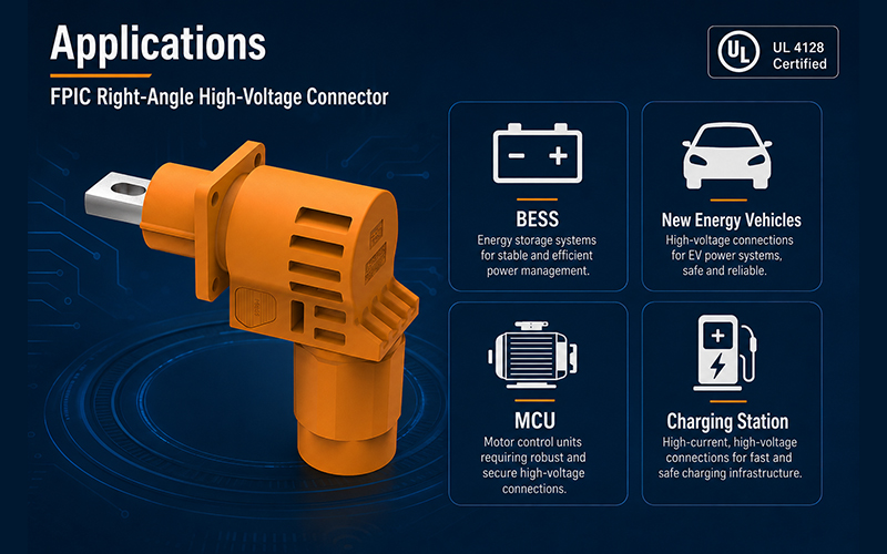
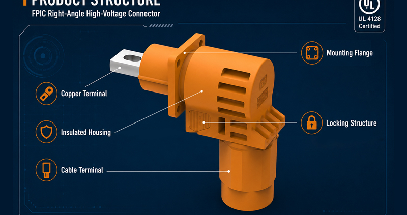
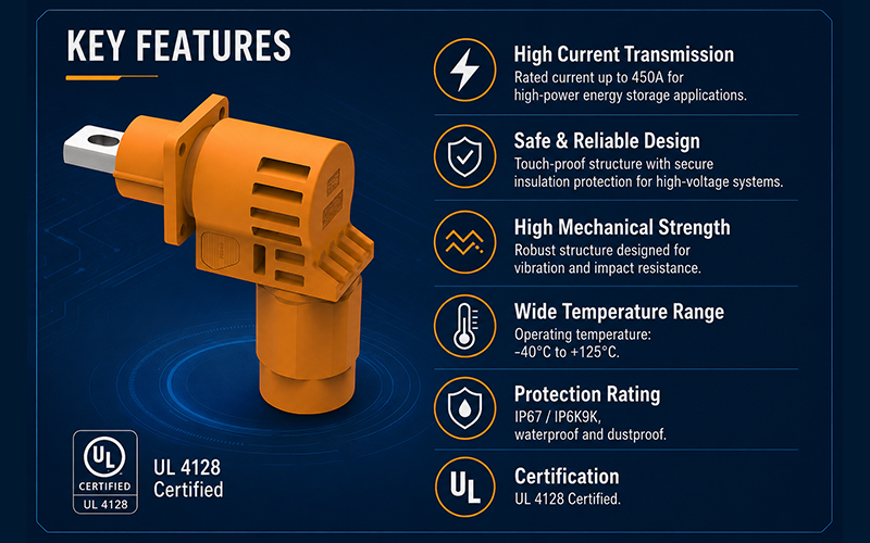
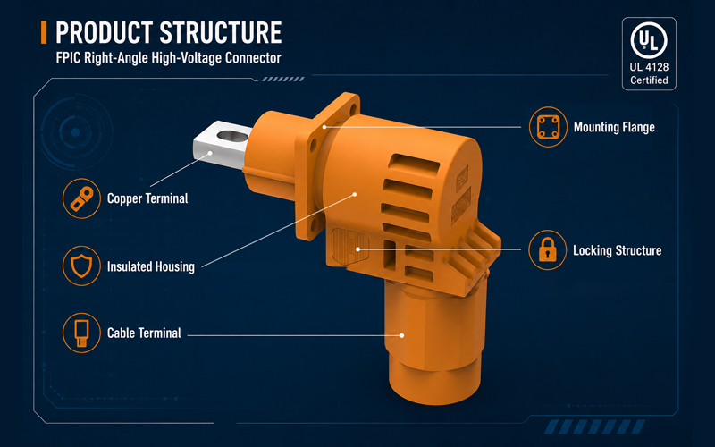
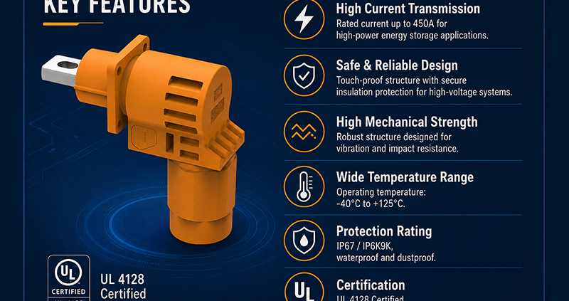
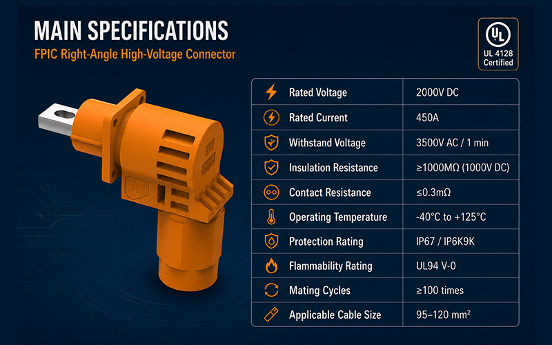
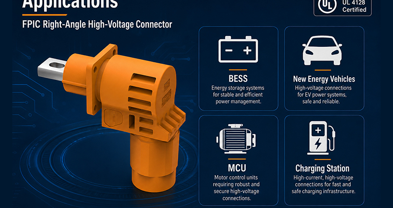
FPIC is pleased to announce that representative samples of our 2000V 450A energy storage connector series have been evaluated by UL for use in electrochemical battery system applications. The certification documents identify the product under UL 4128, 5th Edition, covering intercell and intertier connectors for battery system use.

This milestone strengthens FPIC’s capability in high-current battery interconnection solutions and provides additional confidence for customers developing energy storage equipment, battery packs, and related power distribution systems.

What This Certification Covers

According to the UL Certificate of Compliance, the evaluated product category is BBTH2 – Intercell and Intertier Connectors for Use in Electrochemical Battery System Applications – Component, with certificate number UL-US-26118764-0 and report reference E533832-20260524. The issue date is 2026-05-25.

The corresponding UL report describes the product as:

  • Cable Connectors
    Cat. Nos. A083-1F14-C150N-6A-##, A083-1F14-C150N-5A-##, A083-1F14-C150N-0A-##
  • Panel Mounted Inlets
    Cat. Nos. A083-2M14-E014F-6A-##, A083-2M14-E014F-5A-##, A083-2M14-E014F-0A-##

The report also states the key ratings of this series as 2000V DC and 450A. For the cable connector version, the evaluated conductor size is 300 kcmil.

FPIC 450A Energy Connector Meets UL 4128

Why This Matters for Energy Storage Applications

High-current battery connection points in energy storage systems demand more than basic electrical performance. They also require controlled insulation design, reliable mating, proper polarity identification, and suitability for integration into complete battery equipment.

The UL report identifies these products as intercell/intertier connectors intended for use in electrochemical battery equipment, including cable connector and panel mounted inlet configurations. The panel mounted inlet versions are intended for factory assembly onto copper conductors rated 90°C or higher and/or copper or copper alloy busbars in battery equipment.

For ESS manufacturers, battery pack integrators, and related equipment developers, this provides an important compliance reference point when evaluating connector solutions for high-voltage, high-current battery system designs.

Key Product Characteristics

Based on the UL report, FPIC’s 450A connector series includes the following core characteristics:

1. High Voltage and High Current Capability

The evaluated series is rated at 2000V DC and 450A, supporting demanding battery interconnection applications.

2. Cable and Panel-Mounted Configurations

The series includes both cable connector and panel mounted inlet versions, helping customers build matching connection interfaces for different battery system architectures.

3. Single-Pole Intercell / Intertier Connector Design

The report describes the cable connector products as insulated, single-pole mating intercell/intertier connectors, suitable for battery system connection needs.

4. Support for Battery Equipment Integration

The panel mounted inlet versions are intended for assembly to busbars or conductors in electrochemical battery equipment, which is especially relevant for energy storage cabinets, battery packs, and related systems.

Important Compliance Note

The UL certificate clearly states that these are UL Recognized components, not complete end-use equipment. It also states that the certificate itself does not provide authorization to apply the UL Recognized Component Mark; only products bearing the appropriate UL Recognized Component Mark and covered under UL follow-up services should be considered UL Certified within that program context.

In addition, the UL report notes that these devices are:

  • not suitable for disconnecting under load
  • not intended for use outside an equipment enclosure
  • not investigated for an environment rating
  • intended for use only in complete equipment where acceptability is determined in the end-use application

This is important for customers who are designing certified end products and need to evaluate the connector as part of the complete system.

What This Means for FPIC Customers

This UL milestone demonstrates FPIC’s continued progress in energy storage connector development and supports our ability to serve customers with more robust interconnection solutions for battery system applications.

For customers working on:

  • energy storage systems
  • electrochemical battery equipment
  • battery pack integration
  • power distribution interfaces
  • high-current cabinet connections

this development provides stronger confidence in FPIC’s capability to support demanding connector projects with both product development and manufacturing execution.

FPIC Energy Storage Connector Capability

FPIC has been continuously developing energy storage connector solutions for high-current and high-voltage applications. Our energy storage product direction includes connector and cable solutions designed for battery modules, battery packs, and related ESS equipment. FPIC’s internal product materials also describe energy storage connectors with features such as touch-proof design, multiple connection methods, and compliance direction aligned with UL 4128.

This new 450A certification-related progress further strengthens FPIC’s position in the energy storage connector segment.

Contact FPIC for Energy Storage Connector Projects

If you are developing battery packs, ESS cabinets, or related electrochemical battery equipment and need a reliable high-current connector solution, FPIC can support your project with product information, engineering communication, and manufacturing support.

Contact us to discuss your application requirements.

EV High-Voltage Shielding Overview

Electric vehicles contain some of the most electrically demanding environments in modern engineering.

Inverters, DC/DC converters, onboard chargers, and fast-switching traction systems generate significant electromagnetic noise. Without effective shielding, this noise can interfere with communication networks, sensors, and vehicle electronics.

While shielded cable is an essential first step, overall EMC performance depends heavily on how the shield is terminated through the connector system.

This article explains how high-voltage connector shielding works, common design pitfalls, and the validation methods used to verify EMC performance.


Why Shielding Matters in EV High-Voltage Systems

Typical EV high-voltage cables connect:

  • battery pack
  • inverter
  • onboard charger
  • DC/DC converter
  • electric compressor
  • PDU

These circuits carry high current with rapid switching edges, producing both conducted and radiated emissions.

Potential consequences of poor shielding include:

  • CAN and Ethernet communication errors
  • sensor disturbances
  • failed EMC compliance tests
  • unintended controller resets

Connector shielding helps maintain continuous low-impedance paths for high-frequency currents.

EV High-Voltage Shielding Overview


Basic Shielding Principle

Cable shields work by directing high-frequency noise currents to chassis ground.

For shielding to be effective, the current path must remain continuous across:

  • cable shield
  • backshell
  • connector shell
  • equipment enclosure

Any discontinuity increases impedance and reduces attenuation.


360° Shield Termination

The most effective approach is a full circumferential, or 360°, shield termination.

This method:

  • maximizes shield coverage
  • minimizes transfer impedance
  • avoids long pigtails
  • improves high-frequency performance

Pigtail terminations are generally less effective at high frequencies.


Connector Design Elements for Shielding

High-voltage shielded connectors may include:

  • metal shells
  • conductive backshells
  • spring fingers
  • shield clamps
  • conductive gaskets

These components maintain electrical continuity between cable shield and vehicle chassis.


Grounding Strategy

Shield termination usually connects to chassis ground.

Key considerations include:

  • low contact resistance
  • corrosion protection
  • stable mechanical retention
  • compatibility with system grounding architecture

The objective is low impedance across the relevant frequency range.


Transfer Impedance and Shield Effectiveness

Shield performance is often characterized by transfer impedance.

Lower transfer impedance generally indicates better shielding effectiveness.

Connector design, material choice, and termination quality all influence this parameter.


Common Design Mistakes

Long Shield Pigtails

Increase inductance and degrade high-frequency shielding.

Incomplete Circumferential Contact

Creates local impedance discontinuities.

Poor Corrosion Resistance

Raises contact resistance over time.

Weak Mechanical Retention

Allows micro-motion and fretting.

Discontinuous Shield Path

Reduces attenuation effectiveness.


Mechanical and Environmental Requirements

Shield terminations must remain effective under:

  • vibration
  • thermal cycling
  • humidity
  • salt spray
  • mechanical shock

EMC performance must be maintained throughout the product life.


Validation Methods

Typical validation tests include:

  • shield continuity resistance
  • transfer impedance measurement
  • radiated emissions
  • conducted emissions
  • bulk current injection (BCI)
  • vibration and thermal aging followed by EMC retest

Testing before and after environmental exposure is essential.


Relationship Between Shielding and HV Safety

Shield design must coexist with high-voltage requirements such as:

  • creepage and clearance
  • insulation resistance
  • HiPot withstand
  • touch safety

EMC and safety requirements must be balanced within the same connector package.


Typical Applications

Shielded high-voltage connectors are used in:

  • battery-to-inverter cables
  • onboard charger connections
  • DC fast charging interfaces
  • electric compressors
  • ESS power systems

How FPIC Supports Shielded HV Connector Design

FPIC provides custom high-voltage connector and cable assembly solutions featuring:

  • 360° shield termination
  • integrated backshells
  • HVIL support
  • sealing and mechanical locking
  • continuity, IR, HiPot, and EMC-related validation

Our engineering team helps customers optimize both electrical safety and EMC performance.


Final Thoughts

In EV systems, shielding performance depends on the entire connector and cable assembly—not just the cable itself.

A reliable design requires:

  • continuous shield paths
  • low-impedance termination
  • corrosion-resistant grounding
  • mechanical robustness
  • environmental validation

Effective connector shielding is a key contributor to EMC compliance and system reliability.


FAQ

Why is 360° shield termination preferred?

It minimizes inductance and provides superior high-frequency performance.

What is transfer impedance?

A measure of how effectively a shield limits noise transfer.

Can a cable shield work with a poor connector termination?

No. Connector termination is often the determining factor in overall shielding effectiveness.

Does corrosion affect EMC?

Yes. Increased contact resistance raises shield impedance.

Should EMC performance be tested after vibration?

Yes. Mechanical stress can degrade shield continuity.


Need High-Voltage Connectors with Robust Shielding Performance?

FPIC designs custom shielded high-voltage connectors and cable assemblies for EV and energy storage systems.

Contact us to discuss your EMC and high-voltage interconnect requirements.


Resources

  1. CISPR 25 – Vehicle EMC Requirements
    Standard for radiated and conducted emissions in vehicles.
  2. ISO 11452 – Road Vehicle EMC Immunity Testing
    EMC immunity test methods including BCI.
  3. LV214 – Automotive Connector Validation Standard
    Environmental and electrical requirements for automotive connectors.
  4. TE Connectivity – Shield Termination Design Guide
    Practical guidance on 360° shield grounding.
  5. Molex – High-Voltage Shielded Connector Solutions
    Connector design approaches for EV EMC performance.
HVIL Connector Working Principle

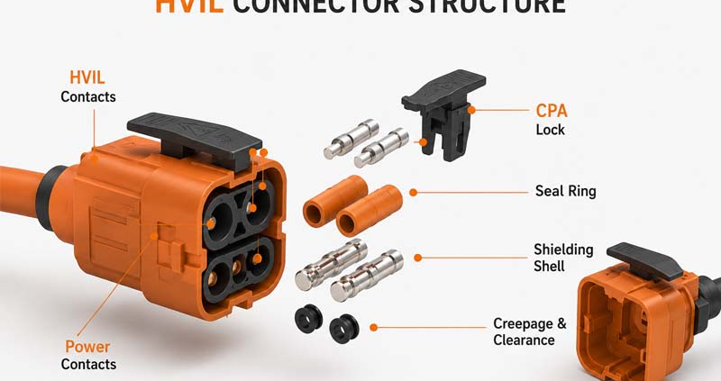
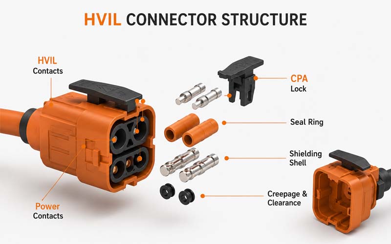
In electric vehicles (EVs), battery energy storage systems (ESS), and other high-voltage applications, electrical safety extends far beyond insulation and creepage distance.

One of the most important safety mechanisms is the High Voltage Interlock Loop (HVIL).

HVIL circuits continuously monitor whether high-voltage connectors, service disconnects, and enclosures are properly engaged. If the loop is interrupted, the control system immediately disables the high-voltage contactors.

Although the HVIL circuit carries only a low-voltage signal, its reliability is essential to the safe operation of the entire system.

This article explains how HVIL connectors work, common failure modes, and the validation tests used to ensure robust performance.

HVIL Connector Working Principle


What Is HVIL?

HVIL stands for High Voltage Interlock Loop.

It is a low-current monitoring circuit that passes through:

  • battery pack connectors
  • inverter connectors
  • onboard chargers
  • DC fast charging interfaces
  • service disconnects
  • high-voltage enclosures

When all connectors are fully mated and covers are closed, the loop remains intact.

If any component is opened or partially disconnected, the loop opens and the system shuts down high voltage.


Why HVIL Is Important

HVIL helps protect:

  • service technicians
  • assembly operators
  • end users
  • vehicle electronics

Typical safety functions include:

  • disabling contactors before connector separation
  • detecting incomplete mating
  • monitoring service access covers
  • preventing energized exposure

In most EV architectures, HVIL is part of the functional safety strategy.


Basic HVIL Operating Principle

The battery management system (BMS) or vehicle control unit injects a low-voltage signal through the interlock loop.

The controller monitors:

  • loop continuity
  • resistance value
  • voltage level

If the signal falls outside expected limits, a fault is triggered.

Some systems use simple open/closed detection, while others use resistor coding to identify specific components.


HVIL Connector Design Features

A dedicated HVIL connector typically includes:

  • two low-voltage interlock contacts
  • staggered contact lengths
  • early-break / late-make sequencing
  • CPA locking features
  • sealed housing
  • mechanical polarization

The HVIL contacts are usually designed to disconnect before the high-voltage power contacts separate.


Early-Break / Late-Make Concept

HVIL contacts are intentionally longer or shorter than power contacts.

During Unmating

The HVIL circuit opens first, allowing contactors to open before high-voltage contacts separate.

During Mating

Power contacts are fully engaged before the HVIL loop closes.

This sequencing is critical to system safety.


Common HVIL Failure Modes

1.Contact Fretting

Micro-motion can increase resistance and cause intermittent loop faults.

2.Incomplete Mating

If the connector is not fully seated, HVIL continuity may be unstable.

3.Terminal Back-Out

Improper terminal retention can interrupt the circuit.

4.Corrosion or Water Ingress

Moisture may increase resistance or cause open circuits.

5.Broken HVIL Wires

Small-gauge wires are vulnerable to fatigue and handling damage.

6.Contaminated Contacts

Debris or oxidation can degrade signal integrity.


Design Considerations for Reliable HVIL Performance

Key design priorities include:

  • stable low-current contact resistance
  • robust terminal retention
  • vibration-resistant locking
  • environmental sealing
  • clear mating confirmation
  • protected wire routing

Because HVIL circuits carry very low current, they are especially sensitive to contamination and fretting.


Validation Test Points

Typical validation activities include:

  • contact resistance measurement
  • mating and unmating force
  • terminal retention force
  • vibration testing
  • thermal cycling
  • humidity exposure
  • salt spray
  • sealing tests
  • mechanical shock

Functional monitoring should verify that the HVIL circuit opens and closes in the correct sequence.


Critical Functional Checks

During validation, engineers should confirm:

  • HVIL opens before power contacts disengage
  • HVIL closes only after full mating
  • resistance remains within specification
  • no intermittent opens occur during vibration
  • CPA and locking systems function correctly

Standards and Specifications

Relevant standards may include:

  • LV214
  • USCAR-2
  • OEM high-voltage connector specifications
  • ISO 6469
  • ISO 26262

Requirements vary by customer and application.


Typical Applications

HVIL connectors are widely used in:

  • EV battery packs
  • inverters
  • PDU (Power Distribution Units)
  • onboard chargers
  • DC fast charge systems
  • ESS battery cabinets

How FPIC Supports HVIL Connector Projects

FPIC provides custom high-voltage connector and cable assembly solutions with:

  • integrated HVIL circuits
  • sealed connector designs
  • CPA and TPA features
  • continuity, IR, and HiPot testing
  • application engineering support

We help customers develop reliable high-voltage interconnect systems for EV and energy applications.


Final Thoughts

HVIL connectors carry only a low-voltage signal, but they play a critical role in high-voltage safety.

  • A robust design requires:
  • correct contact sequencing
  • stable low-current performance
  • secure mechanical locking
  • environmental protection
  • thorough validation

In EV systems, the reliability of the HVIL circuit is essential to protecting both people and equipment.


FAQ

What does HVIL stand for?

High Voltage Interlock Loop.

What happens when the HVIL circuit opens?

The system commands the high-voltage contactors to open and disables high voltage.

Why are HVIL contacts sequenced differently from power contacts?

To ensure the safety circuit opens before high-voltage contacts separate.

Can corrosion cause HVIL faults?

Yes. Low-current circuits are highly sensitive to contamination and corrosion.

Is HVIL required in EV systems?

It is widely used as a core safety mechanism in high-voltage architectures.


Developing High-Voltage Connectors with HVIL?

FPIC provides custom high-voltage connectors and cable assemblies with integrated HVIL solutions for EV, ESS, and industrial applications.

Contact us to discuss your design and validation requirements.


Resources

  1. ISO 6469 – Electrically Propelled Road Vehicles Safety Specifications
    Safety requirements for EV high-voltage systems.
  2. LV214 – Environmental and Electrical Requirements for Automotive Connectors
    Automotive connector validation standard widely used by OEMs.
  3. USCAR-2 – Performance Specification for Automotive Connectors
    Defines connector reliability and environmental tests.
  4. ISO 26262 – Functional Safety for Road Vehicles
    Functional safety framework for automotive systems.
  5. TE Connectivity – HVIL Design Concepts
    Technical guidance on high-voltage interlock connector design.
Plastic Mold Design Standardization Guide

Plastic mold design standardization reduces rework, shortens lead time, improves interchangeability, and makes mass production more stable. For engineering teams, it is not just a documentation exercise. It is a practical system for mold bases, side actions, runners, gates, locating features, and ejection structures.

If you want faster mold development and more predictable molding results, standardize five things first: the mold base platform, movement structures, runner and gate logic, locating features, and ejection design. That approach helps engineering teams reduce variation, simplify purchasing, improve maintenance, and make quality more repeatable from prototype to mass production.

Below is a practical guide built from FPIC’s internal engineering standard and aligned with widely accepted industry thinking. It is written for buyers, product engineers, and mold teams who want better control over cost, quality, and launch timing.

What Plastic Mold Design Standardization Really Means

Plastic mold design standardization means using defined rules for mold platforms, standard components, structural calculations, gating logic, locating methods, and ejection choices instead of redesigning every detail from scratch. In practice, this shortens design cycles, improves repeatability, and makes molds easier to build, inspect, repair, and scale across product families.

That industry logic is consistent with FPIC’s internal engineering presentation, which starts standardization with mold-base selection, preferred materials, ordering rules, datum logic, and standard machining expectations before moving into side actions, runners, locating, and ejection.

Why Standardization Pays Off

Standardization is valuable because mold performance depends on many linked decisions. A well-defined mold base platform makes procurement and machining more predictable. Standard side-action rules reduce assembly risk. Balanced runner logic helps filling consistency. Repeatable ejection rules reduce part damage and maintenance time.

For companies serving automotive, medical, industrial, and connector programs, this matters even more. Product families often share similar geometries, tolerance expectations, and validation paths. A standardized mold design approach makes design reviews faster and engineering decisions easier to reuse.

Faster Engineering Decisions

When design rules are already clear, engineers spend less time debating routine choices and more time solving real product-specific challenges.

Better Manufacturing Consistency

Standard platforms and structures reduce dimensional variation, simplify machining, and improve assembly accuracy.

Easier Mold Maintenance

A mold built on standard logic is easier to inspect, repair, and modify during long production runs.

Start with a Standard Mold Base Strategy

FPIC’s engineering standard identifies two common mold-base types: a large sprue mold base and a simplified pin-point gate mold base. It also specifies common reference suppliers, mold-base material in the S50C–S55C range, and common core materials such as S136, SKD61, DC53, and VIKING. The same internal standard also requires chamfering of machined edges, default dimensioning from the datum corner unless otherwise stated, and standardized ordering logic for mold-base sizes and plate thicknesses.

Why the Mold Base Matters

The mold base is the structural foundation of the tool. A standardized base improves rigidity, purchasing efficiency, and machining predictability.

Why the Mold Base Matters

Material Selection Should Not Be Arbitrary

Mold-base and core material choices directly affect wear resistance, heat treatment stability, polishing behavior, and maintenance cycles.

Standard Ordering Reduces Errors

Using a consistent ordering format for mold-base size, plate thickness, and supplier requirements reduces communication mistakes and speeds up purchasing.

Standard Ordering Reduces Errors


Standardize Movement Structures Before They Become Problems

Slides, hydraulic side actions, first-return mechanisms, and lifters are common failure points when teams rush concept work. FPIC’s engineering standard gives clear rules here: slide geometry follows defined angular relationships, hydraulic cylinders must not be used to seal off plastic directly, first-return mechanisms are required when ejectors sit under moving members, and lifter angles are generally kept in the 3°–10° range while ensuring no interference with surrounding parts or the molded product.

Slide Design Should Follow Fixed Geometry Rules

Slide systems work best when angular relationships, guide structures, and clearance rules are standardized early.

Hydraulic Structures Need Safety Logic

Hydraulic cylinders can add flexibility, but they also introduce sealing and timing risks if used incorrectly.

Lifter Design Must Balance Motion and Part Safety

Lifters must avoid interference with both the product and neighboring components, while also preventing scraping or plastic damage during ejection.


Treat Runner and Gate Design as a System

FPIC’s internal standard treats the gating system as a structured decision set. It defines nozzle-to-sprue relationships, locating-ring use, runner cross-section choices, runner layout logic, and gate selection guidance. It specifically notes that round and trapezoidal runners are both common, that multi-cavity runner layouts should prioritize balanced filling, that H-shaped distribution generally gives better balance than T-shaped layouts, and that different gate types serve different production goals.

Runner Geometry Affects More Than Flow

Runner shape and size influence pressure drop, thermal loss, filling balance, and cycle stability.

Gate Selection Should Match the Product Goal

Submarine gates support automation. Large sprues are simple but often manual. Pin gates improve automatic separation but raise mold complexity.

Balanced Layouts Improve Multi-Cavity Stability

A balanced runner system helps ensure that all cavities fill more consistently, reducing quality variation between parts.


Make Locating Features Do More Than Just Align Parts

A good mold does not rely on memory. It relies on features that prevent mistakes. FPIC’s internal standard makes this clear by treating locating structures as a core method to prevent assembly errors and preserve mold precision. It also recommends insert-level locating to prevent rotation or incorrect assembly, and it uses anti-error design when a part is not center-symmetric or when left/right variants exist.

Mold Accuracy Starts with Repeatable Positioning

Stable locating improves assembly precision and reduces accumulated tolerance errors inside the tool.

Anti-Mistake Design Saves Real Cost

Simple anti-error structures can prevent reversed assembly, insert rotation, and rework during tool build or maintenance.


Ejection Rules Should Protect Parts and Tool Life

Ejection design is another area where standardization saves money quickly. FPIC’s internal standard prioritizes ejector placement near ribs or high-release-force areas, requires enough distance between water channels and ejector pins, encourages fewer ejector-pin size variations in a single tool, and defines when to switch from pins to sleeve ejection, push blocks, or stripper plates. It also calls for vent grooves in sleeve ejectors to reduce thermal friction and wear.

Ejector Pins Are Not Always the Best Answer

Pins are efficient, but deep bosses, thin walls, and cosmetic surfaces may require sleeves, push blocks, or stripper plates.

Standard Pin Layout Rules Improve Stability

Uniform pin placement and limited pin-size variation simplify machining, assembly, and future maintenance.

Venting and Clearance Protect the Tool

Vent grooves and proper spacing reduce friction, sticking, and heat-related wear during long production runs.


A Practical 5-Step Standardization Framework

If you want to build or upgrade your own plastic mold design standardization system, use this sequence:

Step 1 – Lock the Platform

Define preferred mold-base families, suppliers, base materials, and standard machining scope.

Step 2 – Lock the Motion Rules

Standardize slide, cylinder, first-return, and lifter geometry before detailed 3D work starts.

Step 3 – Lock the Flow Logic

Create a gating decision table by resin, part size, cosmetic requirement, and automation goal.

Step 4 – Lock Locating and Mistake-Proofing

Use consistent locating features for mold bases, inserts, and asymmetrical parts.

Step 5 – Lock the Ejection Decision Tree

Define when to use pins, sleeves, blocks, and stripper plates, plus spacing and venting rules.

This is the point where standardization stops being a document and starts becoming a productivity tool.


What Buyers and Product Engineers Should Ask Mold Suppliers

If you are outsourcing tooling, ask these five questions before approving design freeze:

  1. Do you use a standard mold-base system?
  2. How do you standardize slides, lifters, and hydraulic side actions?
  3. How do you choose runner layout and gate type for this resin and part geometry?
  4. What locating features prevent assembly mistakes and insert rotation?
  5. What is your standard ejection strategy for ribs, deep bosses, and cosmetic surfaces?

A supplier that answers clearly is more likely to control risk later.


Where FPIC Adds Value

At FPIC, we view mold design standardization as part of product quality, not just tooling efficiency. That matters for connector programs, precision plastic parts, and complex assemblies where dimensional consistency, cosmetic control, and repeatable mass production all matter. Our internal engineering standard covers mold-base selection, side-action logic, runner and gate decisions, locating, and ejection in a structured way, and it is supported by our broader manufacturing focus on automation, process discipline, and scalable production.

We do not recommend over-standardizing blindly. Some parts need exceptions. But a good standard should make exceptions visible and intentional. That is usually the difference between a mold that merely works and a mold that works predictably over time.

If you are developing precision plastic parts, connector components, or custom tooling programs, FPIC can support manufacturability review, tooling optimization, and scalable production planning.


Conclusion

Plastic mold design standardization is one of the fastest ways to improve tooling quality without adding unnecessary complexity. Done well, it reduces variation, accelerates design reviews, improves maintainability, and supports more stable mass production.

If you are evaluating a new tooling partner or trying to improve internal mold performance, start with the five areas above. If you need support on precision plastic parts, connector tooling, or manufacturability review, FPIC’s engineering and manufacturing teams can help you move from concept to stable production with fewer surprises.


References / Notes

  1. FPIC internal engineering presentation: R&D Dept., compiled by Zhu Xiaolong, 2026.04.14. This article incorporates FPIC’s internal design rules for mold bases, side actions, runners, locating, and ejection.
  2. HASCO, Specifications for Injection Moulds 2.0 and HASCO standard mold-unit information.
  3. DME, official mold-base, mold-component, CAD, and technical-guide resources.
  4. Protolabs Network (formerly Hubs), Injection Molding Design Guide.
  5. Ma et al., research on standard component libraries for plastic injection mold design.
  6. Mold-Masters, discussion of runner balance and shear effects.
Square Pin Terminals vs. Automotive Rounded Pin Terminals

A square pin terminal works well in standard PCB headers and low-vibration electronics. An automotive rounded pin terminal is built for stronger guidance, better vibration resistance, improved self-cleaning contact, and higher long-term reliability. If the application is automotive or high-reliability industrial equipment, the rounded automotive design is usually the better choice.

The main difference is not just the shape. Standard square pin terminals prioritize easy insertion and low cost for general electronics, while automotive rounded pin terminals are designed for vibration resistance, guided mating, stable contact, and long service life in harsher environments. Their structure, stamping process, plating method, and performance targets are all different.

If you only look at the pin tip, the difference may seem small. In real applications, though, terminal geometry affects contact stability, corrosion resistance, plating consistency, insertion feel, and even failure risk over time. This article breaks down the differences step by step so engineers, sourcing teams, and product managers can make better design decisions.

Start With the Right Terminology

Before comparing the products, it is important to use the right language.

In this article:

  • Standard square pin terminal means the square or flat-edged metal pin commonly used in PCB pin headers.
  • Automotive rounded pin terminal means the rounded or bullet-shaped male terminal used in automotive low-voltage connector systems.

This distinction matters because industry-leading suppliers do not treat pin headers and terminals as the same category. Aptiv’s public connection systems catalog lists Connectors, Terminals, Seals, and Pin Headers as separate product groups, which confirms that “pin header” and “automotive terminal” should not be used interchangeably.

Why This Comparison Matters

Automotive connectors work in a very different environment from ordinary board-level connectors.

According to VDA, electrical and electronic components in vehicles must continuously adapt to stricter requirements around safety, reliability, environmental exposure, vibration, temperature, and chemical resistance. VDA also highlights that wiring systems and connector components are part of that evolving standardization work.

That is why a terminal for a vehicle cannot be chosen the same way as a terminal for a simple PCB header. Even if both parts are conductive metal pins, the design priorities are different:

  1. Consumer electronics focus more on cost, compactness, and ease of assembly
  2. Automotive systems focus more on durability, vibration stability, and long-term consistency
  3. Harsh environments require stronger protection against debris, contact instability, plating wear, and corrosion

FPIC’s internal technical comparison document makes the same point very clearly: a standard square pin terminal is meant for lower-stress electronic connections, while the automotive rounded pin terminal is designed for high-vibration, high-reliability service conditions.

Structural Differences

Square Pin Terminals vs. Automotive Rounded Pin Terminals

Standard Square Pin Terminals

A standard square pin terminal usually has:

  • Tip: Sharp/pyramidal, small flat surface, obvious edges
  • Root: 90° dead-angle
  • Design focus: Easy insertion, low cost, for consumer electronics (low vibration, few insertions)
  • Example applications: PCB headers, low-end electronic devices, DuPont-style wiring

This kind of structure is common in:

  • Board-to-board connections
  • Standard PCB headers
  • Consumer electronics
  • Simple control boards
  • Low-vibration devices

The main benefits are easy insertion, easy manufacturing, and lower cost. But the structure also has limitations. Sharp edges and dead corners can create areas where stress concentrates, and in demanding environments they are less forgiving.

Automotive Rounded Pin Terminals

An automotive rounded pin terminal usually has:

  • Tip: Rounded bullet-head / dome-shaped
  • Root: Smooth tapered transition, no dead corner
  • Pin body: Thicker, stronger
  • Core benefits: Guided insertion, vibration resistance, self-cleaning, short-circuit protection
  • Designed for automotive harsh conditions: ECU, BCM, lighting, window, seat control modules

This design offers several practical advantages:

  • Better insertion guidance
  • Reduced scraping at the mating interface
  • More stable contact behavior
  • Better vibration resistance
  • Lower risk of debris staying in sharp dead corners
  • Improved contact reliability over long service life

Structural Comparison Table

ItemStandard Square Pin TerminalAutomotive Rounded Pin Terminal
Tip shapeSharp / pyramidal / flat-edgedRounded / bullet-shaped / dome-like
Root transition90° style transition, dead-corner tendencySmooth tapered transition
Edge conditionObvious corners and flat facesRounded surface, fewer stress points
Contact styleFlat or edge-dominantArc-guided, more stable engagement
Main design goalEasy insertion, simple structure, lower costGuidance, vibration resistance, reliability
Typical environmentGeneral electronicsAutomotive low-voltage systems
Debris toleranceLowerBetter
Reliability expectationBasicHigh

Why Rounded Geometry Helps in Automotive Use

The rounded automotive design is not just about appearance. It changes how the terminal behaves during mating and in long-term service.

1. Better Guidance

A rounded tip helps the male terminal find its way into the mating contact more smoothly. This matters when connector tolerances, insertion angle variation, or assembly speed introduce small alignment changes.

2. Better Vibration Resistance

In vehicles, connectors see repeated vibration from engine systems, road conditions, opening and closing actions, and general operating movement. A more robust and better-guided terminal geometry helps maintain a stable contact relationship.

3. Better Self-Cleaning Behavior

When two contacts mate and unmate repeatedly, a rounded guided structure can help wipe the contact area more consistently. FPIC’s internal document specifically notes this self-cleaning advantage as one reason automotive rounded terminals better resist contamination-related issues.

4. Lower Short-Circuit Risk

The internal comparison also notes that the absence of obvious dead-angle geometry helps reduce the chance of debris buildup around the terminal root, which is one of the practical design benefits of the automotive rounded form.

Industry Background and Design Thinking

FPIC’s internal document cites historical automotive field-failure discussions as a turning point in how the industry views low-voltage terminal design. The document explains that older low-voltage connector approaches using more ordinary square-pin-like forms could create higher risk when vibration, thermal cycling, and debris were involved, which pushed the market toward more robust automotive-specific terminal geometry.

Even without repeating every historical claim, the design lesson is clear:

Automotive connectors are not just “stronger consumer connectors.” They are engineered differently because the environment is different.

That view also aligns with the broader work of VDA and USCAR, where connector systems and related specifications are continuously reviewed to meet the demands of safety, durability, and vehicle operating conditions.

Manufacturing Process Differences

The structure difference is only one part of the story. The manufacturing route is also very different.

How Standard Square Pin Terminals Are Made

  • Equipment: Multi-wheel forming machines
  • Process: Wire extrusion → straightening → forming → cutting
  • Output: Loose independent pins
  • Automation: Limited
  • Use case: Standard PCB headers

How Standard Square Pin Terminals Are Made

How Standard Square Pin Terminals Are Made

How Automotive Rounded Pin Terminals Are Made

  • Equipment: High-speed precision stamping, continuous progressive dies
  • Process: Brass strip → stamping → punching → bending → forming → cutting
  • Output: Continuous strip carrier for automated assembly
  • Automation: High compatibility, precise dimensions, supports reel-to-reel plating

How Automotive Rounded Pin Terminals Are Made

Manufacturing Comparison Table

ItemStandard Square Pin TerminalAutomotive Rounded Pin Terminal
Main equipmentMulti-wheel square pin forming machineHigh-speed precision stamping press
Input materialWire stockCopper alloy strip
Core processExtrusion/forming/cuttingProgressive stamping/forming
Finished formLoose pin / independent pinContinuous carrier strip
Automation compatibilityMediumHigh
Dimensional controlBasic to mediumHigher
Mass-production suitabilityGood for standard electronicsBetter for automotive-scale process control

Plating Process Differences

The plating route is one of the biggest technical differences, and it directly affects contact quality.

Standard Square Pin Terminal Plating

  • Barrel/batch plating
  • Less uniform coating; edges and tips prone to thin plating
  • Manual sorting required for automation

Automotive Rounded Pin Terminal Plating

  • Reel-to-reel continuous precision plating
  • Uniform thickness, strong adhesion
  • Fully compatible with automated assembly, injection molding, and SMT

Plating Comparison Table

ItemStandard Square Pin TerminalAutomotive Rounded Pin Terminal
Workpiece formLoose individual pinsContinuous strip terminal
Typical plating methodBarrel / bulk platingReel-to-reel precision plating
Thickness consistencyLowerHigher
Edge coverage consistencyLess stableBetter controlled
Adhesion behaviorMore variationMore stable
Automation supportLimitedExcellent

Performance Comparison

FPIC’s internal technical comparison gives a clear picture of why automotive rounded terminals are chosen for more demanding systems.

MetricSquare PinRounded Pin
Contact resistanceHigh batch variationLow, ≤±1mΩ
Mating cycles≤500>10,000
Vibration resistanceLowHigh, car-grade
Salt spray resistancePoor>10 years in automotive environment
Current carryingLocal heatingUniform, stable temperature rise
Temperature toleranceLimited-40°C to +125°C
High-frequency signalPoorLVDS compatible, stable signal

Industry Standards & Background

  1. Early Mercedes W210/W220 ECU/BCM PCB failures due to square pins → large recalls, safety issues
  2. USCAR / VDA / QC/T standards: automotive ≥2-pin low-voltage connectors must use rounded bullet-head terminals
  3. Safety, vibration, long-term reliability, and manufacturing precision are mandatory in automotive-grade terminals

Application Comparison

Best Uses for Standard Square Pin Terminals

A standard square pin terminal is usually a good fit for:

  • PCB headers
  • Consumer electronics
  • Low-vibration control boards
  • Cost-sensitive electronics
  • Standard signal connections

Best Uses for Automotive Rounded Pin Terminals

An automotive rounded pin terminal is usually the better fit for:

  • Automotive low-voltage systems
  • Control modules
  • Lighting systems
  • Window lift systems
  • Power seat systems
  • Multimedia systems
  • Industrial equipment with demanding vibration requirements
  • Long-life signal or low-voltage power transmission

FPIC Engineering Perspective

At FPIC, terminal selection is not treated as an isolated metal-part decision. It is part of the full connector-system design process.

A good connector terminal must be evaluated together with:

  • Housing design
  • Material selection
  • Plating specification
  • Contact force
  • Current path
  • Assembly process
  • Testing method
  • End-use environment

This system-level mindset also matches FPIC’s broader manufacturing strengths. According to FPIC company materials, the company supports connector development through:

  • Product design and tooling development
  • Metal stamping
  • Plastic injection molding
  • Auto assembly with CCD
  • Quality assurance testing
  • Automotive connector manufacturing under IATF 16949-related systems and process control

That manufacturing foundation matters because a good terminal design only delivers real value when it can also be produced consistently.

What Engineers and Buyers Should Ask Before Selecting a Terminal

When reviewing a connector concept, ask these questions:

1) What is the real operating environment?

Will the connector see:

  • Road vibration?
  • Temperature cycling?
  • Moisture?
  • Corrosive conditions?
  • Repeated mating?

If yes, a general square pin may not be the right solution.

2) Is insertion feel important?

Rounded automotive terminals generally provide smoother and more forgiving insertion behavior, especially when alignment is not perfect.

3) How important is long-term consistency?

If the product must stay reliable over years, especially in automotive or industrial systems, terminal geometry and plating consistency become much more important.

4) Will the part be made at scale?

If the project needs high automation, stable dimensions, and controlled plating, strip-based automotive-style terminal production has strong advantages.

Practical Selection Guide

Application ScenarioRecommended ChoiceWhy
Standard PCB headerStandard square pin terminalCost-effective and suitable for simple board-level use
Consumer electronicsStandard square pin terminalEnough performance for lower-stress environments
Automotive low-voltage connectorAutomotive rounded pin terminalBetter vibration resistance and long-term reliability
Signal connector in harsh industrial equipmentAutomotive rounded pin terminalBetter guidance and contact stability
High-reliability long-life designAutomotive rounded pin terminalBetter process consistency and service performance

Conclusion

A standard square pin terminal and an automotive rounded pin terminal may look similar at first glance, but they are built for different jobs.

The square pin version is a practical choice for general electronics where cost and simplicity matter most. The automotive rounded version is designed for a tougher world: vibration, temperature change, longer service life, and higher reliability requirements.

So if the project is automotive, or if the application behaves more like automotive in terms of durability demands, the safer decision is usually the automotive rounded terminal.

FAQ

1. Is a pin header the same as an automotive terminal?

No. A pin header usually refers to a connector category used on PCBs, while an automotive terminal refers to a terminal system designed for vehicle-grade electrical connection. Leading supplier catalogs treat them as separate categories.

2. Why are automotive terminals often rounded?

Because the rounded shape improves insertion guidance, reduces sharp-edge stress, supports more stable mating, and performs better in vibration-heavy environments.

3. Are square pin terminals bad?

Not at all. They are a good solution for the right application. The issue is not quality, but fit. They are simply intended for less demanding operating conditions than automotive terminals.

4. Does plating really make a big difference?

Yes. Plating consistency affects contact resistance, corrosion resistance, wear behavior, and long-term performance. Reel-to-reel precision plating generally offers better consistency for automotive terminals.

5. When should I choose the automotive rounded design?

Choose it when the connector must survive vibration, repeated mating, wider temperature exposure, and longer service life requirements.

Ready to choose the right terminal for your automotive or industrial application?

Explore FPIC’s complete range of low-voltage automotive connectors and bullet-head terminals for high-reliability, vibration-resistant, and long-life performance.

View Products: https://fpiconn.com/products/

Contact Sales: info@fpiconn.com

💡 Tip: Our engineering team can help you select the right terminal and connector solution for your exact application, including rapid prototyping and mass-production guidance

Resources

  1. FPIC Internal Technical Document: “Differences Between Automotive Low-Voltage Connector Terminals and Standard Pin Header Terminals”
    This internal FPIC source provided the core technical comparison for structure, process route, plating method, performance differences, and application recommendations used in this article.
  2. Aptiv – Connection Systems Catalog
    Aptiv’s official catalog clearly separates Terminals and Pin Headers into different product categories, which supports the terminology distinction used in this article.
    Link: https://www.aptiv.com/en/solutions/connection-systems/catalog
  3. VDA – Electrical/Electronic Components and General System Requirements
    VDA explains that automotive electrical and electronic components must continuously adapt to requirements involving safety, reliability, vibration, temperature, chemicals, and other operating conditions.
    Link: https://www.vda.de/en/topics/automotive-industry/standardization-and-technical-standards/e-e-components-and-general-system-requirements
  4. USCAR – EWCAP / Connector Validation Context
    USCAR materials help show the broader North American automotive context for connector and terminal validation work.
    Link: https://uscar.org/