How to Specify High-Current Connectors for Industrial Equipment
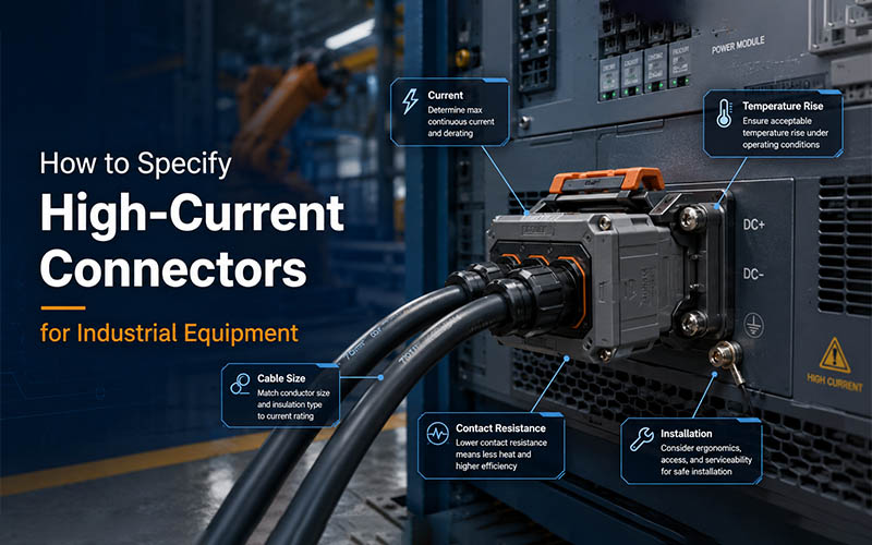
Industrial power connections are moving beyond permanently bolted busbars and screw-terminal blocks. Pluggable interfaces can shorten assembly time, simplify maintenance, and support modular equipment—but only when current, cable size, temperature rise, contact resistance, vibration, and installation conditions are evaluated together.
To specify a high-current connector, define the continuous and peak current, system voltage, conductor size, permitted temperature rise, contact resistance, environmental exposure, vibration level, termination method, mating frequency, and maintenance requirements. Final selection should be validated under actual equipment conditions.
The highest ampere value in a catalog is not automatically the best choice. A technically sound selection matches the complete electrical, thermal, mechanical, and service environment of the machine.
Why Industrial Power Connection Design Is Changing
Traditional high-power equipment commonly uses bolted busbars, cable lugs, or screw-terminal blocks. These methods remain suitable for many fixed installations, but they may require tools, controlled tightening torque, sufficient working space, and trained technicians.
They can also make module replacement slower. When an inverter, motor controller, battery module, power supply, heater, or distribution unit must be removed, technicians may need to isolate the system, remove covers, release multiple fasteners, and verify tightening torque during reassembly.
Modern industrial equipment is increasingly modular. Machine builders want components that can be assembled, replaced, and serviced with less downtime. This is driving greater use of pluggable power interfaces in applications ranging from approximately 20A to 500A DC.
However, converting a bolted connection into a plug-and-socket interface does not remove engineering risk. It changes where that risk must be controlled.
The connector now needs to maintain:
- low and stable electrical resistance;
- acceptable thermal performance;
- secure mechanical engagement;
- suitable protection against dust and moisture;
- resistance to shock, vibration, and temperature cycling;
- repeatable cable termination;
- safe installation and maintenance procedures.
A pluggable solution therefore should be selected as part of the equipment architecture—not as a catalog accessory added near the end of the project.
Start with the Actual Electrical Load
The first task is to define how the equipment really operates.
A useful specification should distinguish between:
- continuous operating current;
- temporary overload current;
- startup or inrush current;
- regenerative or reverse current;
- duty cycle;
- system voltage;
- expected ambient temperature;
- allowable voltage drop.
A machine that draws 250A continuously creates a different thermal condition from one that reaches 250A for only a few seconds. Likewise, an interface installed in a ventilated electrical cabinet behaves differently from the same interface placed beside a motor, heater, converter, or enclosed battery module.
1. Continuous Current
Continuous current determines the long-term thermal load on the contact system, terminal, cable, and surrounding enclosure.
The published rating should be treated as a starting point. Engineers should confirm the conditions under which it was established, including:
- ambient temperature;
- conductor cross-section;
- number of energized contacts;
- enclosure condition;
- permitted temperature rise;
- test method.
2. Peak and Transient Current
Peak current can occur during motor starting, capacitor charging, welding cycles, hydraulic pump activation, inverter operation, or battery discharge.
A short peak may not heat the complete cable significantly, but it can still create local stress at the contact interface. The connector manufacturer should therefore understand both the magnitude and duration of the peak.
3. Voltage and Insulation Requirements
Voltage selection affects more than the printed voltage rating. The design must also consider:
- clearance and creepage distance;
- insulation material;
- pollution degree;
- altitude;
- overvoltage category;
- touch protection;
- grounding requirements;
- whether connection or disconnection could occur while energized.
High current and high voltage are separate design variables. A product with sufficient ampere capacity may still be unsuitable for the required insulation environment.
Match the Cable Size to the Current and Terminal
Cable size cannot be selected independently from the connector.
The conductor must carry the required load without excessive voltage drop or thermal stress, while the terminal barrel must be designed for the same conductor class and cross-section.
Important cable variables include:
- copper or aluminum conductor;
- conductor cross-sectional area;
- AWG or metric size;
- strand class and flexibility;
- insulation diameter;
- insulation temperature rating;
- cable bending radius;
- shielded or unshielded construction.
A terminal designed for 50 mm² cable should not be assumed to perform correctly with a smaller or larger conductor merely because it can be physically inserted.
Incorrect conductor-to-terminal matching may cause:
- incomplete conductor compression;
- excessive voids inside the crimp;
- broken strands;
- low pull-out strength;
- unstable resistance;
- localized overheating;
- poor sealing at the cable entry.
1. Cable Size Does Not Determine Current Alone
A larger conductor generally offers lower resistance, but safe current capacity still depends on insulation temperature, bundling, ventilation, cable length, installation method, and ambient conditions.
The complete current path should be reviewed—from the source and cable to the terminal, contact interface, panel inlet, busbar, and load.
2. Consider Routing and Mechanical Load
Large power cables can apply substantial force to an interface.
During layout review, check:
- cable exit direction;
- minimum bending radius;
- unsupported cable weight;
- strain relief;
- torsional load;
- side load on the receptacle;
- available installation space.
An electrically correct interface can still fail prematurely if the cable continuously pulls or twists the mating pair.
Evaluate Temperature Rise, Not Just Rated Current
Current creates heat wherever electrical resistance exists.
The basic relationship is:
Power loss = Current² × Resistance
This means that a small increase in resistance becomes much more important as current rises.
For example, doubling current increases resistive heat by a factor of four when resistance remains unchanged. This is why milliohm-level changes matter in high-power equipment.
1. What Causes Temperature Rise?
Temperature rise at an interface can be affected by:
- contact resistance;
- conductor resistance;
- terminal material;
- contact geometry;
- normal contact force;
- plating condition;
- crimp quality;
- ambient temperature;
- enclosure airflow;
- adjacent heat sources;
- contamination or corrosion;
- cable size.
Temperature-rise testing and current-temperature derating are recognized methods for assessing connector current-carrying capacity. The selected interface should be verified at the expected ambient temperature rather than assumed safe from a room-temperature catalog value.
2. Why Derating Is Necessary
A connector tested in open air at 25°C may operate differently inside a sealed cabinet at 55°C.
As ambient temperature rises, less thermal margin remains before the terminal, housing, seal, or cable insulation approaches its allowable limit.
Derating may also be necessary when:
- several power contacts are energized together;
- connectors are installed close to each other;
- airflow is restricted;
- cable bundles retain heat;
- the equipment operates continuously;
- contamination affects heat dissipation.
3. Validate the Complete Assembly
Temperature testing should include the actual or representative:
- connector pair;
- cable cross-section;
- crimp or termination process;
- cable length;
- panel mounting arrangement;
- enclosure environment;
- current profile.
Testing only an isolated contact may not reveal the real thermal behavior of the final assembly.
Control Contact Resistance Throughout Service Life
Low initial resistance is important, but stable resistance over time is more important.
The contact system should maintain sufficient normal force and a clean conductive interface after exposure to vibration, mating cycles, temperature changes, and environmental contamination.
1. Main Sources of Resistance Growth
Resistance may increase because of:
- insufficient contact pressure;
- contact wear;
- fretting corrosion;
- surface oxidation;
- contamination;
- damaged plating;
- loose termination;
- conductor strand movement;
- thermal expansion and contraction;
- improper mating.
As resistance increases, the interface generates more heat. Additional heat can accelerate oxidation, stress relaxation, housing deformation, or insulation aging, creating a self-reinforcing failure process.
2. Contact Material and Plating
The correct contact material and finish depend on current density, mating frequency, environment, and cost requirements.
Common considerations include:
- copper-alloy conductivity;
- spring performance;
- silver, tin, or gold contact finish;
- plating thickness;
- wear resistance;
- corrosion protection;
- compatibility between mating surfaces.
The lowest-cost plating is not always the lowest lifecycle-cost solution. It should be selected according to the actual operating environment and expected service life.
3. Measure Resistance Correctly
Contact resistance should be measured using a defined test method and stable fixture conditions. Measurements should be compared:
- before environmental testing;
- after vibration;
- after thermal cycling;
- after mating durability;
- after corrosion or humidity exposure.
The change in resistance often reveals more about long-term reliability than the initial value alone.
Account for Vibration and Thermal Cycling
Industrial equipment may experience continuous vibration from motors, pumps, compressors, fans, mobile platforms, machining processes, or vehicle movement.
Vibration can create small relative movements at the contact interface. Over time, this may cause fretting, plating wear, resistance drift, or loosening.
Thermal cycling creates a different mechanical load. Metals, plastics, seals, conductors, and housings expand and contract at different rates. Repeated cycles can affect:
- contact force;
- terminal retention;
- crimp stability;
- sealing;
- fastener torque;
- housing geometry.
Questions to Ask During Selection
- Is the interface intended for stationary or mobile equipment?
- What vibration frequency and acceleration are expected?
- Will the cable move independently from the enclosure?
- Is a secondary locking feature required?
- Can the connection be inspected visually?
- Has resistance been measured after vibration testing?
- Will the equipment experience rapid hot-to-cold transitions?
A high current rating does not compensate for insufficient mechanical retention.
Choose the Right Installation Method
The best connection method depends on how the equipment is manufactured, installed, and serviced.
| Installation method | Main advantages | Main considerations |
| Bolted busbar | High current capacity and compact fixed joint | Requires torque control, tools, access, and inspection |
| Cable lug and stud | Familiar and widely available | Assembly time and loosening risk must be managed |
| Screw terminal | Flexible field wiring | Torque and conductor preparation affect reliability |
| Crimped pluggable connector | Fast assembly, repeatable termination, easier replacement | Requires correct tooling and process control |
| Push-in or spring connection | Fast wiring and reduced retightening | Must match conductor size and application current |
| Panel-mount plug and receptacle | Supports modular equipment and service access | Requires correct panel strength, sealing, and cable routing |
1. Crimp Termination
A controlled crimp creates a gas-tight mechanical and electrical joint without solder.
Key controls include:
- correct terminal and wire combination;
- specified crimp height;
- conductor position;
- bellmouth condition;
- insulation support;
- pull-force testing;
- cross-section analysis;
- calibrated tooling.
FPIC’s internal crimping requirements emphasize conductor crimp height, insulation support, visible conductor position, pull-force testing, and cross-section inspection as core quality controls.
2. Panel-Mount Interfaces
Panel-mounted receptacles can simplify equipment modularity, but the panel design must support:
- mounting loads;
- mating and unmating forces;
- vibration;
- sealing surfaces;
- busbar or cable attachment;
- service access.
The connector should not be expected to compensate for a weak mounting panel or unsupported cable.
Define Maintainability Before Freezing the Design
Maintainability should be a design requirement, not an afterthought.
Ask how technicians will isolate, access, disconnect, inspect, replace, and reconnect the component.
A pluggable system may reduce:
- equipment replacement time;
- field wiring errors;
- dependence on torque tools;
- access space requirements;
- production assembly time;
- machine downtime.
However, these benefits depend on correct interface design.
1. Useful Service Features
Depending on the application, useful features may include:
- clear polarity or position coding;
- mechanical keying;
- visible locking confirmation;
- touch-safe contacts;
- secondary locking;
- tool-free release;
- replaceable cable assemblies;
- accessible test points;
- defined mating sequence.
2. Prevent Disconnection Under Load
Many industrial connectors are not intended to interrupt operating current.
The equipment design should clearly define:
- isolation procedure;
- interlock requirements;
- lockout/tagout method;
- whether an auxiliary contact is needed;
- whether the connector can be accessed while energized.
A serviceable interface is not automatically a switching device.
Specify Environmental Protection Correctly
Industrial equipment may operate in clean indoor cabinets, dusty production areas, outdoor machinery, washdown zones, or corrosive environments.
The specification should define:
- dust and water exposure;
- IP requirement in mated and unmated condition;
- operating temperature;
- humidity;
- salt spray or chemical exposure;
- UV exposure;
- altitude;
- shock and impact;
- flammability requirement.
Do not select an IP rating without checking when it applies. Some products achieve the stated protection only when fully mated and correctly assembled with the specified seals and cable diameter.
Use a Complete Engineering Specification
A practical RFQ should provide more than a desired ampere value.
| Specification item | Information to provide |
| Application | Machine, inverter, motor, battery, heater, power supply, distribution unit |
| Voltage | Nominal, maximum, AC or DC |
| Current | Continuous, peak, duration, and duty cycle |
| Cable | Material, cross-section, strand class, outer diameter |
| Temperature | Ambient, internal cabinet, cable and terminal limits |
| Environment | Indoor, outdoor, dust, water, oil, chemicals, salt |
| Mechanical load | Vibration, shock, cable movement, mating cycles |
| Installation | Panel, cable-to-cable, busbar, PCB, blind mate |
| Termination | Crimp, screw, stud, busbar, push-in |
| Safety | Touch protection, coding, grounding, interlock |
| Maintenance | Replacement frequency, tool access, service time |
| Compliance | Required IEC, UL, EN, railway, automotive, or customer standards |
Providing these details allows a manufacturer to recommend an interface based on the real system rather than simply matching a catalog current rating.
How FPIC Supports Industrial Power Connection Projects
FPIC develops and manufactures connectors, cable assemblies, terminals, and precision components for industrial equipment and high-power applications.
Our support can include:
- application and drawing review;
- conductor and terminal matching;
- custom connector structure development;
- cable assembly and crimping support;
- material and plating evaluation;
- mold and stamping-tool development;
- prototype validation;
- temperature-rise and electrical testing;
- vibration, thermal-shock, and mechanical testing;
- automated assembly and inspection;
- scalable production support.
FPIC’s industrial connector capability includes rugged power, signal, and cable-assembly solutions for equipment that requires stable electrical performance, vibration resistance, environmental protection, and controlled production quality.
Our laboratory and inspection capabilities include temperature-rise testing, contact-resistance measurement, insertion and extraction testing, thermal shock, vibration testing, X-ray inspection, dimensional measurement, and cleanliness inspection.
For qualified custom development projects, FPIC can also provide end-to-end support from product review and tooling through validation and mass-production preparation.
A Practical Selection Workflow
Use the following seven-step process when specifying an industrial power interface:
1. Define the Current Profile
Document continuous current, overload, peak duration, and duty cycle.
2. Confirm Voltage and Safety Requirements
Define insulation, touch protection, grounding, coding, and disconnection rules.
3. Select the Conductor
Match cable size, strand class, insulation rating, and routing requirements.
4. Establish the Thermal Limit
Define maximum ambient temperature and allowable temperature rise.
5. Review Mechanical Conditions
Evaluate vibration, shock, cable load, mating cycles, and locking requirements.
6. Choose the Installation Architecture
Compare bolted, screw, crimped, panel-mounted, and pluggable solutions according to production and maintenance needs.
7. Validate the Final Assembly
Test the real cable, termination, connector pair, mounting method, current profile, and environmental conditions.
Frequently Asked Questions
1. Is the catalog current rating enough for connector selection?
No. The rating must be reviewed together with ambient temperature, cable size, enclosure conditions, duty cycle, contact resistance, and allowable temperature rise.
2. Why does cable size affect connector performance?
The conductor size influences resistance, heat generation, crimp quality, voltage drop, cable flexibility, and the terminal design required for reliable termination.
3. What causes an industrial power connector to overheat?
Common causes include excessive current, unstable contact resistance, poor crimping, an undersized conductor, contamination, loose mating, damaged plating, and insufficient heat dissipation.
4. Are pluggable connectors better than bolted busbars?
Not in every application. Pluggable products improve modularity and serviceability, while bolted busbars remain effective for fixed, compact, very-high-current connections. The correct choice depends on operating and maintenance requirements.
5. Should temperature rise be tested in the final equipment?
Yes. Final validation should use a representative cable, termination, mounting arrangement, enclosure, ambient temperature, and electrical load.
Conclusion
A reliable industrial power interface cannot be selected by current rating alone.
The final decision must connect electrical load, conductor size, thermal performance, contact stability, vibration resistance, environmental protection, installation method, and maintenance strategy.
When these factors are evaluated together, pluggable power connectors can help equipment manufacturers shorten assembly time, improve modularity, reduce service effort, and build more reliable industrial systems.
Discuss Your Industrial Power Connection Project
FPIC supports customized connector and cable-assembly development for industrial equipment, high-voltage systems, and high-current power interfaces.
Send us your application requirements, current and voltage ratings, cable specification, drawings, and operating conditions for engineering evaluation.
Email: info@fpiconn.com
Resources
- Connector Supplier – How to Specify High-Current Connectors for Industrial Equipment
- IEC 60512-5-1 – Current-Carrying Capacity Tests: Temperature Rise
- IEC 60512-5-2 – Current-Temperature Derating
- IEC 60512-2-1 – Contact Resistance Test Method
- TE Connectivity – Heavy-Duty Industrial Connectors
- Phoenix Contact – Heavy-Duty Connectors
- HARTING – Industrial Rectangular Connectors
- Materion – How Much Current Can Safely Run Through a Connector?
- KYOCERA AVX – Criteria for Selecting Connectors for Industrial Applications