Smaller electronic systems increasingly combine high-speed signals, wireless functions, power conversion, sensors, and control circuits on densely populated PCBs. Under these conditions, connector selection affects more than pin count and mating height.

A compact connector must also support signal integrity, current delivery, mechanical stability, manufacturability, and electromagnetic compatibility.

Quick Answer:

EMI shielding improves PCB connector reliability by limiting electromagnetic energy entering or leaving the connection interface. An effective shield, combined with a low-impedance grounding path and correct PCB layout, can reduce noise, crosstalk, data errors, and EMC compliance risks.

Molex’s recent Quad-Row Shield announcement illustrates this industry direction. The connector combines a four-row contact layout with an integrated metal shield. Molex reports up to a 25 dB EMI reduction compared with its unshielded Quad-Row version, while samples are available for custom inquiries and commercial supply is planned for the second quarter of 2026.

However, a metal cover alone does not guarantee reliable electromagnetic performance. Engineers must evaluate the connector, PCB grounding, enclosure, contact layout, cable paths, power distribution, and application environment as one system.


Why EMI Becomes More Difficult in Compact PCB Systems

Miniaturization places more electrical functions into a smaller physical area. Signal traces, power contacts, antennas, switching regulators, clocks, processors, sensors, and communication circuits may operate only millimeters apart.

This creates several potential interference paths:

  • noise generated by switching power circuits;
  • radiation from high-speed digital signals;
  • coupling between adjacent contacts;
  • interference entering through openings in an enclosure;
  • current flowing through poorly controlled ground paths;
  • transient noise from motors, relays, converters, or wireless transmitters.

A conventional connector may provide adequate electrical continuity while still allowing interference to couple across the board interface.

This is particularly important when the system includes:

  • high-speed serial communication;
  • cameras or display modules;
  • radar or wireless functions;
  • compact automotive control modules;
  • medical or measuring equipment;
  • industrial sensors and controllers;
  • mixed power-and-signal interfaces.

Molex identifies controlled impedance, reduced crosstalk, and EMI shielding as important features for optimizing PCB layout, signal integrity, and system performance in mezzanine connectors.

What EMI Shielding Does at the Connector Interface

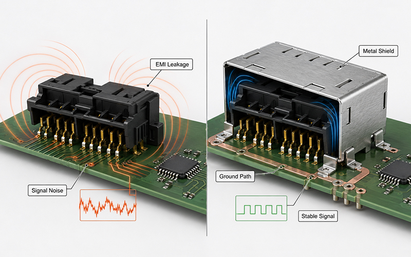
A connector shield forms a conductive barrier around or near the signal contacts. When properly grounded, this structure helps control electromagnetic fields around the mating interface.

Its primary functions include:

What EMI Shielding Does at the Connector Interface

1. Reducing Radiated Emissions

Fast signal edges and switching currents can cause the connector and adjacent PCB structures to radiate electromagnetic energy.

A conductive shield helps contain part of this energy before it reaches nearby circuits, antennas, sensors, or the external environment.

2. Improving Immunity to External Noise

The same barrier can reduce the amount of external interference that reaches sensitive contacts.

This becomes important when connectors operate near:

  • DC/DC converters;
  • motors and actuators;
  • wireless antennas;
  • high-current conductors;
  • relays and solenoids;
  • vehicle power electronics.

3. Controlling Crosstalk

Crosstalk occurs when energy from one signal path couples into another.

Shielding can reduce field coupling, but pin assignment, contact spacing, ground-contact placement, differential-pair routing, and return-path design remain equally important.

4. Supporting EMC Compliance

Integrated shielding may simplify the path toward electromagnetic compatibility because it controls interference closer to the source.

Molex states that its shielded Quad-Row design can reduce EMI, support stringent EMI/EMC requirements, and lower the regulatory testing burden. This is a supplier-reported product benefit rather than a guarantee that any completed device will pass certification automatically.

The complete product must still be tested in its final configuration.


Shielding Effectiveness Depends on the Ground Path

One of the most common design errors is treating the metal shield as an isolated component.

A shield only works effectively when interference current can flow through a controlled, low-impedance path to ground or chassis.

Engineers should examine:

  • how the shield contacts the PCB;
  • the number and location of grounding points;
  • the length of the grounding path;
  • PCB ground-plane continuity;
  • enclosure contact around the interface;
  • gaps between mating shield components;
  • whether the shield remains continuous after mating.

At higher frequencies, a long or narrow grounding path can behave inductively. This limits the shield’s effectiveness even when DC continuity appears satisfactory.

For this reason, shielding design should begin during connector and PCB development—not after the first EMC test failure.

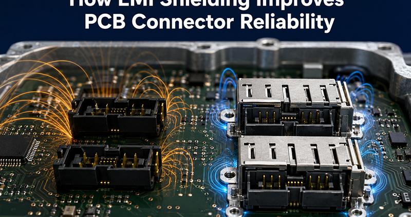
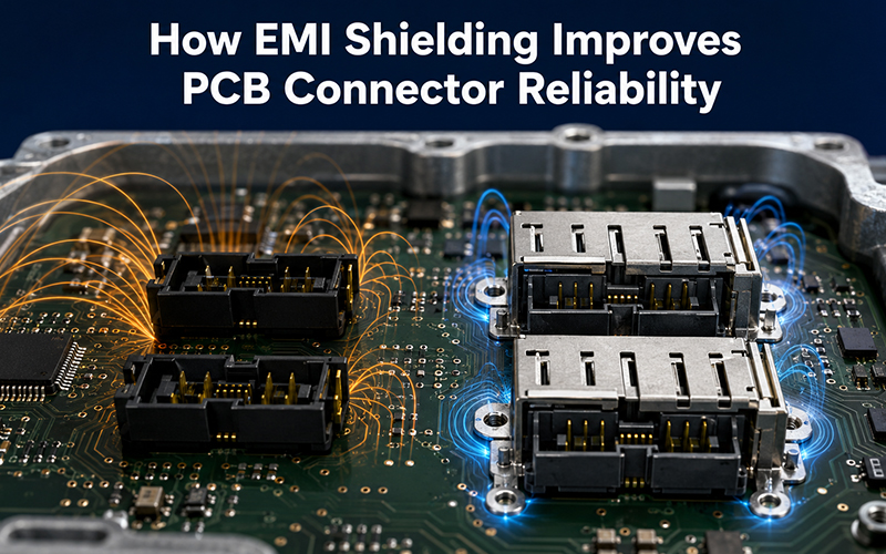
How EMI Shielding Improves PCB Connector Reliability

EMI Shielding and Signal Integrity Are Related but Different

EMI and signal integrity are closely connected, but they are not identical.

EMI design controls unwanted electromagnetic energy entering or leaving a system.

Signal-integrity design ensures that the intended signal reaches the receiver with acceptable timing, amplitude, noise margin, and waveform quality.

A shield may reduce external noise while the signal still suffers from:

  • impedance discontinuity;
  • reflections;
  • poor return paths;
  • excessive insertion loss;
  • skew between differential traces;
  • crosstalk inside the contact field.

For high-speed interfaces, engineers may need to evaluate:

  • insertion loss;
  • return loss;
  • near-end and far-end crosstalk;
  • differential impedance;
  • S-parameters;
  • eye-diagram performance;
  • contact assignment and grounding strategy.

Molex states that preferred pin layouts and S-parameter input specifications may be assigned within the 80-pin Quad-Row Shield design. This shows that shielding and contact mapping must be engineered together rather than evaluated separately.


Miniaturization Must Not Reduce Power Reliability

Modern compact connectors increasingly carry both signal and power.

This creates a difficult design balance:

  • more contacts in less PCB area;
  • higher current density;
  • less space for heat dissipation;
  • greater sensitivity to contact resistance;
  • stronger interaction between power noise and signal circuits.

Molex describes its Quad-Row architecture as supporting up to 80 pins and substantially more signal and power connections than a single-pin interface. Its product page lists current capability in the approximate 2.6–3.0 A-per-contact range for typical configurations, while the wider Molex board-to-board portfolio includes different product families for substantially higher current requirements.

This does not mean every contact can carry the maximum value simultaneously under all conditions.

Current capability depends on:

  • conductor and terminal geometry;
  • number of simultaneously energized contacts;
  • contact resistance;
  • ambient temperature;
  • PCB copper area;
  • enclosure airflow;
  • duty cycle;
  • permitted temperature rise.

When power and sensitive signals share one interface, engineers should consider using dedicated ground contacts, separating power from high-speed pairs, and validating the final assembly through temperature-rise and electrical testing.


When Does a PCB Connector Need EMI Shielding?

Not every application requires a shielded interface.

Adding shielding can increase component complexity, tooling requirements, PCB grounding needs, and cost. It should therefore solve a defined electromagnetic problem.

Shielding deserves serious consideration when one or more of the following conditions apply.

1. High-Speed Signals Cross the Interface

Interfaces carrying high-speed differential data, camera signals, displays, radar data, Ethernet, or other fast digital communication are more sensitive to discontinuities and interference.

2. The Connector Is Close to a Noise Source

Risk increases when the connector sits near switching regulators, high-current traces, motors, relays, inverters, wireless transmitters, or inductive loads.

3. The Product Has Limited Enclosure Shielding

A plastic enclosure or a large opening around the connector may offer little control over radiated energy.

An integrated connector shield can help close part of this electromagnetic gap.

4. The System Has Strict EMC Requirements

Automotive, industrial, medical, aerospace, and communication equipment often face demanding immunity and emission requirements.

A shielded interface may provide additional design margin, although system-level testing remains necessary.

5. Power and Signal Contacts Share Limited Space

Mixed power-and-signal layouts may introduce switching noise, ground bounce, and thermal constraints.

Shielding can be part of the solution, but contact allocation and PCB return-path design are equally important.


Connector Shielding Cannot Correct a Poor PCB Layout

A shielded component may still perform poorly when the surrounding PCB layout creates uncontrolled interference paths.

Engineers should coordinate the connector design with the board layout.

1. Maintain a Continuous Reference Plane

High-speed signals need a stable return path.

Avoid unnecessary ground-plane splits beneath the connector and around the signal escape region.

2. Place Ground Connections Close to the Shield

Short, wide ground connections generally provide lower impedance than long, narrow traces.

Multiple grounding points may improve current distribution and reduce shield discontinuities.

3. Separate Sensitive Signals from Noisy Power Paths

Avoid routing sensitive differential pairs next to switching nodes, inductors, motor outputs, or high-current conductors.

4. Minimize Stubs and Abrupt Geometry Changes

Unused branches, long breakout paths, and sudden changes in trace width or reference plane can increase reflection and noise.

5. Coordinate PCB and Enclosure Grounding

The connector shield, board ground, chassis, and external enclosure should follow a deliberate grounding strategy.

Connecting them without understanding the return-current path can create new coupling problems.

Mechanical Design Also Affects Shielding Reliability

Connector shielding must remain effective after assembly, vibration, temperature cycling, and repeated mating.

A mechanically weak shield may lose contact pressure, deform, or create gaps that reduce electromagnetic performance.

Important mechanical considerations include:

  • shield retention in the housing;
  • mating alignment;
  • solder-joint strength;
  • board hold-down features;
  • resistance to connector peeling or lifting;
  • vibration and shock resistance;
  • durability over the required mating cycles;
  • protection against handling damage.

Molex uses an armored, insert-molded nail and internal cover in its Quad-Row family to improve mechanical robustness and reduce mating damage. The company also states that the design supports conventional SMT production and high-volume reel packaging.

For automotive and industrial applications, the connector design may also need to consider:

  • temperature cycling;
  • vibration;
  • contamination;
  • housing retention;
  • pin position and coplanarity;
  • solder-joint fatigue;
  • long-term contact-force stability.

Materials and Plating Influence Electrical Performance

Shield performance depends partly on material conductivity, surface condition, mechanical force, and corrosion resistance.

The signal contacts and shield may use different base materials and plating systems according to their functions.

Typical engineering considerations include:

  • electrical conductivity;
  • spring force;
  • formability;
  • wear resistance;
  • solderability;
  • corrosion protection;
  • contact resistance;
  • compatibility with SMT temperatures.

FPIC’s technical materials identify connector contacts and shield-related parts made from copper alloys, stainless steel, and other stamped materials, with plating selected according to conductivity, solderability, corrosion resistance, and cost. They also describe high-temperature polymers such as LCP, PA9T, PA6T, PA46, and PPS for connector applications that must tolerate reflow processing.

Material selection should therefore reflect the complete production and operating environment, not only the connector’s nominal electrical rating.

How Shielded PCB Connectors Should Be Validated

A shielded connector requires more than a dimensional inspection.

Validation should combine electromagnetic, electrical, mechanical, environmental, and manufacturing checks.

Electromagnetic Evaluation

Depending on the project, testing may include:

  • shielding-effectiveness comparison;
  • radiated emissions;
  • conducted emissions;
  • radiated immunity;
  • bulk-current injection;
  • electrostatic discharge;
  • S-parameter characterization;
  • crosstalk and signal-integrity testing.

Electrical Evaluation

Common checks include:

  • contact resistance;
  • insulation resistance;
  • dielectric withstand voltage;
  • current-carrying capacity;
  • voltage drop;
  • temperature rise.

Mechanical Evaluation

Relevant tests may include:

  • mating and unmating force;
  • terminal retention;
  • connector hold-down strength;
  • vibration;
  • mechanical shock;
  • mating durability.

Environmental Evaluation

Depending on the application:

  • thermal cycling;
  • high- and low-temperature exposure;
  • humidity;
  • salt spray;
  • solder-heat resistance;
  • contamination or cleanliness inspection.

Manufacturing Evaluation

For SMT board connectors, engineers should also monitor:

  • pin coplanarity;
  • terminal position;
  • solder-joint geometry;
  • reflow compatibility;
  • pick-and-place handling;
  • shield deformation;
  • automated optical or CCD inspection.

FPIC’s internal capability materials list contact-impedance testing, temperature-rise testing, withstand-voltage and insulation testing, insertion and extraction testing, vibration, thermal shock, X-ray inspection, Keyence dimensional measurement, solder-heat evaluation, and CCD-supported automated production.

These capabilities help support design verification, but the final validation plan should always follow the customer’s application, product specification, and applicable standards.


A Practical Selection Checklist

Before choosing or developing a shielded PCB connector, define the following requirements.

Design areaInformation to confirm
Interface typeBoard-to-board, wire-to-board, header, mezzanine, or hybrid
Contact layoutPin count, pitch, row arrangement, and pin assignment
Signal requirementsProtocol, data rate, impedance, and differential pairs
Power requirementsVoltage, current per circuit, and active-contact count
Shielding objectiveEmissions, immunity, crosstalk, or enclosure continuity
GroundingPCB ground points, chassis path, and shield termination
Mechanical layoutMating height, orientation, retention, and alignment
EnvironmentTemperature, vibration, humidity, dust, and corrosion
ProductionSMT process, reflow profile, packaging, and inspection
ValidationSI, EMC, electrical, mechanical, and environmental tests

A complete requirement set prevents a project from being reduced to “same pitch, same pin count.”

Two connectors with similar dimensions may perform very differently when shielding continuity, current density, material selection, solder-joint strength, and high-speed layout are considered.


How FPIC Supports Custom PCB Connector Development

FPIC develops board-to-board, wire-to-board, automotive PCB header, receptacle, terminal, shielding, and custom interconnection components.

For compact PCB connector projects, engineering support can include:

  • application and drawing review;
  • pitch, pin-count, and mating-height evaluation;
  • contact and housing design;
  • shielding-cover and stamped-metal development;
  • signal and power contact allocation;
  • material and plating selection;
  • precision stamping and insert molding;
  • injection-mold and stamping-tool development;
  • SMT and reflow compatibility review;
  • dimensional, electrical, and mechanical verification;
  • automated assembly and CCD inspection;
  • prototype and scalable production support.

FPIC’s internal connector materials describe board-to-board products ranging from conventional pin headers to fine-pitch, high-density interfaces. They also identify applications combining high-speed signals, lower-speed circuits, and power distribution within one interface.

For automotive projects, FPIC operates under IATF 16949 and supports automotive PCB and low-voltage connector development for applications such as lighting control, power seats, window systems, multimedia modules, and related electronic control assemblies. Its broader manufacturing platform includes in-house tooling, stamping, injection molding, insert molding, automated assembly, testing, and precision-component production.

FPIC does not position every custom PCB connector as an off-the-shelf shielded high-speed product. Instead, shielding, signal performance, current capability, dimensions, materials, and validation requirements should be defined during project review.


Frequently Asked Questions

Does every board-to-board connector need EMI shielding?

No. Shielding is most valuable when high-speed signals, sensitive electronics, strong nearby noise sources, limited enclosure shielding, or strict EMC requirements create a measurable interference risk.

Can a metal connector cover guarantee EMC compliance?

No. It may improve electromagnetic performance, but final compliance depends on PCB layout, grounding, enclosure design, cables, software operating modes, power circuits, and the complete assembled product.

Does shielding improve signal integrity?

It can reduce external interference and coupling, but it cannot correct impedance discontinuities, poor differential routing, excessive loss, or an interrupted return path.

Can power and signal contacts share the same connector?

Yes, provided the contact layout, current density, temperature rise, grounding, isolation, and signal-integrity requirements are properly engineered and validated.

What information is needed for a custom shielded connector?

Provide the 2D or 3D drawings, PCB layout constraints, pitch, pin count, mating height, signal protocol, current requirements, shielding target, grounding concept, production volume, and required tests.


Conclusion

EMI shielding is becoming a functional part of compact connector design rather than an optional metal accessory.

A reliable shielded interface must combine electromagnetic control with suitable grounding, signal mapping, current capacity, thermal performance, mechanical retention, materials, SMT compatibility, and system-level validation.

For equipment manufacturers, the best connector is not simply the smallest one. It is the interface that uses limited PCB space without compromising signal quality, power delivery, production consistency, or long-term reliability.

Discuss Your Custom PCB Connector Project

FPIC supports customized automotive PCB headers, board-to-board connectors, terminals, shielding components, and complete interconnection development.

Send your drawings, PCB constraints, electrical requirements, application conditions, and forecast demand for engineering review.

Email: info@fpiconn.com


Resources

  • Molex. Molex Announces Availability of Industry-First Space-Saving Quad-Row Board-to-Board Connectors with EMI Shields. November 4, 2025.
  • Molex. Quad-Row Connectors—Features, Specifications and Applications.
  • Molex. Mezzanine Connectors.
  • Molex. Board-to-Board Connectors.
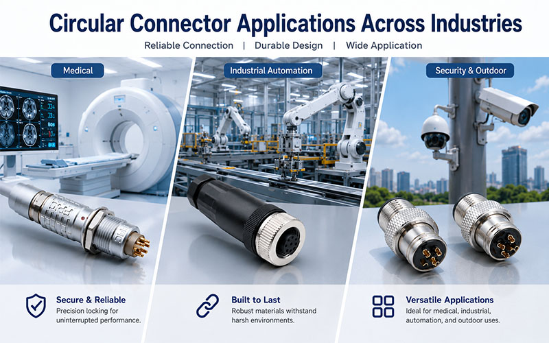
Circular Connector Applications Across Industries

Circular connectors are widely used because they combine compact size, reliable electrical performance, and excellent environmental protection. From medical imaging systems and industrial robots to outdoor automation and renewable energy equipment, they provide dependable connections for power, signal, and data transmission.

However, there is no universal circular connector suitable for every application. A connector designed for a surgical device may not survive on construction machinery, while an outdoor waterproof connector may be unnecessarily large for laboratory equipment.

Selecting the right connector requires balancing electrical performance, environmental protection, mechanical reliability, and maintenance requirements.

This guide explains the most important factors engineers should consider when choosing circular connectors for different industries.

Circular Connector Applications Across Industries


Start with the Application Environment

Before comparing connector specifications, first understand where the connector will operate.

Typical environments include:

Medical Equipment

  • Diagnostic systems
  • Patient monitoring devices
  • Surgical equipment
  • Laboratory instruments

Design priorities:

  • Compact size
  • Frequent cleaning
  • High mating reliability
  • Excellent signal integrity

Industrial Automation

Typical applications include:

  • Industrial robots
  • Servo motors
  • PLC control systems
  • Machine tools
  • Factory automation

Design priorities:

  • Vibration resistance
  • EMC performance
  • High mating durability
  • Reliable locking

Outdoor Equipment

Typical applications include:

  • Renewable energy systems
  • Agricultural machinery
  • Construction equipment
  • Rail transportation
  • EV charging infrastructure

Design priorities:

  • Waterproof sealing
  • UV resistance
  • Corrosion resistance
  • Wide operating temperature

Different environments require different connector designs.


Choose the Appropriate Locking Mechanism

Connector locking directly affects operational reliability.

Common options include:

Push-Pull Locking

Advantages:

  • Fast connection
  • One-hand operation
  • Easy maintenance
  • Secure automatic locking

Ideal for:

  • Medical equipment
  • Laboratory systems
  • Collaborative robots

Threaded Locking

Advantages:

  • Excellent vibration resistance
  • Strong mechanical retention
  • Long-term stability

Ideal for:

  • Industrial automation
  • Servo systems
  • Heavy equipment

Bayonet Locking

Advantages:

  • Quick quarter-turn locking
  • Reliable positioning
  • Outdoor suitability

Ideal for:

  • Portable equipment
  • Field instruments
  • Mobile machinery

Consider Environmental Protection

Environmental sealing is critical when connectors are exposed to dust, water, oil, or cleaning chemicals.

Common protection levels include:

IP Rating                Typical Applications

IP67                         Industrial automation, robotics

IP68                        Outdoor automation, renewable energy

IP69K                      Food processing, washdown equipment, heavy-duty vehicles

The required protection level should match the actual operating conditions rather than simply selecting the highest rating available.


Evaluate EMC Requirements

Modern equipment often combines:

  • Power transmission
  • Industrial Ethernet
  • CAN Bus
  • High-speed data
  • Precision sensors

Shielded circular connectors help:

  • Reduce EMI
  • Improve signal integrity
  • Maintain communication stability
  • Support reliable automation

For high-speed communication, connector shielding should include proper 360° shield termination.


Select the Right Contact Configuration

Connector selection also depends on:

  • Number of contacts
  • Signal type
  • Power rating
  • Mixed power and signal transmission

Many applications combine:

  • Power contacts
  • Signal contacts
  • Data contacts
  • Ground contacts

Hybrid connectors simplify installation while reducing cable complexity.


Consider Mating Cycle Requirements

Some connectors remain installed for years.

Others are connected and disconnected daily.

Typical examples include:

Low Mating Frequency

  • Wind turbines
  • Energy storage systems
  • Control cabinets

High Mating Frequency

  • Medical devices
  • Test equipment
  • Portable instruments

Applications with frequent reconnection should prioritize connectors designed for thousands of mating cycles.


Material Selection Matters

Connector housing materials influence durability and EMC performance.

Common choices include:

Metal Housing

Advantages:

  • Better shielding
  • Higher mechanical strength
  • Improved heat dissipation

Engineering Plastic Housing

Advantages:

  • Lightweight
  • Corrosion resistant
  • Cost-effective

Material selection should reflect the environmental and mechanical demands of the application.


Validate Before Production

Connector selection should always be verified through testing.

Recommended evaluations include:

  • Mating cycle testing
  • Vibration testing
  • Salt spray testing
  • IP protection testing
  • Contact resistance testing
  • EMC verification
  • Temperature cycling

Testing complete connector assemblies under actual operating conditions provides the highest confidence in long-term performance.


How FPIC Supports Circular Connector Applications

FPIC develops circular connectors, push-pull self-locking connectors, waterproof connectors, and customized connectivity solutions for medical equipment, industrial automation, robotics, renewable energy, and outdoor applications.

With more than 23 years of manufacturing experience, our engineering team helps customers select the right connector based on electrical performance, environmental requirements, mechanical reliability, and application-specific standards. From prototype development to mass production, FPIC provides dependable connector solutions designed for long-term performance.


Final Thoughts

Choosing the right circular connector involves much more than selecting the correct number of contacts.

Engineers must consider the operating environment, locking mechanism, environmental sealing, EMC performance, durability, and maintenance requirements together

Whether designing a medical device, an industrial robot, or an outdoor energy system, selecting the appropriate connector improves equipment reliability, simplifies maintenance, and reduces lifecycle costs.


FAQ

What factors should be considered when choosing a circular connector?

Key factors include application environment, IP protection, locking mechanism, shielding, contact configuration, mating cycles, and environmental durability.

Which locking mechanism is best for medical equipment?

Push-pull connectors are widely used in medical equipment because they provide fast, secure, one-handed operation and support frequent mating cycles.

Is IP69K always better than IP67?

Not necessarily. The appropriate IP rating should match the operating environment. Higher protection levels may increase size and cost without adding practical benefits.

When are shielded circular connectors required?

Shielded connectors are recommended for applications involving Industrial Ethernet, CAN Bus, servo systems, or environments with significant electromagnetic interference.

Why is mating cycle life important?

Applications requiring frequent connection and disconnection need connectors with high mating durability to maintain reliable electrical performance over time.


Looking for the Right Circular Connector for Your Application?

Whether you’re designing medical equipment, industrial automation systems, or outdoor electrical installations, FPIC provides high-quality circular connectors, push-pull self-locking connectors, and waterproof connectivity solutions tailored to your application. Our engineering team can help you select the ideal connector for reliable performance in demanding environments.

Contact FPIC today to discuss your circular connector requirements.


Resources

  1. IEC 61076 – Connectors for Electrical and Electronic Equipment
    https://webstore.iec.ch/
    Provides international standards for the design, performance, and testing of circular and industrial connectors.
  2. IEC 60529 – Degrees of Protection Provided by Enclosures (IP Code)
    https://webstore.iec.ch/
    Defines IP67, IP68, and IP69K protection ratings for connectors used in industrial and outdoor environments.
  3. IEC 60601-1 – Medical Electrical Equipment
    https://webstore.iec.ch/
    Specifies general safety and essential performance requirements for medical electrical equipment, including connector-related considerations.
  4. Phoenix Contact – Circular Connectors for Industrial Applications
    https://www.phoenixcontact.com/
    Provides technical information on circular connector selection, industrial connectivity, and environmental protection.
  5. TE Connectivity – Circular Connector Solutions
    https://www.te.com/
    Offers engineering resources on circular connectors for medical devices, industrial automation, transportation, and energy applications.
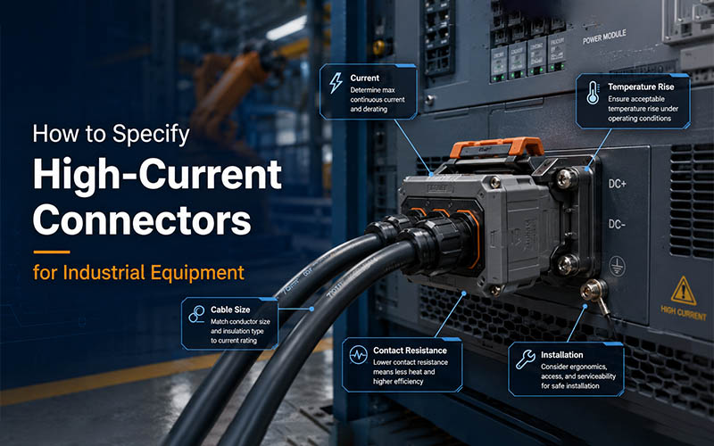
specify high-current connectors for industrial equipment

Industrial power connections are moving beyond permanently bolted busbars and screw-terminal blocks. Pluggable interfaces can shorten assembly time, simplify maintenance, and support modular equipment—but only when current, cable size, temperature rise, contact resistance, vibration, and installation conditions are evaluated together.

To specify a high-current connector, define the continuous and peak current, system voltage, conductor size, permitted temperature rise, contact resistance, environmental exposure, vibration level, termination method, mating frequency, and maintenance requirements. Final selection should be validated under actual equipment conditions.

The highest ampere value in a catalog is not automatically the best choice. A technically sound selection matches the complete electrical, thermal, mechanical, and service environment of the machine.


Why Industrial Power Connection Design Is Changing

Traditional high-power equipment commonly uses bolted busbars, cable lugs, or screw-terminal blocks. These methods remain suitable for many fixed installations, but they may require tools, controlled tightening torque, sufficient working space, and trained technicians.

They can also make module replacement slower. When an inverter, motor controller, battery module, power supply, heater, or distribution unit must be removed, technicians may need to isolate the system, remove covers, release multiple fasteners, and verify tightening torque during reassembly.

Modern industrial equipment is increasingly modular. Machine builders want components that can be assembled, replaced, and serviced with less downtime. This is driving greater use of pluggable power interfaces in applications ranging from approximately 20A to 500A DC.

However, converting a bolted connection into a plug-and-socket interface does not remove engineering risk. It changes where that risk must be controlled.

The connector now needs to maintain:

  • low and stable electrical resistance;
  • acceptable thermal performance;
  • secure mechanical engagement;
  • suitable protection against dust and moisture;
  • resistance to shock, vibration, and temperature cycling;
  • repeatable cable termination;
  • safe installation and maintenance procedures.

A pluggable solution therefore should be selected as part of the equipment architecture—not as a catalog accessory added near the end of the project.

Start with the Actual Electrical Load

The first task is to define how the equipment really operates.

A useful specification should distinguish between:

  • continuous operating current;
  • temporary overload current;
  • startup or inrush current;
  • regenerative or reverse current;
  • duty cycle;
  • system voltage;
  • expected ambient temperature;
  • allowable voltage drop.

A machine that draws 250A continuously creates a different thermal condition from one that reaches 250A for only a few seconds. Likewise, an interface installed in a ventilated electrical cabinet behaves differently from the same interface placed beside a motor, heater, converter, or enclosed battery module.

1. Continuous Current

Continuous current determines the long-term thermal load on the contact system, terminal, cable, and surrounding enclosure.

The published rating should be treated as a starting point. Engineers should confirm the conditions under which it was established, including:

  • ambient temperature;
  • conductor cross-section;
  • number of energized contacts;
  • enclosure condition;
  • permitted temperature rise;
  • test method.

2. Peak and Transient Current

Peak current can occur during motor starting, capacitor charging, welding cycles, hydraulic pump activation, inverter operation, or battery discharge.

A short peak may not heat the complete cable significantly, but it can still create local stress at the contact interface. The connector manufacturer should therefore understand both the magnitude and duration of the peak.

3. Voltage and Insulation Requirements

Voltage selection affects more than the printed voltage rating. The design must also consider:

  • clearance and creepage distance;
  • insulation material;
  • pollution degree;
  • altitude;
  • overvoltage category;
  • touch protection;
  • grounding requirements;
  • whether connection or disconnection could occur while energized.

High current and high voltage are separate design variables. A product with sufficient ampere capacity may still be unsuitable for the required insulation environment.


Match the Cable Size to the Current and Terminal

Cable size cannot be selected independently from the connector.

The conductor must carry the required load without excessive voltage drop or thermal stress, while the terminal barrel must be designed for the same conductor class and cross-section.

Important cable variables include:

  • copper or aluminum conductor;
  • conductor cross-sectional area;
  • AWG or metric size;
  • strand class and flexibility;
  • insulation diameter;
  • insulation temperature rating;
  • cable bending radius;
  • shielded or unshielded construction.

A terminal designed for 50 mm² cable should not be assumed to perform correctly with a smaller or larger conductor merely because it can be physically inserted.

Incorrect conductor-to-terminal matching may cause:

  • incomplete conductor compression;
  • excessive voids inside the crimp;
  • broken strands;
  • low pull-out strength;
  • unstable resistance;
  • localized overheating;
  • poor sealing at the cable entry.

1. Cable Size Does Not Determine Current Alone

A larger conductor generally offers lower resistance, but safe current capacity still depends on insulation temperature, bundling, ventilation, cable length, installation method, and ambient conditions.

The complete current path should be reviewed—from the source and cable to the terminal, contact interface, panel inlet, busbar, and load.

2. Consider Routing and Mechanical Load

Large power cables can apply substantial force to an interface.

During layout review, check:

  • cable exit direction;
  • minimum bending radius;
  • unsupported cable weight;
  • strain relief;
  • torsional load;
  • side load on the receptacle;
  • available installation space.

An electrically correct interface can still fail prematurely if the cable continuously pulls or twists the mating pair.

specify high-current connectors for industrial equipment


Evaluate Temperature Rise, Not Just Rated Current

Current creates heat wherever electrical resistance exists.

The basic relationship is:

Power loss = Current² × Resistance

This means that a small increase in resistance becomes much more important as current rises.

For example, doubling current increases resistive heat by a factor of four when resistance remains unchanged. This is why milliohm-level changes matter in high-power equipment.

1. What Causes Temperature Rise?

Temperature rise at an interface can be affected by:

  • contact resistance;
  • conductor resistance;
  • terminal material;
  • contact geometry;
  • normal contact force;
  • plating condition;
  • crimp quality;
  • ambient temperature;
  • enclosure airflow;
  • adjacent heat sources;
  • contamination or corrosion;
  • cable size.

Temperature-rise testing and current-temperature derating are recognized methods for assessing connector current-carrying capacity. The selected interface should be verified at the expected ambient temperature rather than assumed safe from a room-temperature catalog value.

2. Why Derating Is Necessary

A connector tested in open air at 25°C may operate differently inside a sealed cabinet at 55°C.

As ambient temperature rises, less thermal margin remains before the terminal, housing, seal, or cable insulation approaches its allowable limit.

Derating may also be necessary when:

  • several power contacts are energized together;
  • connectors are installed close to each other;
  • airflow is restricted;
  • cable bundles retain heat;
  • the equipment operates continuously;
  • contamination affects heat dissipation.

3. Validate the Complete Assembly

Temperature testing should include the actual or representative:

  • connector pair;
  • cable cross-section;
  • crimp or termination process;
  • cable length;
  • panel mounting arrangement;
  • enclosure environment;
  • current profile.

Testing only an isolated contact may not reveal the real thermal behavior of the final assembly.


Control Contact Resistance Throughout Service Life

Low initial resistance is important, but stable resistance over time is more important.

The contact system should maintain sufficient normal force and a clean conductive interface after exposure to vibration, mating cycles, temperature changes, and environmental contamination.

1. Main Sources of Resistance Growth

Resistance may increase because of:

  • insufficient contact pressure;
  • contact wear;
  • fretting corrosion;
  • surface oxidation;
  • contamination;
  • damaged plating;
  • loose termination;
  • conductor strand movement;
  • thermal expansion and contraction;
  • improper mating.

As resistance increases, the interface generates more heat. Additional heat can accelerate oxidation, stress relaxation, housing deformation, or insulation aging, creating a self-reinforcing failure process.

2. Contact Material and Plating

The correct contact material and finish depend on current density, mating frequency, environment, and cost requirements.

Common considerations include:

  • copper-alloy conductivity;
  • spring performance;
  • silver, tin, or gold contact finish;
  • plating thickness;
  • wear resistance;
  • corrosion protection;
  • compatibility between mating surfaces.

The lowest-cost plating is not always the lowest lifecycle-cost solution. It should be selected according to the actual operating environment and expected service life.

3. Measure Resistance Correctly

Contact resistance should be measured using a defined test method and stable fixture conditions. Measurements should be compared:

  • before environmental testing;
  • after vibration;
  • after thermal cycling;
  • after mating durability;
  • after corrosion or humidity exposure.

The change in resistance often reveals more about long-term reliability than the initial value alone.


Account for Vibration and Thermal Cycling

Industrial equipment may experience continuous vibration from motors, pumps, compressors, fans, mobile platforms, machining processes, or vehicle movement.

Vibration can create small relative movements at the contact interface. Over time, this may cause fretting, plating wear, resistance drift, or loosening.

Thermal cycling creates a different mechanical load. Metals, plastics, seals, conductors, and housings expand and contract at different rates. Repeated cycles can affect:

  • contact force;
  • terminal retention;
  • crimp stability;
  • sealing;
  • fastener torque;
  • housing geometry.

Questions to Ask During Selection

  1. Is the interface intended for stationary or mobile equipment?
  2. What vibration frequency and acceleration are expected?
  3. Will the cable move independently from the enclosure?
  4. Is a secondary locking feature required?
  5. Can the connection be inspected visually?
  6. Has resistance been measured after vibration testing?
  7. Will the equipment experience rapid hot-to-cold transitions?

A high current rating does not compensate for insufficient mechanical retention.


Choose the Right Installation Method

The best connection method depends on how the equipment is manufactured, installed, and serviced.

Installation methodMain advantagesMain considerations
Bolted busbarHigh current capacity and compact fixed jointRequires torque control, tools, access, and inspection
Cable lug and studFamiliar and widely availableAssembly time and loosening risk must be managed
Screw terminalFlexible field wiringTorque and conductor preparation affect reliability
Crimped pluggable connectorFast assembly, repeatable termination, easier replacementRequires correct tooling and process control
Push-in or spring connectionFast wiring and reduced retighteningMust match conductor size and application current
Panel-mount plug and receptacleSupports modular equipment and service accessRequires correct panel strength, sealing, and cable routing

1. Crimp Termination

A controlled crimp creates a gas-tight mechanical and electrical joint without solder.

Key controls include:

  • correct terminal and wire combination;
  • specified crimp height;
  • conductor position;
  • bellmouth condition;
  • insulation support;
  • pull-force testing;
  • cross-section analysis;
  • calibrated tooling.

FPIC’s internal crimping requirements emphasize conductor crimp height, insulation support, visible conductor position, pull-force testing, and cross-section inspection as core quality controls.

2. Panel-Mount Interfaces

Panel-mounted receptacles can simplify equipment modularity, but the panel design must support:

  • mounting loads;
  • mating and unmating forces;
  • vibration;
  • sealing surfaces;
  • busbar or cable attachment;
  • service access.

The connector should not be expected to compensate for a weak mounting panel or unsupported cable.


Define Maintainability Before Freezing the Design

Maintainability should be a design requirement, not an afterthought.

Ask how technicians will isolate, access, disconnect, inspect, replace, and reconnect the component.

A pluggable system may reduce:

  • equipment replacement time;
  • field wiring errors;
  • dependence on torque tools;
  • access space requirements;
  • production assembly time;
  • machine downtime.

However, these benefits depend on correct interface design.

1. Useful Service Features

Depending on the application, useful features may include:

  • clear polarity or position coding;
  • mechanical keying;
  • visible locking confirmation;
  • touch-safe contacts;
  • secondary locking;
  • tool-free release;
  • replaceable cable assemblies;
  • accessible test points;
  • defined mating sequence.

2. Prevent Disconnection Under Load

Many industrial connectors are not intended to interrupt operating current.

The equipment design should clearly define:

  • isolation procedure;
  • interlock requirements;
  • lockout/tagout method;
  • whether an auxiliary contact is needed;
  • whether the connector can be accessed while energized.

A serviceable interface is not automatically a switching device.


Specify Environmental Protection Correctly

Industrial equipment may operate in clean indoor cabinets, dusty production areas, outdoor machinery, washdown zones, or corrosive environments.

The specification should define:

  • dust and water exposure;
  • IP requirement in mated and unmated condition;
  • operating temperature;
  • humidity;
  • salt spray or chemical exposure;
  • UV exposure;
  • altitude;
  • shock and impact;
  • flammability requirement.

Do not select an IP rating without checking when it applies. Some products achieve the stated protection only when fully mated and correctly assembled with the specified seals and cable diameter.

Use a Complete Engineering Specification

A practical RFQ should provide more than a desired ampere value.

Specification itemInformation to provide
ApplicationMachine, inverter, motor, battery, heater, power supply, distribution unit
VoltageNominal, maximum, AC or DC
CurrentContinuous, peak, duration, and duty cycle
CableMaterial, cross-section, strand class, outer diameter
TemperatureAmbient, internal cabinet, cable and terminal limits
EnvironmentIndoor, outdoor, dust, water, oil, chemicals, salt
Mechanical loadVibration, shock, cable movement, mating cycles
InstallationPanel, cable-to-cable, busbar, PCB, blind mate
TerminationCrimp, screw, stud, busbar, push-in
SafetyTouch protection, coding, grounding, interlock
MaintenanceReplacement frequency, tool access, service time
ComplianceRequired IEC, UL, EN, railway, automotive, or customer standards

Providing these details allows a manufacturer to recommend an interface based on the real system rather than simply matching a catalog current rating.


How FPIC Supports Industrial Power Connection Projects

FPIC develops and manufactures connectors, cable assemblies, terminals, and precision components for industrial equipment and high-power applications.

Our support can include:

FPIC’s industrial connector capability includes rugged power, signal, and cable-assembly solutions for equipment that requires stable electrical performance, vibration resistance, environmental protection, and controlled production quality.

Our laboratory and inspection capabilities include temperature-rise testing, contact-resistance measurement, insertion and extraction testing, thermal shock, vibration testing, X-ray inspection, dimensional measurement, and cleanliness inspection.

For qualified custom development projects, FPIC can also provide end-to-end support from product review and tooling through validation and mass-production preparation.

A Practical Selection Workflow

Use the following seven-step process when specifying an industrial power interface:

1. Define the Current Profile

Document continuous current, overload, peak duration, and duty cycle.

2. Confirm Voltage and Safety Requirements

Define insulation, touch protection, grounding, coding, and disconnection rules.

3. Select the Conductor

Match cable size, strand class, insulation rating, and routing requirements.

4. Establish the Thermal Limit

Define maximum ambient temperature and allowable temperature rise.

5. Review Mechanical Conditions

Evaluate vibration, shock, cable load, mating cycles, and locking requirements.

6. Choose the Installation Architecture

Compare bolted, screw, crimped, panel-mounted, and pluggable solutions according to production and maintenance needs.

7. Validate the Final Assembly

Test the real cable, termination, connector pair, mounting method, current profile, and environmental conditions.


Frequently Asked Questions

1. Is the catalog current rating enough for connector selection?

No. The rating must be reviewed together with ambient temperature, cable size, enclosure conditions, duty cycle, contact resistance, and allowable temperature rise.

2. Why does cable size affect connector performance?

The conductor size influences resistance, heat generation, crimp quality, voltage drop, cable flexibility, and the terminal design required for reliable termination.

3. What causes an industrial power connector to overheat?

Common causes include excessive current, unstable contact resistance, poor crimping, an undersized conductor, contamination, loose mating, damaged plating, and insufficient heat dissipation.

4. Are pluggable connectors better than bolted busbars?

Not in every application. Pluggable products improve modularity and serviceability, while bolted busbars remain effective for fixed, compact, very-high-current connections. The correct choice depends on operating and maintenance requirements.

5. Should temperature rise be tested in the final equipment?

Yes. Final validation should use a representative cable, termination, mounting arrangement, enclosure, ambient temperature, and electrical load.


Conclusion

A reliable industrial power interface cannot be selected by current rating alone.

The final decision must connect electrical load, conductor size, thermal performance, contact stability, vibration resistance, environmental protection, installation method, and maintenance strategy.

When these factors are evaluated together, pluggable power connectors can help equipment manufacturers shorten assembly time, improve modularity, reduce service effort, and build more reliable industrial systems.

Discuss Your Industrial Power Connection Project

FPIC supports customized connector and cable-assembly development for industrial equipment, high-voltage systems, and high-current power interfaces.

Send us your application requirements, current and voltage ratings, cable specification, drawings, and operating conditions for engineering evaluation.

Email: info@fpiconn.com

Resources

  1. Connector Supplier – How to Specify High-Current Connectors for Industrial Equipment
  2. IEC 60512-5-1 – Current-Carrying Capacity Tests: Temperature Rise
  3. IEC 60512-5-2 – Current-Temperature Derating
  4. IEC 60512-2-1 – Contact Resistance Test Method
  5. TE Connectivity – Heavy-Duty Industrial Connectors
  6. Phoenix Contact – Heavy-Duty Connectors
  7. HARTING – Industrial Rectangular Connectors
  8. Materion – How Much Current Can Safely Run Through a Connector?
  9. KYOCERA AVX – Criteria for Selecting Connectors for Industrial Applications
High-Voltage Connectors for BESS Cabinets

Battery energy storage is moving fast, and the connector conversation is changing with it. In BESS cabinets, buyers are no longer looking only at whether a connector can carry power. They are also paying closer attention to electrical safety, temperature rise, installation speed, serviceability, and system-level risk control.

As BESS projects become larger and more power-dense, connector selection is becoming part of core system design rather than a late-stage component decision.

Why High-Voltage Connector Selection Is Changing in BESS

For many years, connector selection in energy storage projects often focused on a small set of basic questions: voltage class, current rating, and physical fit. That is no longer enough.

Today, BESS cabinet developers need to think about how each connection point behaves in real operating conditions. A connector sits inside a power path that may involve battery modules, busbars, rack interfaces, cabinet-level routing, and maintenance access. In that context, the connector affects much more than electrical continuity.

A high-voltage connector can influence:

  • connection stability under continuous load
  • temperature rise in compact cabinet layouts
  • installation consistency on the production floor
  • protection against polarity or mating mistakes
  • service efficiency during maintenance or replacement
  • long-term reliability in demanding operating environments

That is why the market is shifting from simple part supply toward more integrated thinking around safety, operability, and lifecycle risk.

Safety Comes First in BESS Cabinet Connection Design

In BESS cabinets, a power connection is not just a mechanical joint. It is part of a high-energy system where safety must be designed in from the start.

This is why high-voltage connectors are increasingly evaluated for features such as:

1. Touch-Proof Protection

In cabinet-level power systems, exposed conductive points create avoidable handling risk. A touch-proof connector structure helps reduce exposure during assembly, maintenance, and replacement.

2. Polarity Control and Mechanical Keying

As systems become more modular, polarity clarity and anti-misplug design become more important. Mechanical keying can help prevent mating errors and improve installation discipline in large-volume production and field service.ZED

3. Secure Mating and Locking

A connector should not only mate electrically. It should also provide a reliable mechanical connection that helps maintain stable contact under vibration, cable movement, and long-term use.

4. System-Level Compliance Readiness

For customers developing certified battery equipment, component selection increasingly needs to align with safety and compliance expectations early in the design process.

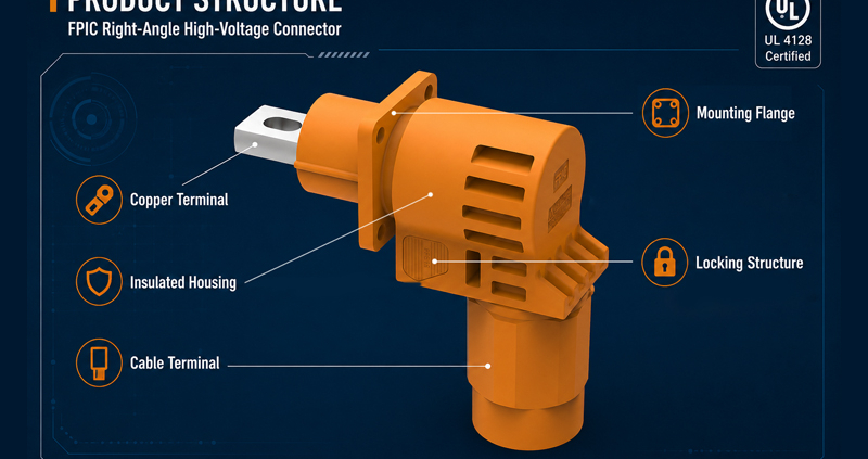
High-current connector used in BESS cabinet energy storage system

Current Rating Is Important, but It Is Not the Whole Story

Current rating is still a critical starting point, but it should never be treated as the only selection criterion.

In BESS cabinet design, the real question is not simply “What current is printed in the catalog?” It is “Can this connector carry the required current stably, safely, and repeatedly in the actual cabinet environment?”

That means engineers and sourcing teams should look at current rating together with:

  • contact resistance stability
  • conductor matching
  • termination quality
  • temperature rise performance
  • insulation coordination
  • practical routing constraints
  • installation and maintenance conditions

A connector that looks sufficient on paper may still create heat, service complexity, or reliability risk if the rest of the interface design is not well matched.

Installation Efficiency Is Becoming a Competitive Advantage

As BESS cabinet production scales, installation logic matters more.

A connector that supports clearer mating, easier routing, faster assembly, and reduced torque-based work can improve both productivity and consistency. In high-volume cabinet production, even small improvements in connection time can create meaningful gains in labor efficiency and quality control.

Installation-friendly connector design can also help reduce:

  • assembly errors
  • cable strain
  • rework time
  • maintenance complexity later in the project lifecycle

This is one reason why the market is paying closer attention to connector structure, not just electrical data.

What Engineers Should Evaluate in a BESS High-Voltage Connector

When selecting a high-voltage connector for BESS cabinets, a more complete evaluation usually includes the following questions:

1. Is the voltage platform right for the target system?

The connector should match the actual architecture, whether the project is centered on 1000V, 1500V, or higher-voltage development.

2. Is the current rating suitable for continuous system conditions?

The connector should fit the expected current path without creating unnecessary thermal pressure or overdesign cost.

3. Does the structure improve safety?

Touch-proof features, polarity control, and reliable locking all contribute to safer installation and operation.

4. Does the connector fit cabinet integration needs?

Panel mounting, cable exit direction, keying, and space use all affect cabinet design quality.

5. Will service and replacement be practical later?

A connector should not make maintenance harder than it needs to be.

Where FPIC’s 2000V 450A Connector Fits

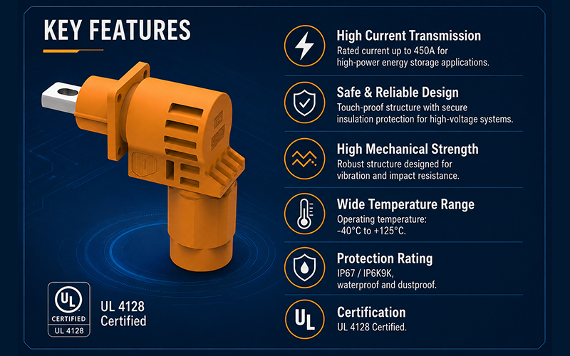
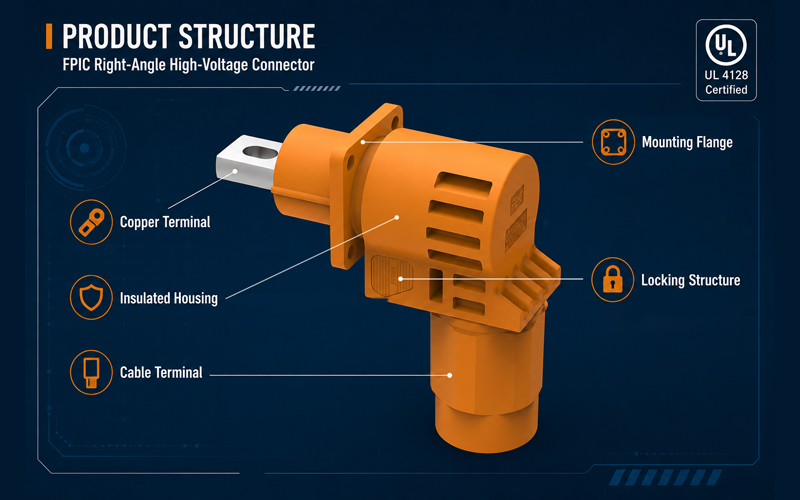
For higher-power BESS cabinet applications, FPIC’s 2000V 450A energy storage connector is positioned for customers who need a stronger high-voltage, high-current interconnection solution with a safety-oriented structure and system-integration logic.

This connector direction is particularly relevant where designers are looking for:

  • higher-voltage platform support
  • cabinet-level high-current interfaces
  • safer handling through touch-proof structure
  • clearer polarity and keying control
  • more flexible routing and installation

FPIC’s energy storage connector development already includes features such as touch-proof design, 360-degree rotating plug structure, multiple connection methods, and different installation keying options, which directly support the practical needs of BESS cabinet integration.

For customers moving beyond basic current transfer and toward safer, more maintainable cabinet power architecture, this matters.

Why 2000V 450A Matters in the Current Market Context

As the market shifts toward larger and more demanding storage projects, high-power connector platforms become more relevant for two reasons.

First, they help support the design of higher-density cabinet systems with more demanding power interfaces.

Second, they show that connector suppliers are not only following the storage trend, but also investing in the next layer of interconnection capability.

FPIC’s 2000V 450A series is part of that move. It is not positioned as a generic connector. It is better understood as a high-power energy storage interconnection solution for battery-system applications where safety, current path stability, and system integration all matter.

FPIC Energy Storage Connector Capability

FPIC supports energy storage connector development across multiple platform levels, including 1000V, 1500V, and higher-voltage product directions for battery-system applications.

Our energy storage connector portfolio is built around real application needs such as:

  • battery module interfaces
  • battery rack and cabinet connections
  • high-current DC distribution paths
  • safer installation and service access

For customers developing BESS cabinets, battery packs, or related high-voltage storage equipment, FPIC can support product communication and connector matching based on application requirements.

High-Voltage Connectors for BESS Cabinets

Conclusion

The role of high-voltage connectors in BESS cabinets is getting bigger, not smaller. As storage systems scale, connector selection is increasingly tied to safety, temperature control, installation efficiency, and long-term operating risk.

That is why the market is moving beyond simple part supply toward more integrated interconnection thinking.

For projects that need a stronger high-power solution, FPIC’s 2000V 450A energy storage connector provides a relevant option to support safer and more capable BESS cabinet design.

Contact FPIC

Looking for a high-voltage connector solution for BESS cabinets, battery racks, or high-current storage systems?

Contact FPIC to discuss your project requirements and connector platform options.

Email: info@fpiconn.com
Website: fpiconn.com

Resources

Reuters. Lithium producers bet on battery storage as demand shifts beyond EVs. June 24, 2026.
Molex. Designing Battery Energy Storage Systems (BESS).
Molex. Battery Pack Connections for Energy Storage Systems.
Molex. BESS Inverter Connectors.
Phoenix Contact. Connectors for Energy Storage Systems.
TE Connectivity. Battery Energy Storage Systems (BESS).
TE Connectivity. HPC 350A Connector for BESS Applications.

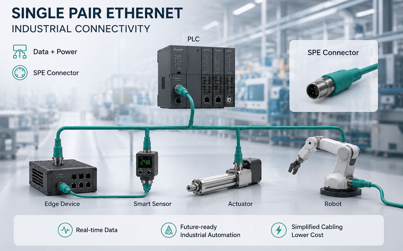
Single Pair Ethernet Connectors Overview

Industrial automation networks are entering a new phase of connectivity.

For decades, factory communication systems have relied on:

  • Fieldbus networks
  • Industrial Ethernet
  • M8 and M12 connectors
  • RJ45 interfaces
  • Multi-pair communication cables

Today, Single Pair Ethernet (SPE) is emerging as one of the most important technologies supporting Industry 4.0, IIoT, and smart manufacturing initiatives.

While SPE has been discussed for several years, 2026 is expected to be a significant milestone as more industrial equipment manufacturers move from pilot projects to commercial deployment.

For engineers, OEM buyers, and system integrators, understanding upcoming SPE connector trends can help guide future product and infrastructure decisions.

Single Pair Ethernet Connectors Overview


Why SPE Is Gaining Momentum

Industrial networks continue to evolve toward greater connectivity.

Factories now require:

  • more sensors
  • more data collection
  • more edge devices
  • more intelligent actuators

Traditional Ethernet remains effective, but many field-level devices do not require the size and complexity of four-pair Ethernet infrastructure.

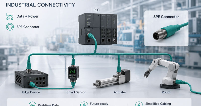
Single Pair Ethernet offers:

  • reduced cable size
  • lighter harnesses
  • simplified installation
  • Ethernet-based communication down to the sensor level

This makes SPE highly attractive for next-generation automation architectures.


Trend #1: Increasing Adoption of IEC 63171 Connector Standards

One of the biggest developments to watch in 2026 is the growing acceptance of IEC 63171 connector standards.

These standards define connector interfaces for SPE applications.

Common variants include:

  • IEC 63171-2
  • IEC 63171-5
  • IEC 63171-6

As more automation suppliers adopt standardized interfaces, interoperability across equipment platforms is expected to improve.

For buyers, connector standard compatibility will become an increasingly important procurement criterion.


Trend #2: Expansion of SPE in Smart Sensors and Actuators

Many industrial sensors currently use:

  • discrete I/O
  • fieldbus interfaces
  • proprietary communication methods

SPE enables direct Ethernet connectivity to field devices.

Benefits include:

  • simplified architectures
  • real-time diagnostics
  • easier device integration
  • reduced gateway requirements

By 2026, more sensor and actuator manufacturers are expected to release SPE-enabled products.


Trend #3: Growth of Power over Data Line (PoDL)

Power over Data Line (PoDL) remains one of the most compelling SPE features.

PoDL allows:

  • data transmission
  • device power

through the same twisted pair.

Potential advantages include:

  • fewer cables
  • reduced installation costs
  • smaller harnesses
  • simplified device deployment

As SPE ecosystems mature, PoDL adoption is expected to accelerate across industrial automation markets.


Trend #4: Smaller and More Compact Industrial Devices

Machine builders continue to pursue:

  • smaller equipment footprints
  • higher device density
  • reduced cabinet space

SPE connectors support these goals through:

  • compact connector designs
  • reduced cable diameter
  • lighter cable assemblies

This trend is particularly important in:

  • robotics
  • machine vision
  • semiconductor equipment
  • compact automation cells

Connector miniaturization will remain a major development focus in 2026.


Trend #5: Stronger Focus on EMC Performance

As industrial networks become more data-driven, communication reliability becomes increasingly critical.

Industrial environments contain significant sources of electromagnetic interference:

  • servo drives
  • VFDs
  • motors
  • switching power supplies

Although SPE cables are smaller, EMC challenges remain.

Future SPE connector development will likely emphasize:

  • improved shielding
  • lower transfer impedance
  • optimized grounding
  • enhanced connector shielding continuity

EMC performance will continue to be a key differentiator among suppliers.


Trend #6: More SPE Solutions for Robotics

Robotic systems require communication solutions that can withstand:

  • continuous flexing
  • torsion
  • vibration

As robots become more connected, SPE presents an opportunity to simplify communication architectures.

However, robotic SPE cable assemblies must still address:

  • dynamic motion
  • shielding durability
  • flex life requirements

2026 may see a broader range of SPE products specifically designed for robotic applications.


Trend #7: Integration with Industry 4.0 Architectures

Industry 4.0 initiatives emphasize:

  • unified communication
  • real-time data access
  • device interoperability

SPE aligns closely with these goals.

Benefits include:

  • end-to-end Ethernet connectivity
  • simplified networking
  • easier data collection
  • scalable architectures

Many manufacturers view SPE as a foundational technology for future smart factories.


Trend #8: Growing Demand for Hybrid Connectivity Solutions

The transition to SPE will not happen overnight.

Many facilities will operate mixed environments including:

  • traditional Ethernet
  • fieldbus networks
  • SPE networks

As a result, demand is growing for:

  • SPE-to-Ethernet adapters
  • hybrid cable assemblies
  • migration-friendly connectivity solutions

Suppliers that support both legacy and emerging standards may have a competitive advantage.


Trend #9: Higher Expectations for IP Protection

Industrial users continue to demand robust environmental protection.

Common requirements include:

IP67

Factory automation equipment.

IP68

Harsh industrial environments.

IP69K

Washdown applications.

Future SPE connectors will need to maintain industrial-grade sealing despite smaller form factors.


Trend #10: Supplier Qualification Will Become More Important

As SPE adoption grows, buyers will increasingly evaluate suppliers based on:

  • connector standard compliance
  • EMC performance
  • environmental testing
  • manufacturing quality
  • application engineering support

Selecting the right connectivity partner may become as important as selecting the connector itself.


Challenges That Still Need Attention

Although SPE offers significant advantages, several challenges remain.

Standard Fragmentation

Multiple connector standards continue to coexist.

Ecosystem Maturity

Some industrial markets are still in the early adoption phase.

Infrastructure Transition

Existing Ethernet systems remain deeply established.

Education and Training

Many engineers are still learning SPE design principles.

These factors will influence adoption rates over the coming years.


Questions Buyers Should Ask in 2026

Before selecting SPE connector solutions, buyers should ask:

  • Which IEC 63171 standard is supported?
  • Is PoDL available?
  • What EMC testing has been completed?
  • What IP protection level is achieved?
  • Is the connector suitable for robotics or drag-chain applications?
  • What interoperability testing has been performed?
  • How does the supplier support future scalability?

Typical Applications Expected to Grow

SPE connectors are expected to expand across:

  • Smart sensors
  • Intelligent actuators
  • Industrial IoT devices
  • Edge computing equipment
  • Robotics
  • Machine vision systems
  • Process automation
  • Smart manufacturing platforms

How FPIC Supports Emerging SPE Connectivity Needs

FPIC develops advanced industrial connectivity solutions including:

  • SPE cable assemblies
  • Industrial Ethernet harnesses
  • M8 and M12 communication cables
  • Shielded data cable assemblies
  • Robotic communication harnesses
  • Custom overmolded connector solutions

Our engineering team helps customers evaluate emerging connectivity technologies while maintaining compatibility with current industrial infrastructure.


Final Thoughts

Single Pair Ethernet connectors are moving from concept to practical deployment.

In 2026, key developments are expected around:

  • IEC 63171 standard adoption
  • PoDL expansion
  • connector miniaturization
  • robotics integration
  • Industry 4.0 implementation
  • EMC optimization

For OEMs and industrial buyers, now is the time to understand SPE technologies and prepare for the next generation of industrial networking.

Organizations that evaluate SPE early may gain advantages in system simplification, scalability, and future connectivity readiness.


FAQ

What is a Single Pair Ethernet connector?

An SPE connector is a connector designed to transmit Ethernet communication through a single twisted pair of conductors.

What is PoDL?

Power over Data Line (PoDL) enables both power and data transmission over the same SPE cable.

Will SPE replace Industrial Ethernet?

Not immediately. SPE is expected to complement existing Ethernet infrastructure, particularly at the device level.

Which SPE connector standards are most important?

IEC 63171-2, IEC 63171-5, and IEC 63171-6 are among the most widely discussed industrial SPE connector standards.

Why is SPE important for Industry 4.0?

SPE enables direct Ethernet connectivity to sensors and actuators, supporting unified and scalable industrial communication architectures.


Planning for Next-Generation Industrial Connectivity?

FPIC provides custom SPE cable assemblies, Industrial Ethernet harnesses, M8/M12 connectivity solutions, and engineering support for automation, robotics, and Industrial IoT applications.

Contact us to discuss your future Single Pair Ethernet connectivity requirements.


Resources

  1. IEC 63171 Series – Single Pair Ethernet Connector Standards
  2. IEEE 802.3cg – 10BASE-T1L and 10BASE-T1S Standards
  3. PROFIBUS & PROFINET International (PI) SPE Resources
  4. ODVA Single Pair Ethernet Guidance
  5. Phoenix Contact and HARTING SPE Technology Documentation

Source References: IEC 63171, IEEE 802.3cg, PI, ODVA, Phoenix Contact, HARTING SPE technical resources.

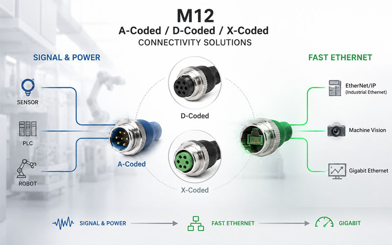
M12 A-Coded vs D-Coded vs X-Coded Overview

M12 Connectors have become one of the most widely used connectivity solutions in industrial automation.

You’ll find them in:

  • PLC systems
  • Industrial Ethernet networks
  • Sensors and actuators
  • Machine vision equipment
  • Robotics
  • Servo drives
  • IIoT devices

However, one common misconception is that all M12 connectors are interchangeable.

In reality, X-coded, D-coded, and A-coded M12 connectors are designed for different purposes, and selecting the wrong type can lead to communication limitations, compatibility issues, or unnecessary costs.

This article explains the key differences and helps industrial buyers choose the right M12 connector for their application.

M12 A-Coded vs D-Coded vs X-Coded Overview


Understanding M12 Connector Coding

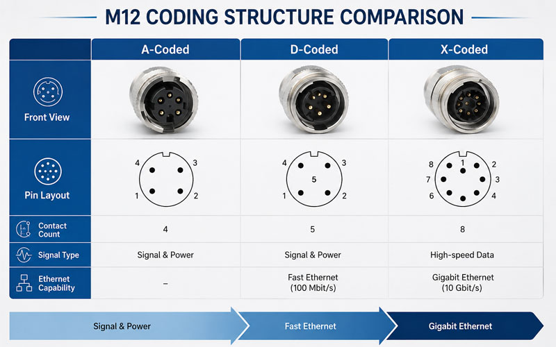
The coding of an M12 connector determines:

  • pin arrangement
  • electrical isolation
  • supported protocols
  • data transmission capability
  • application suitability

The coding prevents incompatible connectors from being accidentally mated.

Among the various M12 coding types, A-coded, D-coded, and X-coded are the most commonly encountered in industrial automation.

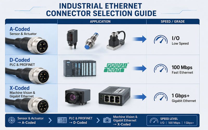
M12 Coding Structure Comparison


What Is an A-Coded M12 Connector?

A-coded connectors were originally developed for industrial sensors and actuators.

They are the most widely used M12 connector type.

Typical Applications

  • Proximity sensors
  • Photoelectric sensors
  • Solenoid valves
  • I/O modules
  • Power distribution
  • Basic field devices

Common Pin Counts

  • 3-pin
  • 4-pin
  • 5-pin
  • 8-pin
  • 12-pin

Main Function

A-coded connectors primarily carry:

  • power signals
  • discrete I/O signals
  • analog signals

They are generally not intended for high-speed Ethernet communication.


What Is a D-Coded M12 Connector?

D-coded connectors were developed specifically for Industrial Ethernet applications.

Typical Applications

  • PROFINET
  • EtherNet/IP
  • Industrial switches
  • PLC communication
  • Machine networking

Ethernet Capability

D-coded connectors typically support:

  • Fast Ethernet
  • 100 Mbps communication

Pin Configuration

D-coded connectors use:

  • 4 contacts
  • 2 twisted pairs

This configuration is optimized for industrial network communication.


What Is an X-Coded M12 Connector?

X-coded connectors were introduced to support higher Ethernet bandwidth requirements.

As Industry 4.0 and machine vision applications expanded, Fast Ethernet became insufficient for many systems.

Typical Applications

  • Gigabit Ethernet
  • Machine vision
  • Industrial cameras
  • High-speed data acquisition
  • Smart manufacturing equipment

Ethernet Capability

X-coded connectors support:

  • 1 Gbps Ethernet
  • 10 Gbps Ethernet (depending on system design)

Pin Configuration

X-coded connectors use:

  • 8 contacts
  • 4 twisted pairs

Internal shielding separates the pairs to improve EMC performance and reduce crosstalk.


Quick Comparison

FeatureA-CodedD-CodedX-Coded
Primary UseSensors & PowerIndustrial EthernetHigh-Speed Ethernet
Typical SpeedSignal/Power100 Mbps1 Gbps+
Contact Count3–12 Pins4 Pins8 Pins
Ethernet SupportLimitedYesYes
Shielding RequirementLow–MediumHighVery High
Common ApplicationsSensors, I/OPLC NetworksVision & Data Systems

Why X-Coded Is Becoming More Popular

Several trends are driving adoption of X-coded connectors:

Machine Vision Systems

Industrial cameras generate large amounts of data.

Gigabit Ethernet is often required.

Industry 4.0

Modern smart factories rely on:

  • real-time monitoring
  • edge computing
  • high-speed communication

Future-Proofing

Many OEMs choose X-coded solutions today to avoid future bandwidth limitations.


Why D-Coded Remains Relevant

Although X-coded connectors offer higher speeds, D-coded connectors remain widely used.

Reasons include:

  • lower cost
  • established PROFINET infrastructure
  • sufficient bandwidth for many automation systems
  • simpler network architectures

Many PLC and I/O networks do not require Gigabit Ethernet.


Why A-Coded Connectors Are Often Misunderstood

A common mistake is assuming that all M12 connectors can be used for Ethernet.

Many A-coded connectors physically resemble D-coded or X-coded versions.

However:

  • contact layouts differ
  • shielding requirements differ
  • communication capability differs

An A-coded connector should generally be viewed as a sensor, actuator, or power connector rather than an Ethernet connector.


Shielding Considerations

As data rates increase, EMC performance becomes more critical.

A-Coded

Typically used for power and signals.

Shielding requirements vary by application.

D-Coded

Requires shielded twisted pairs and proper grounding.

X-Coded

Requires:

  • advanced shielding
  • pair separation
  • 360° shield termination
  • controlled impedance design

High-speed Ethernet performance depends heavily on shielding quality.


IP Ratings and Environmental Protection

All three connector types can be supplied with:

  • IP67 protection
  • IP68 protection
  • IP69K protection

The coding itself does not determine environmental sealing.

Protection level depends on connector design and assembly quality.


Connector Selection by Application

Choose A-Coded When:

✓ Connecting sensors

✓ Connecting actuators

✓ Transmitting power

✓ Handling standard I/O signals


Choose D-Coded When:

✓ Deploying PROFINET

✓ Using Fast Ethernet networks

✓ Connecting PLCs and switches

✓ Bandwidth requirements remain below Gigabit levels


Choose X-Coded When:

✓ Using Gigabit Ethernet

✓ Supporting machine vision systems

✓ Future-proofing network infrastructure

✓ Managing high-data applications

Industrial Ethernet Connector Selection Guide


Common Buyer Mistakes

Selecting Based Only on Connector Appearance

M12 coding determines functionality.

Appearance alone can be misleading.

Overlooking Bandwidth Requirements

Future communication needs should be considered.

Ignoring Shielding Quality

High-speed communication requires robust EMC design.

Using A-Coded Connectors for Ethernet Applications

This can create communication failures and compatibility issues.

Focusing Only on IP Rating

Electrical performance is just as important as environmental protection.


Questions Buyers Should Ask Suppliers

Before selecting an M12 connector solution, ask:

  • What coding is used?
  • What Ethernet speed is supported?
  • Is the connector shielded?
  • Is 360° shield termination available?
  • What IP rating is achieved?
  • Is the assembly suitable for drag-chain applications?
  • Has EMC validation been completed?

Typical Applications

A-Coded

  • Sensors
  • Actuators
  • Field I/O

D-Coded

  • PROFINET
  • EtherNet/IP
  • Industrial networking

X-Coded

  • Machine vision
  • Industrial cameras
  • Gigabit Ethernet
  • Smart manufacturing

How FPIC Supports M12 Connectivity Solutions

FPIC provides custom industrial connectivity solutions including:

  • M12 A-coded cable assemblies
  • M12 D-coded Ethernet harnesses
  • M12 X-coded Gigabit Ethernet assemblies
  • Industrial Ethernet cable solutions
  • Drag-chain communication cables
  • Custom overmolded cable assemblies

Our engineering team helps customers select the most suitable connector architecture based on network performance, EMC requirements, and environmental conditions.


Final Thoughts

Choosing between A-coded, D-coded, and X-coded M12 connectors depends on the application.

While A-coded connectors remain ideal for sensors and power distribution, D-coded and X-coded connectors are purpose-built for Industrial Ethernet.

For modern automation systems, selecting the correct coding ensures:

  • network reliability
  • EMC performance
  • future scalability
  • long-term system compatibility

Understanding these differences helps buyers avoid costly design mistakes and improve industrial network performance.


FAQ

Can A-coded M12 connectors be used for Ethernet?

Generally no. A-coded connectors are primarily designed for sensors, actuators, and power transmission.

What is the difference between D-coded and X-coded M12 connectors?

D-coded connectors typically support Fast Ethernet (100 Mbps), while X-coded connectors support Gigabit Ethernet and higher-speed communication.

Which M12 connector is used for PROFINET?

D-coded connectors are commonly used for PROFINET networks, although X-coded versions are increasingly adopted for higher bandwidth applications.

Is X-coded better than D-coded?

Not necessarily. X-coded offers higher bandwidth, but D-coded may be more cost-effective for applications that only require 100 Mbps communication.

Do all M12 connector types support IP67?

Yes. A-coded, D-coded, and X-coded connectors can all be designed to meet IP67 or higher protection ratings.


Looking for Custom M12 Cable Assemblies?

FPIC provides M12 A-coded, D-coded, and X-coded cable assemblies for sensors, Industrial Ethernet, machine vision, robotics, and smart factory applications.

Contact us to discuss your M12 connectivity requirements.


Resources
IEC 61076-2-101 – M12 Connector Standards
IEC 61076-2-109 – M12 X-Coded Connector Standards
PROFINET Installation Guidelines
ODVA EtherNet/IP Infrastructure Guidance
Phoenix Contact Industrial Ethernet Connectivity Documentation
Source References: IEC 61076 Series, PROFIBUS & PROFINET International (PI), ODVA, Phoenix Contact Industrial Connectivity Resources.

Low-Voltage Connector Application

Low-voltage automotive connectors are widely used across vehicle systems such as lighting, seating, and body electronics. Although these applications typically operate below 60V, their reliability requirements are just as critical as high-voltage systems.

Failures in low-voltage connectors can lead to malfunctioning lights, seat control issues, or body system errors—impacting both user experience and vehicle quality perception.

This article explores how to design low-voltage automotive connectors for real-world applications, focusing on performance, reliability, and cost efficiency.

Low-Voltage Connector Application Zones


Why Low-Voltage Connector Design Still Matters

Compared to high-voltage systems, low-voltage connectors may seem less demanding. However, they face their own unique challenges:

  • high connector count across the vehicle
  • frequent mating and service requirements
  • cost sensitivity in high-volume production
  • exposure to vibration, moisture, and temperature

In many cases, low-voltage connectors are used in large quantities, meaning even small design issues can scale into significant reliability or warranty problems.


Typical Application Areas

Lighting Systems

  • headlights and taillights
  • interior lighting
  • signal and indicator systems

Key Requirements:

  • stable electrical contact
  • resistance to moisture and condensation
  • compact design

Seat Systems

  • seat adjustment motors
  • heating and ventilation
  • occupancy sensors

Key Requirements:

  • flexibility under movement
  • resistance to repeated mechanical stress
  • secure locking under vibration

Body Electronics

door modules

window control systems

dashboard and control units

Key Requirements:

signal integrity

space efficiency

ease of assembly


Key Design Considerations

Contact Stability

Even in low-voltage systems, stable contact resistance is essential.

Design should ensure:

  • sufficient and consistent contact force
  • resistance to fretting corrosion
  • long-term electrical stability

Connector Size and Packaging

Space is often limited in lighting modules and seat structures.

Design priorities include:

  • compact housing design
  • optimized pin layout
  • ease of routing within tight spaces

Vibration Resistance

Low-voltage connectors are frequently installed in areas with movement or vibration.

Design strategies:

  • robust locking mechanisms
  • anti-vibration contact design
  • proper harness fixation

Environmental Protection

Depending on installation location, connectors may be exposed to:

  • moisture or condensation
  • dust and contaminants
  • temperature fluctuations

Sealing level should be selected based on installation zone rather than over-specifying protection.


Ease of Assembly

High-volume production requires connectors that are easy to assemble.

Important factors:

  • low insertion force
  • clear locking feedback
  • error-proofing (CPA/TPA if needed)

Common Design Challenges

Cost vs Reliability Trade-Off

Low-voltage connectors are highly cost-sensitive. Overdesign can increase cost, while underdesign can lead to failures.

High Mating Cycle Requirements

Applications such as seats and serviceable components may require connectors to withstand multiple mating cycles.

Mixed Signal and Power Transmission

Some connectors must handle both power and signal circuits, requiring careful design to avoid interference or instability.


Real-World Failure Risks

Even low-voltage connectors can fail due to:

  • fretting corrosion in vibration environments
  • water ingress in poorly protected areas
  • contact resistance drift over time
  • improper assembly or misalignment

These issues are often related to system-level design rather than connector specification alone.


Optimization Strategies

Right-Sizing the Connector

Avoid over-specification. Match connector capability to actual application requirements.

Material and Plating Selection

Choose materials that balance cost and performance:

  • tin plating for cost efficiency
  • gold plating for signal stability (where needed)

Harness Integration

Connector performance depends on the entire harness system:

  • routing design
  • strain relief
  • fixation points

Validation Under Real Conditions

Testing should reflect real use cases:

  • vibration with movement
  • temperature cycling
  • repeated mating cycles

How FPIC Supports Low-Voltage Applications

FPIC supports automotive and industrial customers with:

  • connector and wire harness integration
  • cost-optimized design solutions
  • assembly process optimization
  • validation aligned with real-world conditions

By focusing on both design and manufacturing, low-voltage systems can achieve reliable performance at scale.


Final Thoughts

Low-voltage connectors may not carry high power, but they are critical to overall vehicle functionality and user experience.

A successful design balances:

  • reliability
  • cost efficiency
  • manufacturability
  • real-world performance

Understanding application-specific requirements is key to making the right design decisions.


FAQ

What voltage is considered low voltage in automotive systems?

Typically below 60V DC, including most body electronics and auxiliary systems.

Are low-voltage connectors less critical than high-voltage ones?

No. Failures can still affect safety, comfort, and system functionality.

What is the biggest risk in low-voltage connector design?

Misalignment between connector design and real installation conditions.

When should sealed connectors be used in low-voltage systems?

When exposure to moisture or contaminants is expected.

How can reliability be improved?

Through proper design, material selection, and validation under real conditions.


Optimize Your Low-Voltage Connector Design

If you are developing lighting, seat, or body electronics systems, the right connector design can improve reliability while controlling cost.

FPIC provides customized connector and wire harness solutions tailored to your application needs.

Contact us to discuss your project requirements.


Resources

Reliable connectors and cable assemblies for commercial cleaning equipment

Reliable Connectors for Commercial Cleaning Equipment and Facility Devices

Professional cleaning is no longer limited to manual labor and simple tools. Today, residential, commercial, office, building, and industrial cleaning services often depend on specialized equipment, air treatment devices, floor cleaning machines, aircon cleaning tools, sensors, motors, control boards, and power systems.

For cleaning service providers, equipment reliability directly affects work efficiency, safety, service quality, and customer satisfaction. For equipment manufacturers, stable electrical connections inside each device are essential for long-term performance.

In Singapore, service providers such as Tidyman Cleaning Company offer residential cleaning, commercial cleaning, office cleaning, industrial cleaning, building cleaning, deep cleaning, post-renovation cleaning, move-in and move-out cleaning, and aircon cleaning services. Their broad service scope reflects the growing demand for cleaner, safer, and better-managed indoor environments.

Behind many professional cleaning and facility maintenance devices, connectors and cable assemblies play an important role in power transmission, signal control, and equipment integration.

Why Reliable Connections Matter in Cleaning Equipment

Commercial cleaning equipment may need to operate for long hours, move across different environments, and withstand vibration, moisture, dust, frequent handling, and repeated use.

If internal connectors or cable assemblies are not stable, the equipment may face problems such as:

  • Intermittent power supply
  • Motor control failure
  • Sensor signal interruption
  • Loose internal wiring
  • Overheating risks
  • Reduced equipment service life
  • Higher maintenance cost

For cleaning equipment manufacturers, reliable connectors help improve device performance, reduce field failure, and support consistent operation in demanding service environments.

Reliable connectors and cable assemblies for commercial cleaning equipment

Common Cleaning and Facility Equipment Using Connectors

1. Floor Cleaning Machines

Floor scrubbers, polishers, sweepers, and cleaning machines usually include motors, batteries, control boards, switches, sensors, and display modules. These components require stable cable assemblies and secure connectors to support continuous operation.

Reliable connection design helps reduce downtime and improves the durability of commercial cleaning equipment.

2. Aircon Cleaning and Air Treatment Devices

Aircon cleaning tools, air treatment devices, and ventilation-related equipment may involve pumps, fans, heating modules, sensors, and control systems. Compact wire-to-board connectors and internal wiring harnesses help support stable power and signal transmission.

For devices used in indoor air quality improvement, connection stability is important for both performance and safety.

3. Smart Cleaning Devices

Smart cleaning equipment may include digital controls, sensors, battery modules, charging systems, and communication boards. These applications require compact connectors and customized cable routing to fit limited internal space.

Well-designed cable assemblies can help manufacturers simplify assembly and improve product consistency.

4. Industrial and Building Cleaning Equipment

Industrial cleaning and building maintenance equipment may work in more complex environments, including warehouses, offices, shared facilities, and commercial buildings. These devices require durable internal wiring and reliable connector systems to support repeated operation.

For B2B equipment suppliers, stable electrical connections can help reduce after-sales maintenance pressure.

Key Connector Requirements for Cleaning Equipment

1. Stable Power Transmission

Motors, pumps, fans, and heating modules require stable current delivery. Proper connector and terminal design helps maintain safe and consistent equipment operation.

2. Vibration Resistance

Cleaning equipment often moves during operation. Connectors should maintain secure contact under vibration, movement, and repeated handling.

3. Compact Structure

Modern cleaning devices are becoming smaller and smarter. Compact wire-to-board and board-to-board connectors help optimize PCB layout and save internal space.

4. Customized Cable Assembly

Different cleaning devices have different internal structures. Customized cable assemblies can match exact wire length, connector orientation, terminal type, labeling, and routing requirements.

5. Quality Control

For equipment used in homes, offices, commercial buildings, and industrial spaces, connector quality should be controlled from material selection to production testing.

How FPIC Supports Cleaning Equipment Manufacturers

FPIC provides customized connectors and cable assemblies for electronic devices, industrial equipment, smart appliances, automotive systems, energy storage products, and facility-related equipment.

For cleaning equipment manufacturers, FPIC can support product development from early design review to prototype production and mass manufacturing.

Our capabilities include:

With long-term experience in connector R&D and manufacturing, FPIC helps equipment manufacturers improve assembly efficiency, product reliability, and supply chain stability.

Reliable Equipment Supports Better Cleaning Services

Professional cleaning services depend not only on trained teams, but also on reliable tools and equipment. Service providers such as Tidyman Cleaning Company, offering professional cleaning services in Singapore, show how residential, commercial, office, building, and industrial cleaning needs continue to grow in modern urban environments.

For the manufacturers behind cleaning and facility maintenance equipment, reliable connectors and cable assemblies are key components that support stable operation, safer performance, and longer product life.

From floor cleaning machines to smart cleaning devices and air treatment equipment, every internal connection contributes to better equipment reliability and better user experience.

FPIC supports cleaning equipment and facility device manufacturers with customized connector and wiring solutions designed for stable power, signal, and device integration.

FAQ

1. What connectors are commonly used in cleaning equipment?

Cleaning equipment may use wire-to-board connectors, board-to-board connectors, power connectors, signal connectors, terminal connectors, and customized internal cable assemblies.

2. Can FPIC customize cable assemblies for floor cleaning machines?

Yes. FPIC can customize cable length, connector type, wire specification, terminal structure, labeling, and assembly method according to project requirements.

3. Why are connectors important for commercial cleaning equipment?

Reliable connectors help maintain stable power and signal transmission, reducing the risk of equipment downtime during long-term operation.

4. Are customized wiring harnesses suitable for smart cleaning devices?

Yes. Customized wiring harnesses can help optimize internal routing, save space, improve assembly efficiency, and support stable device performance.

5. What information is needed for a custom connector project?

Drawings, samples, cable specifications, current and voltage requirements, application environment, and estimated production volume are helpful for project evaluation.

Need Reliable Connectors for Cleaning Equipment?

FPIC provides customized connectors and cable assemblies for commercial cleaning equipment, smart facility devices, air treatment systems, and industrial electronic applications. Contact our engineering team to discuss your project requirements

Resources

  • Tidyman Cleaning Company – Professional Cleaning Services in Singapore
    Tidyman provides residential, commercial, office, building, industrial, deep cleaning, post-renovation cleaning, move-in and move-out cleaning, and aircon cleaning services in Singapore.
  • FPIC – Connector and Cable Assembly Manufacturing
    FPIC provides customized connectors, cable assemblies, wire-to-board connectors, board-to-board connectors, industrial connectors, and precision components for electronic and industrial applications.
    Visit FPIC
  • FPIC Wiring Harness Solutions
    FPIC supports custom wiring harness and cable assembly projects for industrial equipment, smart devices, and electronic applications.
    Visit FPIC Wiring Harness
Reliable Connectors for Smart Security Systems

Reliable Connectors for Smart Security Systems

Modern security systems are no longer limited to simple cameras and recording devices. Today’s CCTV systems, access control devices, intercom systems, smart security platforms, vehicle license plate cameras, warehouse surveillance solutions, and solar CCTV systems require stable power supply, reliable signal transmission, and long-term electronic performance.

As commercial buildings, retail stores, warehouses, construction sites, residential communities, and smart city projects continue to adopt connected security solutions, the reliability of internal electronic components becomes increasingly important.

In Singapore, security solution providers such as ED Viston support commercial and residential users with CCTV installation, CCTV maintenance, access control systems, IP CCTV, warehouse CCTV, solar CCTV, smart security systems, and other integrated security solutions. Their service direction reflects a growing market demand for smarter, greener, and more reliable security infrastructure.

Behind these advanced systems, connectors and cable assemblies play a critical role in ensuring stable operation.

Why Reliable Connections Matter in Security Equipment

Security systems are often required to operate continuously. A CCTV camera, access control terminal, intercom device, or solar-powered monitoring unit may need to work for long hours in different environments.

If the internal connector, cable assembly, terminal, or PCB connection is unstable, the system may experience:

  • Signal interruption
  • Power loss
  • Poor video transmission
  • Device restart issues
  • Sensor or control failure
  • Higher maintenance frequency
  • Shorter product service life

For security equipment manufacturers, a reliable connection design helps improve product durability, reduce field failure risks, and support stable performance in real application environments.

Reliable Connectors for Smart Security Systems

Common Security Applications Using Connectors and Cable Assemblies

1. CCTV Cameras and IP Surveillance Systems

CCTV cameras and IP camera systems require compact internal connections for power input, image signal transmission, PCB connection, infrared lighting, and housing assembly. Stable wire-to-board and board-to-board connectors help support continuous video monitoring and reduce the risk of intermittent failure.

For camera manufacturers, connector size, contact stability, and assembly efficiency are important design factors.

2. Access Control and Door Entry Systems

Access control systems may include card readers, facial recognition modules, door controllers, locks, intercom units, and communication boards. These devices require reliable cable assemblies to connect power, signal, control, and data modules.

Customized wiring solutions can help manufacturers simplify internal layouts and improve installation consistency.

3. Solar CCTV and Outdoor Security Devices

Solar CCTV systems and outdoor security equipment often face more demanding operating conditions, including temperature changes, moisture exposure, vibration, and long-term outdoor use. Connectors used in these applications should support stable power transmission and suitable protection design.

For outdoor monitoring devices, cable routing, sealing structure, and connector durability should be considered during product development.

4. Warehouse and Industrial Security Systems

Warehouse CCTV, industrial surveillance, and construction site monitoring systems often require reliable equipment performance in complex environments. Power cables, signal cables, internal harnesses, and terminal connections must be designed to support stable operation.

For B2B security equipment suppliers, high-quality connection components can improve equipment reliability and reduce after-sales maintenance pressure.

Key Connector Requirements for Smart Security Devices

1. Stable Signal Transmission

Security devices depend on stable image, data, and control signal transmission. Poor contact design may lead to unstable video output, communication errors, or delayed system response.

2. Compact Internal Design

Modern security devices are becoming smaller and smarter. Compact wire-to-board connectors and board-to-board connectors help optimize PCB layout and save internal space.

3. Power Reliability

Cameras, locks, sensors, controllers, and solar-powered units all require reliable power connections. Proper terminal and cable selection helps ensure safe and consistent current transmission.

4. Durability for Long-Term Operation

Security systems are expected to work continuously. Connector materials, contact plating, cable specifications, and assembly quality can directly affect product life and field performance.

5. Custom Cable Assembly Support

Different security devices have different internal layouts. Customized cable assemblies can support exact length, connector orientation, wire specification, labeling, overmolding, and installation requirements.

How FPIC Supports Security Equipment Manufacturers

FPIC provides customized connector and cable assembly solutions for electronic devices, industrial equipment, automotive systems, energy storage products, and smart equipment applications. For security equipment manufacturers, FPIC can support projects from early design review to prototype development and mass production.

Our product and manufacturing capabilities include:

With long-term experience in connector R&D and manufacturing, FPIC helps equipment manufacturers improve connection reliability, production efficiency, and supply chain stability.

Reliable Security Systems Start from Reliable Components

Smart security systems are becoming an essential part of modern buildings, commercial facilities, residential communities, warehouses, construction sites, and smart city infrastructure. Service providers such as ED Viston, offering CCTV installation and smart security systems in Singapore, show how the market is moving toward integrated, intelligent, and reliable security management.

For the manufacturers behind these devices, product reliability starts from the internal connection system. From CCTV cameras to access control terminals and solar monitoring devices, every connector and cable assembly contributes to stable operation, easier assembly, and longer service life.

FPIC supports security equipment manufacturers with customized connector and wiring solutions designed for reliable power, signal, and device integration.

FAQ

1. What connectors are used in CCTV cameras?

CCTV cameras may use wire-to-board connectors, board-to-board connectors, power connectors, signal connectors, and customized internal cable assemblies.

2. Can FPIC customize cable assemblies for security devices?

Yes. FPIC can customize wire length, connector type, terminal structure, wire specification, labeling, and assembly method according to project requirements.

3. Why are connectors important for access control systems?

Access control systems require stable power and signal transmission between controllers, readers, locks, sensors, and communication modules.

4. Are customized connectors suitable for outdoor security equipment?

Yes. Outdoor security equipment may require customized connector design based on power rating, sealing needs, cable routing, and environmental conditions.

5. What information is needed for a security equipment connector project?

Drawings, samples, current and voltage requirements, cable specifications, device structure, operating environment, and estimated production volume are helpful for evaluation.

Looking for Reliable Connectors for Security Equipment?

FPIC provides customized connectors and cable assemblies for CCTV systems, access control devices, smart security equipment, solar monitoring systems, and industrial electronic applications. Contact our engineering team to discuss your project requirements.


Resources

  1. ED Viston – CCTV Installation and Smart Security Solutions in Singapore
    ED Viston provides CCTV installation, CCTV maintenance, access control systems, IP CCTV, warehouse CCTV, solar CCTV, smart security systems, and related security solutions in Singapore.
    Visit ED Viston
  2. FPIC – Connector and Cable Assembly Manufacturing
    FPIC provides customized connectors, cable assemblies, wire-to-board connectors, board-to-board connectors, industrial connectors, and precision components for electronic and industrial applications.
    Visit FPIC
  3. FPIC Wiring Harness Solutions
    FPIC also supports custom wiring harness and cable assembly projects for industrial equipment, smart devices, and electronic applications.
    Visit FPIC Wiring Harness
metal terminals

Introduction

Metal terminals are critical components in electrical and electronic systems, serving as the primary interface for power and signal transmission. Their performance directly affects connection reliability, electrical efficiency, and long-term system stability. In demanding industries such as automotive, industrial automation, and new energy, selecting the right metal terminal is essential for ensuring safe and consistent operation.

FPIC designs and manufactures precision metal terminals to meet these requirements, offering stable electrical performance, mechanical durability, and flexible customization for a wide range of applications.


Why Metal Terminals Matter in Electrical Systems

Metal terminals are responsible for maintaining stable electrical contact between conductors, connectors, and devices. Poor terminal design or material selection can lead to increased contact resistance, overheating, signal loss, or premature failure.

High-quality metal terminals should provide:

  • Low and stable contact resistance
  • High current-carrying capability
  • Secure mechanical retention
  • Resistance to vibration and thermal cycling
  • Long mating and service life

FPIC metal terminals are engineered to balance these electrical and mechanical requirements in real-world operating environments.


High-Conductivity Materials for Stable Performance

FPIC metal terminals are manufactured using high-quality copper and copper alloy materials. These materials provide excellent electrical conductivity while maintaining sufficient mechanical strength for crimping, press-fit, or spring-contact structures.

The use of solid copper-based materials ensures:

  • Efficient current transmission
  • Reduced electrical losses
  • Stable performance under continuous load
  • Reliable operation in vibration-prone environments

Material selection and processing are tightly controlled to ensure consistency across production batches.


Common Types of Metal Terminals

metal terminals

FPIC offers multiple terminal structures to match different assembly processes and application requirements.

Crimp Terminals

Crimp terminals are widely used in automotive and industrial wiring harnesses. They provide strong mechanical retention and reliable electrical contact when properly crimped, making them suitable for mass production.

Spring-Clip Terminals

Spring-clip terminals maintain consistent contact force over time and are ideal for applications exposed to vibration or frequent thermal changes.

Press-Fit Terminals

Press-fit terminals enable solder-free assembly, reducing thermal stress on PCBs while ensuring reliable mechanical fixation and electrical performance.

Composite Terminals

Composite terminals are designed for applications requiring frequent connection and disconnection. With optimized structure and materials, they can achieve mating cycle life exceeding 10,000 cycles, making them suitable for automotive and industrial control systems.


Surface Plating Options and Their Benefits

Surface plating plays a critical role in terminal performance and durability. FPIC metal terminals are available with multiple plating options to match different electrical and environmental requirements.

  • Gold plating: Excellent corrosion resistance and stable low contact resistance, suitable for signal and high-reliability applications

  • Silver plating: High conductivity and good performance in power transmission

  • Tin plating: Cost-effective solution for general industrial applications

Plating thickness and material can be customized based on operating conditions, mating frequency, and environmental exposure.


Durability and Long Service Life

FPIC metal terminals are designed for long-term use in demanding environments. Through optimized structural design and controlled manufacturing processes, terminals achieve high mechanical stability and long mating life.

Key durability features include:

  • Low and stable contact resistance
  • High resistance to vibration and mechanical stress
  • Consistent performance across repeated mating cycles
  • Suitability for automotive-grade and industrial applications

These characteristics help reduce maintenance requirements and improve overall system reliability.


Typical Applications of Metal Terminals

FPIC metal terminals are widely used across multiple industries, including:

  • Automotive and new energy vehicles
  • Industrial automation and control systems
  • Transportation and rail equipment
  • Medical and precision electronic devices
  • Energy storage and power distribution systems

Their versatility makes them suitable for both standard products and customized system designs.


Custom Metal Terminal Solutions by FPIC

Beyond standard terminal designs, FPIC provides engineering-level customization to support OEM and system integration projects. Custom solutions can be developed based on drawings, samples, or application requirements.

Customization capabilities include:

  • Terminal structure optimization
  • Material and plating selection
  • Integration with connectors and wire harnesses
  • Prototype development and validation
  • Scalable mass production

This approach ensures that metal terminals are precisely matched to application needs.


Why Choose FPIC Metal Terminals

With over 20 years of experience in connectors and cable assemblies, FPIC combines material expertise, precision manufacturing, and quality control to deliver reliable metal terminal solutions.

Key advantages include:

  • Extensive experience in terminal and connector manufacturing
  • In-house stamping, plating, and quality inspection
  • Strong engineering support and fast response
  • Flexible OEM and custom development capability
  • Stable quality for global industrial customers

Conclusion

Metal terminals are small components with a significant impact on electrical system performance. Choosing the right terminal design, material, and plating is essential for achieving reliable and long-lasting connections.

FPIC metal terminals provide a balanced solution combining electrical performance, mechanical durability, and customization flexibility, making them a dependable choice for automotive and industrial applications.