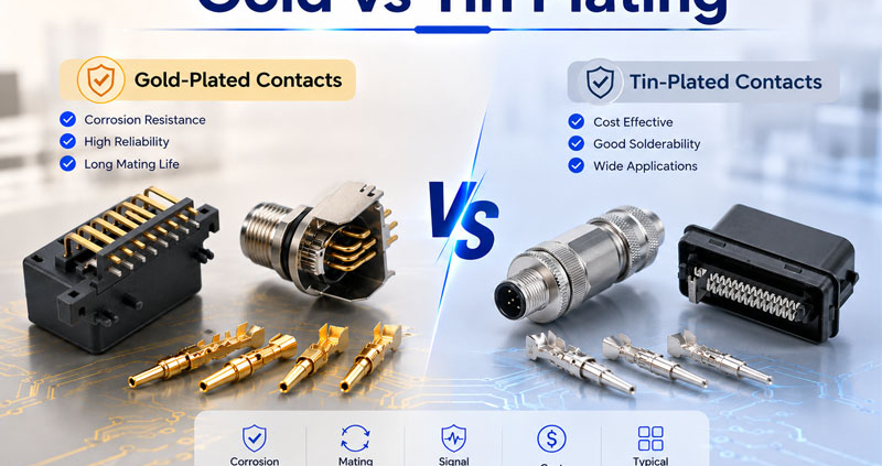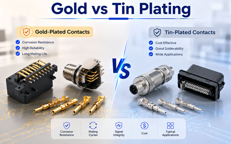
Gold vs Tin Plating Connector Comparison

The performance of an electrical connector depends on more than its housing, locking mechanism, or IP rating. One of the most important—but often overlooked—factors is contact plating.

Gold and tin are the two most common plating materials used in electrical connectors. While both provide reliable electrical connections, they are designed for different operating conditions and performance priorities.

Selecting the wrong plating can lead to increased contact resistance, fretting corrosion, intermittent signals, or reduced service life.

This article explains how engineers can choose between gold-plated and tin-plated connectors based on current requirements, mating frequency, and operating environment.

Gold vs Tin Plating Connector Comparison


Why Connector Plating Matters

Connector contacts are repeatedly exposed to mechanical wear, electrical current, vibration, humidity, and temperature changes.

The plating material directly affects:

  • Contact resistance
  • Signal integrity
  • Corrosion resistance
  • Wear resistance
  • Mating cycle life
  • Long-term reliability

Even when two connectors have identical mechanical designs, different contact plating can significantly influence their performance over time.


Gold-Plated Connectors

Gold is widely used in high-performance connectors because it offers excellent conductivity and exceptional resistance to oxidation.

Advantages

  • Extremely low contact resistance
  • Excellent signal integrity
  • Superior corrosion resistance
  • Outstanding wear resistance
  • Stable performance in humid environments
  • Suitable for high mating cycles

Typical applications include:

  • Medical equipment
  • Robotics
  • Industrial Ethernet
  • Aerospace systems
  • Precision test equipment
  • High-speed communication

Gold plating is especially recommended where reliable low-current signal transmission is critical.


Tin-Plated Connectors

Tin plating is one of the most common and cost-effective contact finishes.

Advantages

  • Lower manufacturing cost
  • Good conductivity
  • Suitable for higher current applications
  • Easy solderability
  • Widely used in industrial equipment

Typical applications include:

  • Power distribution
  • Automotive wiring
  • Industrial machinery
  • Control cabinets
  • General electrical equipment

Tin plating performs well in applications with relatively low mating frequency and stable operating conditions.


Current Carrying Capability

Many engineers assume gold-plated contacts always carry more current.

In reality, current capacity is determined primarily by contact design, contact area, conductor size, and temperature rise—not by the plating material alone.

However, plating still influences long-term electrical stability.

Gold plating maintains consistently low contact resistance over time, while tin plating may gradually increase resistance if oxidation develops under certain environmental conditions.


Mating Cycles: Where Gold Has a Clear Advantage

Repeated insertion and removal gradually wear the contact surface.

Gold-plated contacts generally provide:

  • Lower insertion wear
  • Stable contact resistance
  • Reduced fretting corrosion
  • Longer service life

Applications requiring thousands of mating cycles—such as medical devices, testing equipment, and modular automation systems—typically benefit from gold-plated contacts.

Tin-plated connectors are often more suitable for applications where connectors remain mated for extended periods with infrequent maintenance.


Environmental Considerations

Operating conditions have a major influence on plating selection.

Gold-Plated Contacts

Recommended for:

  • High humidity
  • Corrosive environments
  • Outdoor electronics
  • Industrial automation
  • High-speed data transmission

Tin-Plated Contacts

Recommended for:

  • Indoor electrical equipment
  • Dry industrial environments
  • Power connections
  • Cost-sensitive applications

Engineers should evaluate not only today’s operating conditions but also long-term environmental exposure.


Cost vs Lifecycle Value

Tin plating generally offers lower initial cost.

Gold plating typically requires higher manufacturing investment due to the precious metal content.

However, total ownership cost should also include:

  • Maintenance frequency
  • Downtime risk
  • Contact replacement
  • Equipment reliability
  • Product lifecycle

For mission-critical equipment, the higher initial cost of gold plating is often offset by improved long-term reliability.


Choosing the Right Contact Finish

Selection FactorGold PlatingTin Plating
Contact ResistanceExcellentGood
Corrosion ResistanceExcellentModerate
Mating CyclesExcellentModerate
Low-Current SignalsExcellentGood
High-Speed DataExcellentGood
Power ApplicationsGoodExcellent
CostHigherLower
Long-Term ReliabilityExcellentGood

Rather than asking which plating is better, engineers should determine which finish best matches the electrical, mechanical, and environmental requirements of the application.


How FPIC Supports High-Reliability Connector Solutions

FPIC manufactures circular connectors, push-pull self-locking connectors, waterproof connectors, and customized cable assemblies with both gold-plated and tin-plated contact options.

Our engineering team helps customers select the appropriate contact finish based on current rating, mating frequency, environmental conditions, and application requirements. Whether for industrial automation, robotics, medical equipment, or outdoor systems, FPIC delivers connector solutions designed for long-term reliability and consistent electrical performance.


Final Thoughts

Gold and tin plating each offer distinct advantages.

Gold-plated connectors excel in high-reliability, high-cycle, and signal-sensitive applications, while tin-plated connectors provide a cost-effective solution for many power and general industrial applications.

The right choice depends not only on electrical specifications but also on mating frequency, environmental conditions, maintenance strategy, and expected service life.

Selecting the correct contact finish helps maximize connector reliability and reduce long-term operating costs.


FAQ

Is gold plating always better than tin plating?

Not necessarily. Gold plating offers better corrosion resistance and mating durability, while tin plating is often a cost-effective choice for power applications with low mating frequency.

Does gold plating increase current capacity?

Current capacity mainly depends on contact design and conductor size. Gold plating primarily improves contact stability and corrosion resistance rather than significantly increasing current carrying capability.

Which plating is better for repeated mating?

Gold plating is generally preferred for applications requiring frequent connection and disconnection because it provides better wear resistance and more stable contact performance.

Are tin-plated connectors suitable for industrial automation?

Yes. Tin-plated connectors are widely used in industrial power distribution and general machinery where operating conditions are stable and connectors are not frequently mated.

How should engineers choose connector plating?

Selection should be based on electrical performance, current requirements, mating cycles, environmental exposure, maintenance frequency, and overall lifecycle cost.


Looking for the Right Connector Contact Finish?

FPIC provides circular connectors, push-pull self-locking connectors, waterproof connectors, and custom cable assemblies with both gold-plated and tin-plated contact options. Our engineering team can help you choose the most suitable contact finish for your application, balancing electrical performance, durability, environmental protection, and cost.

Contact FPIC today to discuss your connector application.


Resources

  1. IEC 60512 – Connectors for Electronic Equipment – Tests and Measurements
    https://webstore.iec.ch/
    Defines standardized test methods for connector contacts, including contact resistance, durability, and mechanical performance.
  2. IEC 61076 – Connectors for Electrical and Electronic Equipment
    https://webstore.iec.ch/
    Provides international standards for circular and industrial connector design, performance, and contact systems.
  3. TE Connectivity – Understanding Connector Contact Plating
    https://www.te.com/
    Technical guidance on gold and tin plating, wear mechanisms, contact resistance, and application selection.
  4. Harwin – Connector Contact Plating Explained
    https://www.harwin.com/
    Explains how different plating materials influence connector reliability, mating life, and corrosion resistance.
  5. Samtec – Contact Plating in High-Reliability Connectors
    https://www.samtec.com/
    Provides engineering resources on plating thickness, contact durability, and signal integrity for high-performance connector systems.
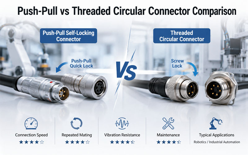
Push-Pull vs Threaded Circular Connectors Comparison

Circular connectors are widely used in industrial automation, robotics, medical devices, test equipment, and communication systems because they provide reliable electrical connections in demanding environments.

Two of the most common locking mechanisms are push-pull and threaded connectors. Both offer excellent electrical performance, but they are designed for different operating priorities.

When connectors are frequently connected and disconnected during equipment maintenance, tool changes, or production testing, the locking mechanism becomes just as important as the electrical specifications.

This article compares push-pull and threaded circular connectors from the perspective of repeated mating performance, helping engineers choose the right solution for long-term reliability.

Push-Pull vs Threaded Circular Connectors Comparison


Understanding the Two Locking Mechanisms

Although both connector types perform the same basic function, their locking principles are very different.

Push-Pull Connectors

Push-pull connectors automatically lock when inserted and can be released with a simple pull on the outer sleeve.

Key characteristics include:

  • One-handed operation
  • Automatic self-locking
  • Fast connection and disconnection
  • Compact structure
  • Reduced installation time

They are commonly used in:

  • Collaborative robots
  • Medical devices
  • Test equipment
  • Portable instruments
  • High-end industrial automation

Threaded Circular Connectors

Threaded connectors use screw threads to mechanically secure the connection.

Key characteristics include:

  • High locking force
  • Excellent vibration resistance
  • Reliable mechanical stability
  • Proven industrial performance

Typical applications include:

  • Servo motors
  • Machine tools
  • Heavy industrial equipment
  • Outdoor automation
  • Mobile machinery

Repeated Mating Performance

Repeated insertion and extraction gradually wear connector contacts and locking mechanisms.

For applications requiring frequent maintenance or module replacement, engineers should consider:

  • Mating cycle life
  • Ease of operation
  • Contact stability
  • Mechanical wear

Push-pull connectors are generally designed for rapid, repeatable operation with minimal handling effort.

Threaded connectors remain highly durable but require additional time to tighten and loosen during each connection cycle.


Maintenance Efficiency

Maintenance time directly affects production uptime.

Push-Pull Advantages

Because no threading is required, push-pull connectors allow technicians to:

  • Connect faster
  • Disconnect quickly
  • Operate with one hand
  • Reduce maintenance time
  • Lower the risk of improper tightening

These advantages are especially valuable in automated production lines where minimizing downtime is critical.


Threaded Connector Considerations

Threaded connectors require several turns to fully engage or disengage.

While this provides excellent mechanical security, it can increase maintenance time in applications with frequent connector changes.


Vibration Resistance

Industrial environments often expose connectors to continuous vibration and mechanical shock.

Threaded connectors have long been recognized for their strong vibration resistance due to their secure mechanical engagement.

Modern push-pull connectors, however, incorporate advanced self-locking mechanisms that provide reliable resistance to accidental disconnection while enabling much faster operation.

The choice depends on both the vibration level and maintenance frequency of the application.


Ergonomics and Operator Experience

Connector usability becomes increasingly important when operators repeatedly perform connection tasks.

Push-pull connectors offer several ergonomic benefits:

  • Reduced hand fatigue
  • Faster operation
  • Intuitive locking
  • Consistent mating force

Threaded connectors may require additional torque, particularly when connectors are installed in confined spaces.


Durability and Mating Cycles

Both connector types can achieve long service lives when properly designed.

Typical performance factors include:

  • Contact material
  • Gold plating thickness
  • Spring design
  • Housing material
  • Manufacturing precision

High-quality push-pull connectors are commonly designed for 5,000 or more mating cycles, making them well suited for applications involving frequent reconnection.

Threaded connectors also provide excellent durability, particularly in installations where connectors remain mated for extended periods.


How FPIC Supports High-Reliability Connector Solutions

FPIC develops push-pull self-locking connectors, circular connectors, and customized connector solutions for robotics, medical equipment, industrial automation, and testing systems.

Our push-pull connector series combines fast mating, secure locking, high-quality gold-plated contacts, and long mating life to help customers improve maintenance efficiency without compromising reliability. Backed by more than 23 years of manufacturing experience, FPIC supports projects from prototype development through high-volume production.


Final Thoughts

Push-pull and threaded circular connectors both provide reliable electrical connections, but they excel in different environments.

For applications involving frequent mating cycles, rapid maintenance, and operator convenience, push-pull connectors often deliver significant productivity advantages.

For heavy-duty environments where maximum mechanical retention is the priority, threaded connectors remain an excellent choice.

Understanding the operating environment, maintenance requirements, and expected mating frequency is the key to selecting the most suitable connector.


FAQ

Are push-pull connectors suitable for industrial automation?

Yes. Modern push-pull connectors are widely used in industrial automation, robotics, and medical equipment because they combine secure locking with fast connection and disconnection.

Which connector type is better for repeated mating?

Push-pull connectors are generally better suited for applications requiring frequent connection cycles because they reduce operating time and simplify maintenance.

Are threaded connectors more resistant to vibration?

Threaded connectors typically provide excellent vibration resistance through their mechanical screw-locking design, making them ideal for heavy industrial applications.

How many mating cycles can a push-pull connector withstand?

High-quality push-pull connectors are commonly designed for 5,000 or more mating cycles, depending on the connector series and operating conditions.

How should engineers choose between push-pull and threaded connectors?

The decision should be based on maintenance frequency, vibration level, available installation space, required mating speed, and overall application requirements.


Looking for High-Performance Push-Pull and Circular Connectors?

Whether your application requires rapid repeated mating or maximum mechanical retention, FPIC provides high-quality push-pull self-locking connectors and circular connectors engineered for robotics, industrial automation, medical equipment, and precision instrumentation. Our engineering team can help you select the right connector solution to improve reliability, simplify maintenance, and support long-term performance.

Contact FPIC today to discuss your connector application.


Resources

  1. IEC 61076 – Connectors for Electrical and Electronic Equipment
    https://webstore.iec.ch/
    Provides international standards covering the design, performance, and testing of circular and industrial connectors.
  2. IEC 60512 – Connectors for Electronic Equipment – Tests and Measurements
    https://webstore.iec.ch/
    Specifies standardized mechanical, electrical, and environmental test methods, including connector durability and mating cycle evaluations.
  3. LEMO – Push-Pull Connector Technology
    https://www.lemo.com/
    Introduces the principles, advantages, and applications of push-pull self-latching connector systems.
  4. ODU – Circular Connector Solutions
    https://www.odu-connectors.com/
    Provides technical resources on high-cycle mating connectors for medical, industrial, and testing applications.
  5. TE Connectivity – Circular Industrial Connectors
    https://www.te.com/
    Offers guidance on connector selection, durability, vibration resistance, and industrial interconnect solutions.
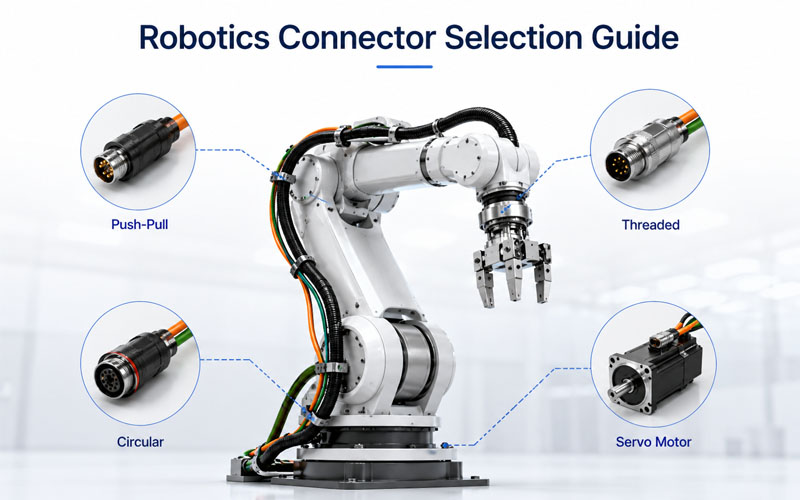
Robotics Connector Selection Guide

Industrial robots operate in demanding environments where connectors are exposed to constant motion, vibration, electromagnetic interference (EMI), and frequent maintenance. While much attention is often given to servo motors and robot controllers, connector selection is equally important for ensuring reliable power delivery and stable signal transmission.

A poorly selected connector can loosen under vibration, introduce communication errors, restrict cable movement, or shorten cable life. Choosing the right connector requires more than matching the voltage and current ratings—it involves evaluating the complete operating environment.

This article explains the key considerations when selecting connectors for robotic systems, focusing on locking mechanisms, EMC shielding, cable exit orientation, and long-term durability.

Robotics Connector Selection Guide


Why Connector Selection Matters in Robotics

Unlike stationary industrial equipment, robotic systems perform continuous multi-axis movements that repeatedly bend, twist, and accelerate cables.

Connectors must therefore withstand:

  • Continuous vibration
  • Frequent movement
  • Mechanical shock
  • Electromagnetic interference
  • Repeated mating cycles
  • Limited installation space

Connector reliability directly influences machine uptime and maintenance costs.


Choosing the Right Locking Mechanism

One of the most critical connector features is the locking system.

A connector that loosens during robot operation can interrupt power or communication, causing unexpected machine stops.

Common locking mechanisms include:

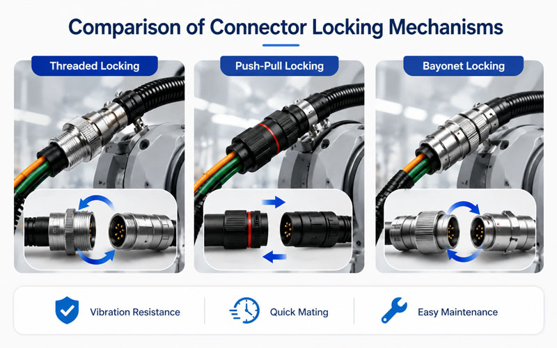
Threaded Locking

Advantages:

  • Excellent vibration resistance
  • High mechanical strength
  • Suitable for industrial automation

Applications:

  • Servo motors
  • Industrial robots
  • Machine tools

Push-Pull Locking

Advantages:

  • Quick connection and disconnection
  • Secure automatic locking
  • Compact design
  • Fast maintenance

Applications:

  • Collaborative robots (Cobots)
  • Medical robots
  • Inspection equipment
  • Automated production lines

Bayonet Locking

Advantages:

  • Fast quarter-turn locking
  • Good vibration performance
  • Reliable positioning

Applications:

  • Mobile robots
  • Outdoor equipment
  • Industrial machinery

Selecting the locking method should balance installation efficiency with vibration resistance.

Comparison of Connector Locking Mechanisms


Why Shielding Is Essential

Modern robots contain numerous high-speed electrical devices, including:

  • Servo drives
  • Frequency converters
  • Industrial Ethernet
  • Encoders
  • Vision systems

These devices generate electromagnetic interference that may affect communication signals.

Shielded connectors help:

  • Reduce EMI
  • Improve signal integrity
  • Lower communication errors
  • Support high-speed data transmission

Proper shield continuity between cable and connector is essential for achieving effective EMC performance.


Selecting the Best Cable Exit Direction

Cable exit orientation is often overlooked during connector selection.

However, it directly affects cable stress and available installation space.

Typical exit options include:

Straight Exit

Best for:

  • Open installation space
  • Linear cable routing
  • Easy assembly

Right-Angle Exit

Best for:

  • Compact robot joints
  • Tight cabinet layouts
  • Reduced bending stress
  • Improved cable management

Proper cable exit selection helps extend cable flex life and minimizes mechanical strain near the connector.


Environmental Protection Requirements

Robots frequently operate in challenging environments.

Connector selection should consider:

  • Dust
  • Water spray
  • Oil
  • Coolant
  • Metal particles
  • Cleaning chemicals

Depending on the application, connectors may require:

  • IP67 protection
  • IP68 protection
  • IP69K protection

Environmental sealing improves long-term reliability and reduces maintenance frequency.


Connector Durability and Mating Cycles

Industrial robots often require periodic replacement of end effectors or tooling.

Frequent connection and disconnection demand connectors with long mating life.

Typical industrial requirements include:

  • More than 500 insertion cycles
  • 2,000–5,000 cycles for automation equipment
  • Higher durability for collaborative robots and testing equipment

Gold-plated contacts further improve contact stability and corrosion resistance.


Size and Weight Considerations

As robots become smaller and faster, connector size becomes increasingly important.

Compact connectors provide:

  • Lower moving mass
  • Improved joint flexibility
  • Easier cable routing
  • Better space utilization

Miniaturization is especially important in collaborative robots and precision automation equipment.


Validation Before Deployment

Connectors should be validated under realistic operating conditions.

Recommended tests include:

  • Vibration testing
  • Mechanical shock testing
  • Cable flex testing
  • Salt spray testing
  • Contact resistance measurement
  • Insertion and extraction force testing
  • EMC verification
  • Environmental sealing tests

System-level validation provides the highest confidence in connector performance.


How FPIC Supports Robotics Connector Solutions

FPIC develops high-performance connector solutions for industrial automation, robotics, and intelligent manufacturing.

Our product portfolio includes push-pull self-locking connectors, circular connectors, waterproof connectors, and customized connector assemblies designed for demanding robotic applications. With over 23 years of manufacturing experience, FPIC supports customers from rapid prototyping through mass production, providing reliable connectivity solutions that improve equipment uptime and long-term performance.


Final Thoughts

Selecting the right connector for robotic applications involves much more than matching electrical specifications.

Locking mechanisms, shielding performance, cable exit orientation, environmental protection, and durability all influence system reliability.

As robotic systems continue to become faster, smarter, and more compact, connector design plays an increasingly important role in maintaining stable operation and reducing maintenance costs.


FAQ

Why are locking connectors important in robotics?

Locking mechanisms prevent accidental disconnection caused by vibration, motion, or mechanical shock, improving system reliability.

When should shielded connectors be used?

Shielded connectors are recommended whenever high-speed communication or servo systems operate in environments with significant electromagnetic interference.

Which cable exit is better, straight or right-angle?

It depends on available space and cable routing. Right-angle exits are often preferred in compact robot joints to reduce bending stress.

What IP rating is recommended for industrial robots?

Many industrial robots require IP67 protection, while washdown or outdoor applications may require IP68 or IP69K connectors.

How are robotics connectors validated?

Typical validation includes vibration, cable flex, EMC, sealing, mating cycle, and contact resistance testing.


Looking for Reliable Connectors for Robotics and Industrial Automation?

FPIC provides high-performance connector solutions for industrial robots, collaborative robots, servo systems, and automated equipment. From push-pull self-locking connectors to waterproof circular connectors, our engineering team helps customers select the right connectivity solution for demanding motion applications.

Contact FPIC today to discuss your robotics connector requirements.


Resources

  1. IEC 60529 – Degrees of Protection Provided by Enclosures (IP Code)
    https://webstore.iec.ch/
    Defines IP ratings such as IP67, IP68, and IP69K for connector protection against dust and water ingress.
  2. IEC 61076 – Connectors for Electrical and Electronic Equipment
    https://webstore.iec.ch/
    International standards covering the design, performance, and testing of industrial connectors.
  3. ODVA – EtherNet/IP Physical Layer and Industrial Connectivity
    https://www.odva.org/
    Provides technical guidance on industrial Ethernet connectivity and connector performance in automation systems.
  4. TE Connectivity – Industrial Robotics Connectivity Solutions
    https://www.te.com/
    Explains connector technologies, shielding solutions, and rugged interconnect systems for robotics and automation.
  5. Phoenix Contact – Connectors for Industrial Automation
    https://www.phoenixcontact.com/
    Offers technical resources on circular connectors, EMC protection, and reliable industrial connectivity.
Select High-Voltage Connectors for BESS Cabinets

BESS cabinets are getting more powerful, more compact, and more demanding. That is changing the way engineers and sourcing teams evaluate high-voltage connectors. What used to be treated as a simple power connection is now part of a broader discussion about safety, thermal stability, installation efficiency, and long-term operating risk.

If you are selecting connectors for a battery energy storage cabinet, the right question is no longer just “What voltage and current do I need?” A better question is “Which connector platform helps the cabinet operate more safely, integrate more cleanly, and remain easier to build and maintain over time?”

Why Connector Selection in BESS Cabinets Is Becoming More Strategic

A BESS cabinet is not just a box full of batteries. It is a system-level power architecture that must manage electrical load, temperature, mechanical layout, installation logic, maintenance access, and compliance expectations at the same time.

Inside that architecture, the connector sits in a critical position. It can link battery modules, racks, busbars, cabinet-level power paths, and distribution interfaces. That means connector selection affects much more than the simple ability to pass current.

A poorly chosen connector can create avoidable problems such as:

  • excess temperature rise at the interface
  • difficult routing in compact cabinet layouts
  • inconsistent installation on the production floor
  • polarity or mating mistakes during assembly or service
  • poor maintenance access during replacement
  • lower long-term reliability under real operating conditions

By contrast, a well-selected high-voltage connector helps make the cabinet safer, cleaner to integrate, and easier to manage over the full system lifecycle.

Start with the Real Application, Not Just the Catalog Spec

One of the most common mistakes in connector selection is to begin and end with rated voltage and rated current. Those values matter, but they do not tell the full story.

In BESS cabinet design, you should first define the real application environment:

1. Where is the connector used in the system?

A connector used for a battery rack interface does not always face the same requirements as one used for an internal cabinet power path or a service interface.

2. What load conditions will it actually see?

A catalog rating may look sufficient, but the real question is whether the connector can support the required current with stable contact behavior and acceptable temperature rise in the actual cabinet environment.

3. How will the connector be installed and serviced?

If the design requires fast, repeatable installation or easier field replacement, connector structure becomes just as important as electrical performance.

Selection becomes much easier when you treat the connector as a system interface rather than a standalone part.

Safety Should Be the First Screening Standard

In a high-voltage BESS cabinet, safety is not a secondary attribute. It is a first-level filter.

When reviewing connector options, teams should evaluate whether the design supports safer installation and operation in real conditions.

1. Touch-Proof Structure

Touch-proof design helps reduce the risk of accidental contact with energized conductive points. This is especially valuable during cabinet assembly, maintenance, and replacement operations.

2. Polarity Clarity and Anti-Misplug Design

In modular energy storage systems, polarity mistakes create unnecessary risk. Mechanical keying, coding, and clear positive/negative differentiation can help reduce installation errors.

3. Secure Mating Logic

A connector should provide stable electrical and mechanical engagement. Secure mating improves confidence during assembly and helps maintain contact stability during operation.

4. Application-Appropriate Compliance Direction

Many customers now consider compliance readiness earlier in the design cycle. Even when the final certification belongs to the complete system, connector selection still affects the path toward safer and more credible product integration.

Current Rating Must Be Evaluated Together with Thermal Performance

Current rating is still a basic selection parameter, but in BESS cabinets it should always be considered together with thermal performance.

Why? Because a connector that carries current on paper can still become a weak point in the cabinet if contact resistance is unstable or if heat builds up in a tight installation space.

That is why engineers should evaluate:

  • rated current
  • conductor compatibility
  • contact resistance stability
  • termination method
  • expected temperature rise
  • real cabinet airflow and space constraints

This is where high-current connector design becomes more than a numbers exercise. It becomes a thermal and reliability decision.

Installation Efficiency Matters More Than Many Teams Expect

In large-scale BESS deployment, installation speed and consistency matter. Connector design directly affects both.

A connector that supports a cleaner mating process, better cable routing, and clearer installation logic can help reduce:

  • assembly time
  • operator error
  • rework risk
  • field service time later

This is why the market is paying more attention to connector systems that improve installation, not only electrical transfer.

For BESS cabinet builders, connection efficiency can influence both production cost and long-term service experience.

Do Not Ignore Serviceability and Maintenance Access

BESS systems are long-life assets. That means maintainability should be part of connector selection from the beginning.

A connector that is difficult to reach, hard to disconnect, or easy to reconnect incorrectly may create future service cost even if it performs acceptably on day one.

Good high-voltage connector selection should therefore consider:

  • access during inspection
  • clarity during remating
  • replacement convenience
  • compatibility with modular cabinet design

In practice, the best connector is often the one that supports both stable operation and more predictable service work.

What to Look for in a High-Voltage Connector for BESS Cabinets

A practical selection checklist usually includes the following questions:

  • 1. Is the voltage platform aligned with the target system?

The connector should fit the actual platform requirement, whether the project is centered on 1000V, 1500V, or higher-voltage development.

  •  2. Is the current rating suitable for real cabinet conditions?

Do not treat rated current as an isolated number. Confirm the connector matches the true load path and thermal expectations.

  • 3. Does the structure support safer use?

Look for features such as touch-proof protection, mechanical keying, polarity control, and stable locking.

  • 4. Does it integrate well into the cabinet design?

Panel mounting logic, cable routing, space efficiency, and mating orientation all affect integration quality.

  • 5. Will the connector support installation and maintenance efficiency?

Selection should support not only the first assembly, but also future service and replacement.

Where FPIC’s 2000V 450A Energy Storage Connector Fits

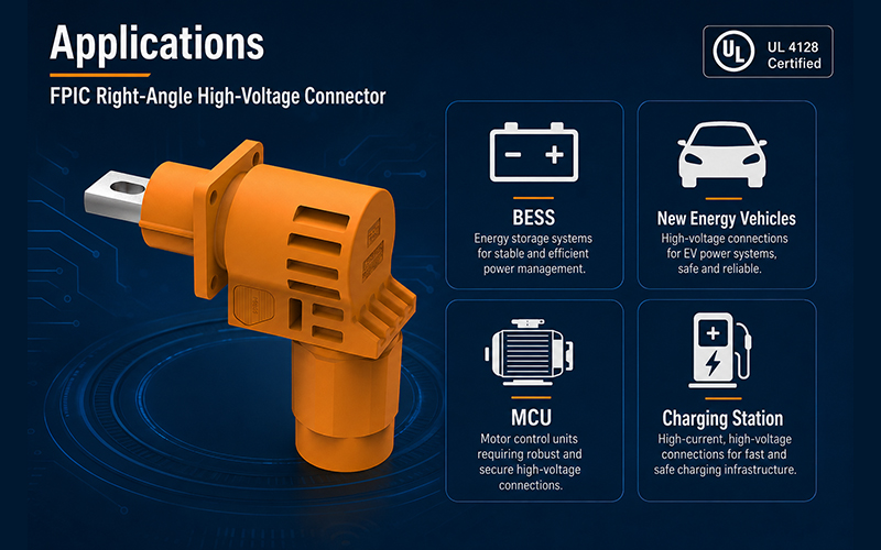
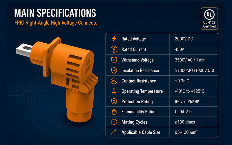
For customers developing higher-voltage and higher-current BESS cabinet systems, FPIC’s 2000V 450A energy storage connector offers a strong option for projects that need more than a basic power interface.

This connector direction is relevant when the application requires:

  • higher-voltage connector capability
  • stronger high-current support
  • cabinet-level safety-oriented connection design
  • structured installation logic
  • improved routing flexibility
  • support for more advanced battery-system integration

FPIC’s energy storage connector development already includes features such as touch-proof design, 360° rotating plug structure, different installation keying options, and multiple connection methods, which are directly relevant to the practical needs of BESS cabinet integration.

That makes the product easier to position not just as a connector, but as part of a safer and more serviceable cabinet interconnection solution.

How FPIC Supports Broader Energy Storage Connector Needs

FPIC’s energy storage connector portfolio is not limited to one flagship product. Internal product materials already cover multiple platform levels, including 1000V and 1500V ES series configurations, with different current ranges and structural options for energy storage applications.

This broader platform logic matters because BESS customers do not all need the same interface level. Some projects focus on mainstream 1500V cabinet architectures. Others increasingly move toward higher-voltage, higher-current platforms where the 2000V 450A direction becomes more attractive.

That gives FPIC a stronger story in content marketing and customer communication:

  • 1000V and 1500V platforms support broader application coverage
  • 2000V 450A supports higher-power differentiation
  • safety-oriented structure supports BESS cabinet messaging
  • UL-related product positioning supports stronger credibility in global discussions

Select High-Voltage Connectors for BESS Cabinets

Final Recommendation

If you are selecting a high-voltage connector for a BESS cabinet, do not reduce the decision to voltage and current alone.

Instead, evaluate the connector from five angles:

  • safety
  • current and thermal stability
  • installation efficiency
  • cabinet integration fit
  • maintenance practicality

That approach leads to better system decisions and reduces the risk of solving one problem while creating another.

As the BESS market keeps moving toward safer, more integrated, and more serviceable systems, high-voltage connector selection will continue to play a larger role in overall cabinet design quality.

Contact FPIC

Looking for a high-voltage connector solution for BESS cabinets, battery racks, or high-current storage systems?

FPIC can support connector communication and product matching for energy storage applications, including higher-power projects that require stronger safety and integration logic.

Email: info@fpiconn.com
Website: fpiconn.com

Resources

  • Reuters. Lithium producers bet on battery storage as demand shifts beyond EVs. June 24, 2026.
  • Molex. Designing Battery Energy Storage Systems (BESS).
  • Phoenix Contact. Connectors for Energy Storage Systems.
  • Connector Supplier. Battery Connectors: The Unsung Heroes of BESS Applications.
2000V 450A BESS Connectors

Selecting a 2000V 450A energy storage connector for BESS cabinets requires more than checking current and voltage ratings. Engineers should verify UL certification, temperature rise performance, creepage and clearance design, IP protection, touch-proof safety, locking reliability, anti-misplug structure, and cable assembly compatibility before platform design is finalized.

To select a 2000V 450A BESS connector, focus on seven factors: certified safety, stable temperature rise, high-voltage insulation, IP protection, secure locking, anti-misplug design, and reliable cable assembly support. These requirements should be confirmed early because connector platforms are usually locked during cabinet design.

Why 2000V 450A BESS Connectors Matter

Battery energy storage systems are moving toward higher voltage, higher current, and more standardized cabinet architecture. As system integrators pursue higher energy density and faster installation, the connector is no longer a simple accessory. It becomes a safety-critical and maintenance-critical interface inside the BESS cabinet.

A 2000V 450A energy storage connector must support stable high-current transmission while helping reduce installation risk, service complexity, and long-term field failure. For this reason, connector selection should happen early in the cabinet design stage, not after the power architecture is already fixed.

For BESS cabinet designers, the right connector can help improve:

  • High-voltage safety
  • Installation efficiency
  • Maintenance convenience
  • System reliability
  • Cabinet standardization
  • Cable assembly consistency
  • Long-term platform scalability

This is why UL certification, temperature rise, sealing, locking, and cable integration should be treated as core selection criteria.

1. Start with UL Certification and Safety Compliance

For high-voltage BESS applications, certification is one of the first items customers should verify. A connector used in a 2000V 450A system must not only carry current; it must prove that its insulation, materials, structure, and safety design can support demanding electrical conditions.

UL certification gives customers stronger confidence during project evaluation, especially when the connector will be used in energy storage cabinets, battery racks, power distribution modules, or system-level platforms that require safety documentation.

When reviewing a connector, ask these questions:

  • Is the connector UL certified?
  • Is the certification aligned with the intended voltage and current platform?
  • Are materials suitable for high-voltage energy storage systems?
  • Does the supplier provide documentation for project review?
  • Can the connector be introduced into customer platforms early?

FPIC’s 2000V 450A UL energy storage connector is designed for high-voltage BESS cabinet applications where safety, compliance, and long-term reliability are essential.

2000V 450A BESS Connectors

2. Check Temperature Rise Under High Current

Temperature rise is one of the most important performance indicators for high-current connectors. At 450A, even small contact resistance can create heat. If heat is not controlled, the system may face higher power loss, material aging, or reliability risk.

When choosing a 2000V 450A BESS connector, engineers should not only ask for the rated current. They should also review the connector’s temperature rise performance under realistic working conditions.

Important factors include:

  • Contact resistance
  • Terminal structure
  • Contact material
  • Plating quality
  • Cable size
  • Crimping or termination quality
  • Ambient temperature
  • Cabinet ventilation conditions

A good high-current connector should maintain stable electrical performance and avoid localized overheating. For BESS cabinets, this is especially important because connectors often operate inside enclosed or semi-enclosed power systems.

FPIC supports connector and cable assembly integration, helping customers match the connector with suitable cable specifications and assembly methods to improve current-carrying stability.

3. Verify High-Voltage Insulation, Creepage, and Clearance

In a 2000V energy storage system, insulation design is critical. The connector must maintain enough electrical separation between conductive parts to reduce the risk of arcing, breakdown, or short circuit.

Three terms are especially important:

Creepage distance
The shortest path along the insulating surface between conductive parts.

Clearance distance
The shortest air distance between conductive parts.

Insulation resistance
The ability of insulating materials to prevent unwanted current leakage.

For high-voltage BESS cabinets, these parameters are often considered early in platform design. Once the cabinet layout, busbar direction, cable routing, and connector interface are fixed, changing the connector later can be costly.

That is why connector selection should be part of the system architecture review, not only a purchasing decision.

4. Choose IP Protection for Real Cabinet Conditions

BESS cabinets may operate in indoor, outdoor, or semi-outdoor environments. Even when the cabinet itself has protection, connectors may still face dust, humidity, condensation, vibration, or maintenance exposure.

A suitable energy storage connector should offer strong environmental protection. IP-rated sealing helps protect the connection area from water and dust ingress, supporting more stable long-term operation.

When evaluating IP protection, consider:

  • Cabinet installation environment
  • Indoor or outdoor exposure
  • Humidity and condensation risk
  • Maintenance frequency
  • Cable outlet direction
  • Sealing structure after assembly

For energy storage connectors, IP protection is not only about passing a test. It is about maintaining stable performance throughout installation, operation, inspection, and maintenance.

FPIC’s energy storage connector solutions are designed with environmental protection in mind, including sealing structures suitable for demanding power storage applications.

5. Pay Attention to Locking and Serviceability

High-current connectors used in BESS cabinets must remain secure during operation. Vibration, cable tension, installation stress, and maintenance handling can all affect connection stability.

A reliable locking design helps prevent accidental loosening and supports safer field operation.

For BESS cabinet applications, a good locking design should provide:

  • Secure mating
  • Clear locking feedback
  • Convenient unlocking during maintenance
  • Stable connection under cable stress
  • Reduced risk of improper operation

Serviceability is becoming increasingly important in energy storage systems. Traditional bolted connections and busbar systems may require more assembly time and tool access. In many modern BESS platforms, maintainable connector solutions can help improve installation and maintenance efficiency.

FPIC energy storage connectors are designed to support practical cabinet installation and field maintenance requirements, helping customers improve system operation convenience.

6. Use Anti-Misplug Design to Reduce Installation Risk

In high-voltage BESS cabinets, incorrect mating can create serious safety risks. Anti-misplug design helps prevent wrong polarity connection, incorrect position matching, or mismatched connector pairing.

Key anti-misplug features may include:

  • Different keying positions
  • Color identification
  • Positive and negative polarity distinction
  • Mechanical coding
  • Dedicated plug and receptacle matching

For cabinet standardization, this becomes especially valuable. When multiple connectors are installed in similar cabinet positions, clear anti-misplug design helps reduce assembly errors and maintenance mistakes.

FPIC energy storage connector solutions can support different keying and identification designs to help customers improve installation safety and platform consistency.

7. Evaluate Cable Assembly Capability

A high-voltage connector is only as reliable as its cable assembly. For a 2000V 450A connector, cable selection, stripping, crimping, sealing, strain relief, and final testing all affect long-term performance.

Customers should evaluate whether the supplier can provide complete connector and cable assembly support, not just separate components.

Important cable assembly factors include:

  • Cable size compatibility
  • Crimping process control
  • Contact resistance control
  • Pull force performance
  • Sealing after assembly
  • Polarity and labeling
  • 100% electrical testing
  • Packaging and installation protection

This is where FPIC can provide stronger project value. With connector manufacturing and cable assembly capability, FPIC can support customers from connector selection to finished cable assembly delivery, helping reduce supplier coordination and improve project consistency.

Selection Checklist for 2000V 450A BESS Connectors

Before confirming a connector platform, review this checklist:

Selection FactorWhat to Check
Voltage RatingSuitable for 2000V system design
Current RatingStable 450A current-carrying performance
CertificationUL certification and project documentation
Temperature RiseControlled heating under high current
Creepage & ClearanceSafe high-voltage insulation design
IP ProtectionProtection against dust and moisture
Locking DesignSecure mating and safe maintenance
Anti-Misplug DesignKeying, color, and polarity protection
Cable AssemblyCable size, crimping, sealing, and testing
Supplier SupportEngineering review and mass production capability

This checklist helps engineering and sourcing teams evaluate energy storage connectors more systematically.

Where FPIC Adds Value

FPIC’s 2000V 450A UL energy storage connector is developed for BESS cabinet applications where high-voltage safety, current stability, and serviceability matter.

FPIC supports customers with:

  • 2000V 450A UL energy storage connector solutions
  • High-current connector design support
  • IP protection and sealing design
  • Secure locking and anti-misplug structures
  • Cable assembly and harness integration
  • Customization for cabinet and platform requirements
  • Engineering support from sample development to mass production

With 23 years of connector and cable assembly manufacturing experience, FPIC understands that BESS projects require more than a connector part number. Customers need a stable platform, certified product support, and a supplier capable of practical engineering cooperation.

Conclusion

Selecting a 2000V 450A energy storage connector for BESS cabinets requires a full system view. Voltage and current ratings are only the starting point. UL certification, temperature rise, insulation design, IP protection, locking, anti-misplug structure, and cable assembly capability all influence long-term safety and reliability.

If you are developing BESS cabinets, battery racks, or high-voltage energy storage platforms, FPIC can support your connector selection, customization, and cable assembly requirements.

Contact FPIC to discuss your 2000V 450A energy storage connector project.

Resources / References

  1. Future Market Insights – Energy Storage High Voltage Connector Market, 2026–2036 forecast.
  2. Connector Supplier – High-current connector specification trends for industrial equipment.
  3. FPIC internal and product information – energy storage connector features, safety design, IP protection, and cable assembly capability.

References / Notes

This article is originally written for FPIC based on energy storage connector market trends, FPIC’s product development direction, and general engineering selection principles for high-voltage BESS cabinet connectors. External market information is referenced and should be cited when published.

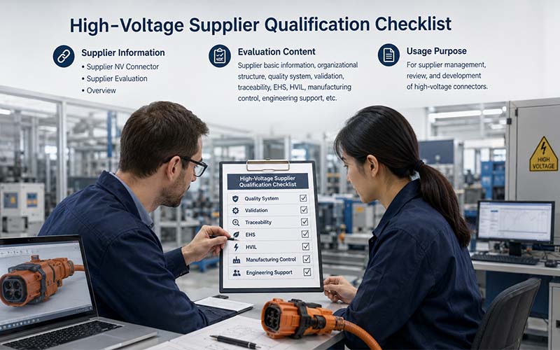
High-Voltage Connector Supplier Qualification Checklist

In EV, energy storage, and industrial electrification projects, high-voltage connector are safety-critical components.

A connector failure can lead to:

  • vehicle shutdown
  • thermal damage
  • EMC issues
  • field recalls
  • safety risks
  • costly warranty claims

For OEM buyers, supplier selection is therefore not only a purchasing decision—it is a long-term quality and risk management decision.

Yet many sourcing evaluations still focus too heavily on price and catalog specifications.

This article explains the key technical, manufacturing, and quality factors OEM buyers should review before approving a high-voltage connector supplier.

High-Voltage Connector Supplier Qualification Checklist


Why Supplier Evaluation Matters

A high-voltage connector supplier becomes part of the OEM’s safety chain.

The supplier’s capabilities directly affect:

  • electrical reliability
  • production consistency
  • validation performance
  • traceability
  • launch timing
  • long-term field reliability

Even well-designed connectors can fail if manufacturing processes are unstable.


1.Review High-Voltage Application Experience

Not all connector manufacturers have genuine high-voltage expertise.

OEM buyers should confirm experience in:

  • EV battery systems
  • onboard chargers
  • inverters
  • ESS battery systems
  • industrial power electronics

High-voltage applications require different design and validation approaches compared with low-voltage connectors.


2.Verify Compliance with Automotive Quality Systems

A qualified supplier should operate under robust quality management systems such as:

  • IATF 16949
  • ISO 9001
  • ISO 14001

OEMs should verify:

  • certification status
  • audit performance
  • process discipline
  • corrective action systems

3.Evaluate Validation Capability

Suppliers should demonstrate the ability to perform or support:

  • temperature rise testing
  • contact resistance testing
  • vibration testing
  • thermal cycling
  • salt spray
  • sealing validation
  • HiPot testing
  • insulation resistance testing
  • HVIL functional validation
  • EMC-related validation

Validation capability is especially important for custom connector programs.


4.Assess Engineering Support

Strong engineering support often determines project success.

OEM buyers should evaluate whether the supplier can assist with:

  • connector selection
  • creepage and clearance review
  • shielding strategy
  • HVIL integration
  • cable routing
  • DFM (Design for Manufacturability)
  • tolerance analysis

Engineering responsiveness during development is critical.


5.Review Manufacturing Process Control

Manufacturing consistency is essential for high-voltage reliability.

Key areas to review include:

  • crimp process control
  • automated inspection
  • pull force testing
  • torque verification
  • traceability systems
  • SPC implementation
  • preventive maintenance

Process discipline often matters more than equipment appearance.


6.Inspect Traceability Systems

OEMs increasingly require full traceability.

Suppliers should be able to track:

  • raw materials
  • terminals
  • housings
  • plating lots
  • production dates
  • operators
  • inspection records

Fast containment capability reduces recall risk.


7.Check Shielding and EMC Expertise

Modern EV systems require strong EMC performance.

Suppliers should understand:

  • 360° shield termination
  • transfer impedance
  • grounding strategy
  • shielding continuity
  • EMC validation requirements

This is particularly important for OBC and inverter applications.


8.Evaluate Tooling and Prototype Capability

A capable supplier should support:

  • rapid prototypes
  • low-volume pilot builds
  • validation samples
  • production tooling development
  • PPAP support

Prototype responsiveness often impacts vehicle launch schedules.


9.Review Supply Chain Stability

OEM buyers should assess:

  • material sourcing strategy
  • dual-source capability
  • inventory management
  • logistics reliability
  • capacity planning

Connector shortages can stop entire production lines.


10.Confirm Customization Capability

Many EV projects require customized solutions such as:

  • integrated HVIL
  • custom keying
  • special shielding
  • unique cable exits
  • compact packaging

Suppliers should demonstrate flexibility without compromising quality control.


11.Audit Failure Analysis Capability

When failures occur, suppliers should provide:

  • root cause analysis
  • microsection capability
  • contact resistance analysis
  • cross-functional corrective actions
  • 8D reporting

Problem-solving capability is a major supplier qualification factor.


12.Evaluate Long-Term Partnership Potential

The best suppliers act as engineering partners rather than transactional vendors.

OEM buyers should consider:

  • communication efficiency
  • technical transparency
  • responsiveness
  • launch support
  • continuous improvement culture

Long-term cooperation often reduces total project risk.


Common Supplier Approval Mistakes

Selecting Only on Unit Price

Low initial pricing may create larger long-term quality costs.

Ignoring Validation Capability

Insufficient testing support delays development.

Overlooking Traceability

Weak traceability increases recall exposure.

Underestimating EMC Expertise

Shielding problems are difficult to correct late in development.

Approving Suppliers Without Process Audits

Factory discipline matters more than presentations.


Questions OEM Buyers Should Ask

Before approval, OEM buyers should ask:

  • What high-voltage projects have you supported?
  • What validation tests can you perform internally?
  • How do you control crimp quality?
  • What traceability systems are in place?
  • How is EMC performance verified?
  • Can you support PPAP requirements?
  • What is your corrective action process?

The answers often reveal the supplier’s real maturity level.


How FPIC Supports OEM Programs

FPIC provides high-voltage connectors and cable assemblies for EV, ESS, and industrial applications.

Our support includes:

  • application engineering
  • custom connector development
  • HVIL integration
  • EMC and shielding support
  • validation testing
  • PPAP documentation
  • traceability systems

We work closely with OEMs and Tier suppliers from prototype through mass production.


Final Thoughts

Approving a high-voltage connector supplier requires more than reviewing technical specifications.

OEM buyers should evaluate:

  • engineering capability
  • manufacturing discipline
  • validation expertise
  • traceability
  • EMC understanding
  • long-term support capability

A reliable supplier helps reduce technical risk, launch delays, and field failures across the product lifecycle.


FAQ

Why is supplier evaluation critical for HV connectors?

Because connector failures can directly affect safety and vehicle reliability.

Should OEMs audit connector factories?

Yes. Process control and traceability should be verified onsite whenever possible.

Why is EMC expertise important?

Poor shielding design can cause communication and system stability problems.

Is prototype capability important?

Yes. Fast prototype support accelerates development and validation.

What certifications should suppliers have?

IATF 16949 and ISO 9001 are commonly expected in automotive programs.


Looking for a Reliable High-Voltage Connector Partner?

FPIC supports OEM and Tier projects with custom high-voltage connector and cable assembly solutions backed by engineering support, validation capability, and controlled manufacturing.

Contact us to discuss your EV or ESS connector program requirements.


Resources

  1. IATF 16949 Automotive Quality Management Standard
    Global automotive quality management requirements.
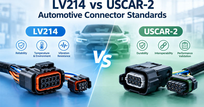
  2. USCAR-2 Automotive Connector Performance Specification
    Environmental and electrical validation requirements.
  3. LV214 Automotive Connector Validation Standard
    Connector qualification requirements used by major OEMs.
  4. ISO 6469 – EV Safety Requirements
    Safety specifications for electrically propelled vehicles.
  5. TE Connectivity – High Voltage Connectivity Solutions
    Engineering guidance for EV high-voltage interconnect systems.
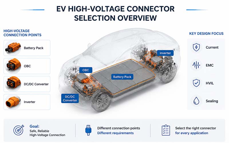
EV High-Voltage Connector Selection Overview

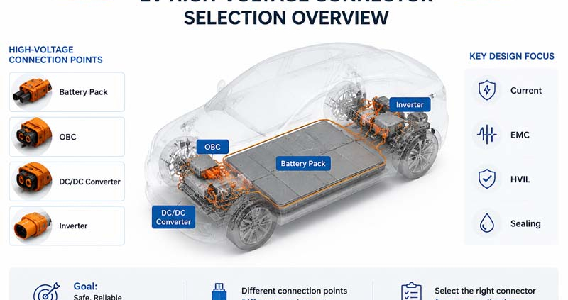
High-voltage connectors are critical interfaces in electric vehicles (EVs), battery energy storage systems (ESS), and industrial electrification platforms.

They connect major subsystems such as:

  • battery packs
  • onboard chargers (OBC)
  • DC/DC converters
  • inverters
  • power distribution units (PDU)

Although these connectors may appear similar, each application has distinct electrical, mechanical, thermal, and EMC requirements.

This article explains how engineers can select the right high-voltage connector for battery pack, OBC, and DC/DC interfaces.

EV High-Voltage Connector Selection Overview


Step 1: Define Electrical Requirements

The first step is to establish the electrical operating conditions.

Key parameters include:

  • nominal and maximum voltage
  • continuous current
  • peak current
  • allowable temperature rise
  • insulation resistance requirements
  • dielectric withstand requirements

For example:

  • Battery pack connectors may carry several hundred amps.
  • OBC connectors typically carry lower current but may require excellent shielding.
  • DC/DC connectors often combine high current and compact packaging.

Step 2: Evaluate Safety Requirements

High-voltage connectors must meet electrical safety expectations such as:

  • creepage and clearance distances
  • touch-safe design
  • HVIL integration
  • CPA locking features
  • ingress protection

Safety requirements depend on standards, OEM specifications, and application risk assessments.


Step 3: Consider Mechanical Packaging

Packaging constraints strongly influence connector selection.

Important factors include:

  • available installation space
  • cable bend radius
  • mating access
  • keying and polarization
  • mounting method

Compact designs often require trade-offs between size and performance.


Step 4: Assess Environmental Conditions

Connectors must survive the real operating environment.

Consider:

  • temperature range
  • vibration
  • humidity
  • salt exposure
  • dust and water ingress
  • chemical exposure

Battery pack connectors usually require high sealing performance.


Step 5: Review EMC and Shielding Needs

Applications near switching power electronics may require:

  • shielded cable interfaces
  • 360° shield termination
  • conductive backshells
  • low-impedance grounding

OBC and DC/DC interfaces are especially sensitive to EMC requirements.


Step 6: Confirm Current Carrying Capability

Current rating should be validated using:

  • conductor size
  • terminal design
  • contact resistance
  • thermal rise testing
  • cooling conditions

Do not rely solely on catalog current ratings.


Step 7: Evaluate Contact Technology

Important considerations include:

  • contact material
  • plating system
  • contact normal force
  • resistance stability

Reliable low-resistance performance is essential for high-current applications.


Step 8: Determine HVIL Requirements

Many EV systems require integrated HVIL circuits.

HVIL is commonly used in:

  • battery pack connectors
  • service disconnects
  • OBC interfaces

Verify interlock sequencing and connector compatibility.


Step 9: Consider Serviceability

Field maintenance may require:

  • easy disconnect
  • visual mating confirmation
  • ergonomic locking mechanisms
  • replacement without removing adjacent components

Serviceability is particularly important for battery packs.


Step 10: Validate Supplier Capability

Evaluate whether the supplier can provide:

  • application engineering support
  • prototype samples
  • custom cable assemblies
  • validation reports
  • PPAP documentation
  • production traceability

Supplier capability is as important as connector specifications.


Typical Priorities by Application

Battery Pack Connectors

Primary concerns:

  • high current capacity
  • HVIL
  • sealing
  • vibration resistance
  • serviceability

OBC Connectors

Primary concerns:

  • EMC shielding
  • compact size
  • thermal performance

DC/DC Connectors

Primary concerns:

  • current density
  • packaging
  • shielding
  • temperature performance

Common Selection Mistakes

Choosing Based Only on Current Rating

Thermal and environmental performance must also be verified.

Ignoring Shield Termination

Can create EMC problems.

Overlooking Service Access

May complicate maintenance.

Underestimating Packaging Constraints

Can lead to late redesign.

Not Defining Validation Requirements Early

Delays supplier qualification.


Validation Tests to Request

Typical validation activities include:

  • temperature rise
  • contact resistance
  • vibration
  • thermal cycling
  • sealing tests
  • HiPot and insulation resistance
  • HVIL functional testing
  • EMC testing

How FPIC Supports High-Voltage Connector Selection

FPIC provides custom high-voltage connectors and cable assemblies for EV, ESS, and industrial systems.

Our engineering support includes:

  • application analysis
  • connector selection
  • HVIL integration
  • shielding design
  • prototype development
  • validation testing

We help customers balance safety, EMC performance, packaging, and cost.


Final Thoughts

Selecting the right high-voltage connector requires a system-level view.

Engineers should consider:

  • electrical requirements
  • insulation design
  • shielding
  • environmental exposure
  • serviceability
  • supplier capability

A well-chosen connector improves reliability, safety, and manufacturability across the entire product lifecycle.


FAQ

What is the most important factor when selecting a high-voltage connector?

There is no single factor. Voltage, current, safety, environment, and packaging must all be considered.

Do all EV high-voltage connectors require HVIL?

Not all, but HVIL is widely used for safety-critical interfaces.

Why is shielding important for OBC connectors?

OBC systems generate switching noise that can affect EMC performance.

Can catalog current ratings be used directly?

They should be verified under actual operating conditions.

What validation tests are typically required?

Temperature rise, vibration, sealing, HiPot, and HVIL functional testing.


Selecting High-Voltage Connectors for Your EV or ESS Project?

FPIC provides engineering support and custom high-voltage connector and cable assembly solutions for battery packs, OBCs, and DC/DC converters.

Contact us to discuss your application requirements.


Resources

  1. ISO 6469 – Safety Specifications for Electrically Propelled Vehicles
    Core safety requirements for EV high-voltage systems.
  2. LV215 / LV214 Automotive High-Voltage Connector Standards
    Requirements for high-voltage connectors and cable assemblies.
  3. USCAR-2 – Automotive Connector Performance Specification
    Environmental and electrical validation methods.
  4. TE Connectivity – EV High Voltage Connector Selection Guide
    Practical guidance for subsystem connector selection.
  5. Molex – EV Power Connectivity Solutions
    Connector technologies for battery and power electronics.
terminals

Electrical terminals play a critical role in every interconnect system. Whether used in automotive electronics, industrial equipment, new energy systems, or consumer devices, the quality of a terminal directly affects conductivity, mechanical stability, and long-term reliability.

With 23 years of precision manufacturing experience, FPIC provides a full range of customized terminals, including press-fit terminals, composite terminals, crimp terminals, and special terminals designed for complex applications. Our comprehensive R&D and automated production capabilities allow us to support both rapid prototyping and high-volume mass production for global customers.


Why Terminals Matter in Modern Electronics

As devices become more compact and performance-driven, terminals must deliver:

  • Stable electrical conductivity

  • Mechanical strength under vibration

  • Heat resistance and corrosion resistance

  • Precise tolerances for automated assembly

  • Long-term durability over thousands of cycles

High-quality terminals ensure secure connections and reduce failure rates in demanding environments such as automotive, industrial automation, robotics, and energy storage systems.

FPIC’s terminal solutions are engineered to meet these requirements under strict automotive-grade standards.

terminals


1. Press-Fit Terminals

Press-fit terminals are designed for solderless PCB insertion, providing secure mechanical retention and excellent conductivity. They allow for:

  • Heat-free PCB assembly

  • Reduced production defects

  • Strong insertion force retention

  • High current-carrying capability

FPIC offers fully customized geometries, plating options, and materials. Our terminals comply with automotive cleanliness and dimensional requirements suitable for high-reliability applications such as car electronics, control units, and power modules.


2. Composite Terminals

Composite terminals integrate multiple metal structures into a single component—ideal for customers requiring complex performance characteristics.

Advantages include:

  • Engineered multi-layer designs

  • Improved structural strength

  • Optimized current paths

  • High precision for automated assembly

FPIC utilizes advanced stamping, welding, and component integration processes to deliver composite terminals tailored to unique product requirements.


3. Crimp Terminals

Crimp terminals remain one of the most widely used terminal types, providing secure wire-to-terminal contact through controlled deformation.

FPIC’s crimp terminals offer:

  • Reliable pull-out force

  • Consistent crimp height tolerances

  • Compatibility with automatic crimping equipment

  • High-speed mass production

These terminals are ideal for wire harnesses, automotive connectors, industrial control systems, and many other wiring applications.


4. Customized Terminal Solutions

FPIC specializes in developing fully customized terminals based on customer drawings, electrical requirements, and end-use applications.

Customization includes:

  • Unique shapes and locking structures

  • Plating materials and thickness (e.g., gold, tin, silver)

  • High-temperature and high-voltage performance

  • Multi-step forming and progressive stamping

  • Surface treatments and secondary machining

All terminal projects follow a zero-risk development process, covering simulation, prototyping, validation, and mass-production readiness.


FPIC’s Manufacturing Strengths

Automated Production

Our stamping and terminal assembly lines are fully automated, ensuring:

  • High precision forming

  • Consistent quality

  • Lower defect rates

  • High throughput capacity

Automotive-Grade Quality

FPIC meets global standards, ensuring long-term reliability:

  • IATF 16949 certified

  • VDA 19.1 / ISO 16232 cleanliness compliant

  • Terminal plating reliability tested for corrosion, wear, and conductivity

Trusted by Global Brands

FPIC is a Tier-2 supplier to major automotive manufacturers such as:
BMW, VW, Porsche, Renault, Ford, and many others.

This reflects our ability to deliver stable quality, fast response, and scalable production capacity.


Applications of FPIC Terminals

Our terminals are used across:

  • Automotive control modules

  • Energy storage systems

  • Industrial machinery

  • Robotics & automation

  • Communication devices

  • Consumer electronics

  • Medical equipment

Every terminal is engineered to provide stable performance even in harsh or high-demand environments.


Conclusion

Terminals may be small components, but they are essential for the reliability of any electrical system. With advanced engineering, automated production, and strict quality controls, FPIC delivers terminal solutions that meet the evolving needs of global industries.

Whether you need press-fit, composite, crimp, or fully customized terminals, FPIC provides end-to-end support from concept to mass production.

📩 Contact FPIC: info@fpiconn.com
🔗 https://fpiconn.com

Copper Busbar Supplier

Copper busbars are essential components in a variety of industries, including automotive, energy, industrial equipment, and telecommunications. Their reliability, conductivity, and durability make them critical for power distribution and electrical systems. However, finding the right supplier for copper busbars can be challenging. At Shenzhen Forman Precision Industry Co., Ltd, we understand the importance of selecting the perfect supplier to meet your needs. Here are 10 key considerations to guide you through the decision-making process:

Copper Busbar Supplier


1. Material Quality

The quality of copper used in busbars directly impacts their electrical conductivity and performance. Ensure that the supplier provides high-purity copper (e.g., 99.9% pure) to guarantee minimal energy loss and optimal efficiency. Shenzhen Forman Precision Industry Co., Ltd uses only premium materials to ensure long-lasting, high-performance copper busbars.


2. Customization Capabilities

Every project has unique requirements. A reliable supplier should offer customization options for dimensions, shapes, coatings, and other specifications. At Shenzhen Forman, we specialize in designing and manufacturing custom copper busbars tailored to your exact needs, ensuring seamless integration into your applications.


3. Advanced Manufacturing Techniques

Modern manufacturing processes like CNC machining, stamping, and automated bending ensure precise and consistent production. Suppliers who invest in advanced equipment and technology can deliver high-quality products at competitive costs. Our state-of-the-art facilities at Shenzhen Forman enable us to provide precision manufacturing for even the most complex busbar designs.


4. Compliance with Industry Standards

Ensure that the supplier adheres to global industry standards, such as ISO, RoHS, and UL certifications. This guarantees product reliability, safety, and environmental compliance. Shenzhen Forman Precision Industry Co., Ltd operates under strict quality control systems and complies with major certifications to meet global market demands.


5. Thermal and Electrical Performance

Copper busbars must maintain excellent conductivity and thermal management under various conditions. Evaluate the supplier’s ability to design busbars that can handle specific voltage, current, and heat requirements without compromising performance.


6. Surface Treatment Options

Surface treatments such as tin plating, nickel plating, or powder coating protect busbars from corrosion and enhance durability. Make sure your supplier offers multiple finishing options to suit different environments. Shenzhen Forman provides a wide range of coating solutions, ensuring your busbars meet both aesthetic and functional requirements.


7. Delivery Time and Scalability

A reliable supplier should meet deadlines and scale production to accommodate your growing needs. Shenzhen Forman offers flexible manufacturing capacities and efficient delivery systems, ensuring your projects stay on schedule.


8. Cost-Effectiveness

While quality is paramount, affordability is also a critical factor. Look for suppliers offering competitive pricing without compromising on performance. With Shenzhen Forman’s streamlined manufacturing processes and bulk production capabilities, we provide cost-effective solutions that don’t sacrifice quality.


9. Expertise in Diverse Applications

Choose a supplier with experience across various industries, such as automotive, renewable energy, and industrial automation. Shenzhen Forman Precision Industry Co., Ltd has decades of experience serving diverse markets, making us a trusted partner for your copper busbar needs.


10. After-Sales Support

Strong after-sales service ensures you get the technical support and guidance you need for installation, troubleshooting, and maintenance. Shenzhen Forman prioritizes customer satisfaction with comprehensive after-sales support and a dedicated team of experts.


Why Choose Shenzhen Forman Precision Industry Co., Ltd?

At Shenzhen Forman Precision Industry Co., Ltd, we combine decades of industry expertise with cutting-edge manufacturing capabilities to deliver copper busbars that exceed expectations. From raw material selection to design, development, and delivery, we are committed to providing high-quality, reliable, and cost-effective solutions for our global customers.


Conclusion
Choosing the right copper busbar supplier is critical to ensuring the efficiency and durability of your electrical systems. By considering factors like material quality, customization, compliance, and support, you can make an informed decision. Trust Shenzhen Forman Precision Industry Co., Ltd to be your partner in success, delivering world-class copper busbars and comprehensive services to power your projects.

For inquiries and custom solutions, contact us today at info@fpiconn.com.

Heat Sink Supplier

Introduction:

Choosing the right heat sink supplier is crucial for ensuring optimal thermal management and performance in your electronic devices. With numerous suppliers offering a variety of heatsink solutions, selecting the best partner for your specific requirements can be challenging. In this article, we’ll discuss key factors to consider when choosing a heat sink supplier to meet your needs effectively.

stamping fin heat sink

A001-0001-C0B2

Aluminum Cooler

A001-0002-C0B2

Expertise and Experience:

Look for a heat sink supplier with extensive expertise and experience in thermal management solutions. A supplier with a proven track record of delivering high-quality heatsinks across diverse industries is more likely to understand your unique requirements and provide tailored solutions.


Customization Capabilities:

Evaluate the supplier’s customization capabilities to ensure they can meet your specific design and performance specifications. A reputable supplier should offer flexible customization options, including customized fin profiles, materials, and surface treatments, to address your unique thermal management challenges.


Quality and Reliability:

Quality and reliability are paramount when selecting a heat sink supplier. Choose a supplier that adheres to stringent quality control standards and employs rigorous testing procedures to ensure the durability, performance, and consistency of their heatsinks. Look for certifications such as ISO 9001 and ISO 14001 to verify the supplier’s commitment to quality.


Technical Support:

Consider the level of technical support and expertise offered by the supplier. A reliable supplier should provide comprehensive technical assistance, including thermal analysis, design optimization, and engineering support, to help you select the most suitable heatsink solution for your application.


Production Capacity and Lead Times:

Assess the supplier’s production capacity and lead times to ensure they can meet your project timelines and volume requirements. Choose a supplier with sufficient manufacturing capabilities and a responsive supply chain to deliver heatsinks promptly and efficiently, minimizing downtime and delays.


Cost-effectiveness:

While cost is an important consideration, prioritize value over price when selecting a heat sink supplier. Evaluate the overall cost-effectiveness of the heatsink solutions, taking into account factors such as performance, reliability, customization options, and long-term support services, to ensure maximum return on investment.


Conclusion:

Selecting the right heat sink supplier is crucial for achieving optimal thermal management and performance in your electronic devices. By considering factors such as expertise, customization capabilities, quality, technical support, production capacity, and cost-effectiveness, you can choose a reliable partner that meets your specific needs and delivers high-quality heatsink solutions tailored to your requirements.