supplier evaluation

We are thrilled to share that FPIC has received an outstanding supplier evaluation from one of our esteemed German automotive customers for the year 2023. This evaluation reflects our unwavering commitment to quality, reliability, and exceptional service.

Supplier Evaluation Highlights

  • Quality Reliability: 100%
  • Quantity Reliability: 100%
  • Delivery Date Reliability: 95%
  • Delivery Obligation: 98%
  • Certification: 100%

With an overall score of 99%, FPIC has been classified as an A-level supplier, underscoring our excellence in providing top-tier automotive connectors. This recognition is a testament to the hard work and dedication of our team in maintaining the highest standards in the industry.

automotive electronics connector application diagram

What This Means for Our Customers

Unmatched Quality: Our connectors meet the highest quality standards, ensuring reliable performance and longevity in automotive applications.

Consistent Supply: We pride ourselves on our ability to deliver the exact quantities needed, without compromising on quality or timeliness.

Timely Deliveries: With a 95% delivery date reliability, we ensure that our products reach you when you need them, minimizing any potential disruptions to your production schedules.

Adherence to Commitments: Our 98% delivery obligation score highlights our dedication to fulfilling our commitments and providing consistent, dependable service.

Certified Excellence: Achieving 100% in certification reflects our compliance with all necessary industry standards, giving you confidence in the safety and reliability of our products.

supplier evaluation

Customer Confidence

At FPIC, we understand that our customers rely on us for products that meet stringent automotive standards. This top-tier evaluation from a respected German automotive customer reinforces our position as a trusted supplier in the global market.

We invite you to experience the same level of quality and reliability that earned us this A-level classification. Whether you are looking for automotive connectors or other precision components, FPIC is committed to delivering excellence in every product we supply.

Get in Touch

If you have any questions or would like to learn more about our products and services, please contact us at info@fpiconn.com. Our team is ready to assist you and ensure your satisfaction with our offerings.

Thank you for your continued trust and support. We look forward to serving you with the best in class connectors and components.

By choosing FPIC, you are partnering with a company that is dedicated to quality, reliability, and superior customer service. Let us help you achieve success in your automotive projects with our top-rated connectors.

Connector Failure Analysis in Vehicles

Automotive connectors are designed to operate reliably for more than a decade under demanding conditions. However, many field failures are not caused by design flaws alone, but by a combination of environmental stress, installation conditions, and long-term degradation mechanisms.

Understanding how and why connectors fail is critical for improving system reliability, reducing warranty costs, and optimizing design decisions early in development.

Among the most common and impactful failure mechanisms in vehicles are fretting corrosion, water ingress, and thermal stress. These factors often act together, accelerating degradation beyond what isolated testing may predict.


Why Connector Failure Analysis Matters

Connector failures rarely occur as sudden events. Most are the result of gradual degradation processes that evolve over time.

Without proper failure analysis:

  • root causes may be misidentified
  • corrective actions may be ineffective
  • the same issues may repeat across projects

A structured failure analysis approach helps engineers link symptoms to underlying mechanisms and implement targeted improvements.

Connector Failure Analysis in Vehicles


Fretting Corrosion: The Hidden Failure Mechanism

Fretting corrosion is one of the most common causes of intermittent electrical failure in automotive connectors.

How It Happens

  • vibration causes micro-motion between contact surfaces
  • protective plating wears away
  • oxide debris forms at the interface
  • electrical resistance increases

This process is often invisible from the outside, making it difficult to detect during inspection.


Typical Symptoms

  • intermittent signal loss
  • unstable electrical performance
  • increased contact resistance
  • no visible mechanical damage

Where It Occurs

  • engine bay connectors
  • chassis-mounted harnesses
  • high-vibration zones

Water Ingress: The Silent Reliability Killer

Water ingress occurs when moisture penetrates the connector interface or wiring system.

Causes

  • insufficient sealing design
  • damaged or misassembled seals
  • improper connector orientation
  • aging of sealing materials

Effects

  • corrosion of terminals
  • increased contact resistance
  • short circuits or leakage paths
  • long-term degradation of insulation

High-Risk Scenarios

  • underbody applications
  • areas exposed to road spray or pressure washing
  • connectors with compromised sealing integrity

Even connectors with high IP ratings can fail if sealing is not maintained during assembly or service.


Thermal Stress: Long-Term Degradation Driver

Thermal stress results from repeated temperature changes and heat generation during operation.

Sources

  • ambient temperature variation
  • heat from nearby components
  • current-induced heating (I²R losses)

Effects on Connectors

  • material expansion and contraction
  • loss of contact force
  • seal degradation
  • accelerated aging of materials

Combined Effects

Thermal stress often amplifies other failure mechanisms:

  • increased temperature accelerates corrosion
  • material softening reduces mechanical stability
  • cycling creates micro-movements that lead to fretting

Why Failures Are Often Multi-Factor

In real automotive environments, failures are rarely caused by a single factor.

For example:

  • vibration → fretting corrosion
  • moisture → oxidation
  • temperature → material degradation

These factors interact, creating compounded effects that are more severe than individual stresses.

This is why connectors that pass standard tests may still fail in field conditions.


Failure Analysis Methods

A systematic approach to connector failure analysis typically includes:

Visual Inspection

  • check for corrosion, discoloration, or damage

Electrical Testing

  • measure contact resistance
  • check continuity and insulation

Microscopic Analysis

  • identify fretting wear or oxide layers

Environmental Testing

  • reproduce failure under controlled stress conditions

Prevention Strategies

Design Level

  • select appropriate materials and plating
  • ensure sufficient contact force
  • design for sealing and environmental protection

System Level

  • optimize harness routing to reduce vibration
  • avoid water accumulation points
  • ensure proper connector orientation

Manufacturing and Assembly

  • ensure correct seal installation
  • maintain consistent crimp quality
  • control assembly processes

Validation

  • include combined stress testing
  • simulate real installation conditions
  • perform long-term aging tests

How FPIC Supports Failure Prevention

Preventing connector failure requires integration across design, manufacturing, and validation.

FPIC supports customers with:

  • connector and harness design optimization
  • sealing and routing strategy review
  • controlled assembly processes
  • validation aligned with real-world conditions

By addressing failure mechanisms early, long-term reliability can be significantly improved.


Final Thoughts

Connector failures in vehicles are rarely random. They are the result of predictable physical and environmental processes.

Fretting corrosion, water ingress, and thermal stress are among the most critical factors affecting long-term reliability—and they often work together.

Understanding these mechanisms allows engineers to move from reactive troubleshooting to proactive design improvement.


FAQ

What is the most common cause of connector failure in vehicles?

Fretting corrosion caused by vibration is one of the most common causes, especially in high-vibration environments.

Can sealed connectors prevent all water ingress issues?

No. Sealing effectiveness depends on design, assembly quality, and long-term material performance.

How does temperature affect connector reliability?

Thermal cycling can reduce contact force, degrade materials, and accelerate other failure mechanisms.

Why do connectors fail even after passing tests?

Because real-world conditions often involve combined stresses that are not fully replicated in standard testing.

How can connector failures be reduced?

Through proper design, material selection, assembly control, and realistic validation testing.


CTA

Reduce Connector Failure Risk in Your System

Understanding failure mechanisms is the first step toward building reliable systems.

FPIC provides connector and wire harness solutions designed for real-world conditions, helping reduce failure risk and improve long-term performance.

Contact us to discuss your application challenges.


Resources

  1. USCAR-2 – Automotive Connector Performance Specification: defines durability and environmental testing methods for connectors.
  2. TE Connectivity – Fretting Corrosion in Electrical Contacts: explains vibration-induced degradation mechanisms.
  3. Molex – Sealed Connector Design and Water Ingress: discusses sealing strategies and failure risks.
  4. Amphenol – Thermal Effects on Connector Systems: covers temperature-related reliability challenges.
  5. IEC 60512 – Connector Testing Standards: provides standard test methods for electrical connectors.
Automotive connectors installation zones and environmental exposure

In automotive electrical systems, connectors selection is not only about current rating or pin count. One of the most critical decisions is whether to use a sealed or unsealed connector.

This choice directly affects reliability, cost, assembly complexity, and long-term performance. Selecting the wrong type for a given installation zone can lead to corrosion, signal issues, or premature failure.

This article explains the differences between sealed and unsealed connectors, and how to select the right type based on real automotive installation environments.


What Are Sealed and Unsealed Connectors?

Sealed Connectors

Sealed connectors are designed to prevent the ingress of water, dust, and contaminants. They typically include:

  • wire seals (grommets)
  • interface seals (between connector halves)
  • housing features that maintain compression

They are commonly rated using IP (Ingress Protection) standards such as IP67 or IP69K.


Unsealed Connectors

Unsealed connectors do not include environmental sealing features. They are:

  • simpler in design
  • easier to assemble
  • more cost-effective

They rely on installation in protected environments where exposure to moisture or contaminants is minimal.

Automotive Installation Zones Diagram


Why Installation Zone Matters

The key factor in connector selection is not the connector itself—but where it is installed.

Automotive systems can be divided into several environmental zones, each with different risk levels.


Typical Automotive Installation Zones

Zone 1: Exterior / Underbody / Engine Bay

Examples:

  • engine compartment
  • underbody harnesses
  • wheel area sensors

Environmental Conditions:

  • water splash and immersion
  • mud, salt, and chemicals
  • high temperature variation
  • strong vibration

Recommendation:
Use sealed connectors with high IP ratings (IP67 or higher).

Failure to use sealing in this zone will almost certainly lead to corrosion and electrical failure.


Zone 2: Semi-Protected Areas

Examples:

  • trunk area
  • door interiors
  • near HVAC systems

Environmental Conditions:

  • occasional moisture
  • condensation
  • moderate temperature variation

Recommendation:
Use sealed connectors or partially sealed designs, depending on risk level.

Designers should consider worst-case conditions such as water ingress or condensation buildup.


Zone 3: Interior Cabin (Protected Zone)

Examples:

  • dashboard electronics
  • infotainment systems
  • interior wiring

Environmental Conditions:

  • stable temperature
  • minimal moisture
  • low contamination risk

Recommendation:
Use unsealed connectors for cost efficiency and ease of assembly.

Sealed connectors in this zone may increase cost without providing meaningful benefits.


Understanding IP Ratings

Sealed connectors are often classified using IP ratings.

For example:

  • IP67: protected against dust and temporary water immersion
  • IP68: protected against continuous immersion (depending on specification)
  • IP69K: resistant to high-pressure, high-temperature water spray

However, IP rating alone does not guarantee long-term reliability. It reflects test conditions, not full lifecycle performance.


Trade-Offs Between Sealed and Unsealed Connectors

Sealed Connectors

Advantages:

  • protection against water and contaminants
  • improved long-term reliability in harsh environments
  • reduced risk of corrosion

Challenges:

  • higher cost
  • more complex assembly
  • higher insertion force
  • more difficult serviceability

Unsealed Connectors

Advantages:

  • lower cost
  • easier assembly and maintenance
  • lower insertion force
  • simpler design

Challenges:

  • limited environmental protection
  • higher risk if used in incorrect location

Common Design Mistakes

Over-Specifying Sealing

Using sealed connectors in low-risk environments:

  • increases cost unnecessarily
  • complicates assembly
  • reduces efficiency

Under-Specifying Protection

Using unsealed connectors in harsh environments:

  • leads to corrosion and failure
  • causes intermittent electrical issues
  • increases warranty risk

Ignoring Real Installation Conditions

Design decisions based only on CAD layout rather than real-world exposure can lead to incorrect connector selection.


Beyond Sealing: System-Level Considerations

Connector reliability depends on more than sealing alone.

Other critical factors include:

  • harness routing (water accumulation risk)
  • drainage paths
  • connector orientation
  • strain relief and fixation
  • ventilation vs sealing balance

A sealed connector installed incorrectly can still fail.


How FPIC Supports Connector Selection

Selecting the right connector requires understanding both the product and the application environment.

FPIC supports customers with:

  • connector selection based on installation zones
  • custom wire harness integration
  • sealing and protection strategy review
  • design for manufacturability (DFM)
  • validation support under real conditions

By aligning connector design with real-world usage, reliability risks can be significantly reduced.


Final Thoughts

Choosing between sealed and unsealed connectors is a fundamental decision in automotive design.

The correct approach is not to always choose the most robust option—but to match the connector type to the installation environment.

A well-balanced design considers:

  • environmental exposure
  • cost efficiency
  • assembly complexity
  • long-term reliability

Understanding installation zones is the key to making the right decision.


FAQ

What is the main difference between sealed and unsealed connectors?

Sealed connectors include features that prevent water and dust ingress, while unsealed connectors do not.

Are sealed connectors always better?

No. They are necessary in harsh environments but may add unnecessary cost and complexity in protected areas.

What IP rating is typically required for automotive applications?

IP67 is common for exterior applications, while higher ratings like IP69K may be required for extreme conditions.

Can unsealed connectors be used in vehicles?

Yes, they are widely used in interior and protected zones.

What is the biggest risk in connector selection?

Using the wrong connector type for the installation environment.


Choose the Right Connector for Your Application

Selecting the correct connector type early in the design process can prevent costly failures and redesigns.

FPIC provides connector and wire harness solutions tailored to real automotive environments, balancing reliability, cost, and manufacturability.

Contact us to discuss your project requirements.


Resources

  1. IEC 60529 – IP Rating Standard: defines ingress protection levels for dust and water resistance.
  2. USCAR-2 – Automotive Connector Performance Specification: includes environmental and durability testing requirements.
  3. TE Connectivity – Sealed vs Unsealed Connector Design: explains design differences and application scenarios.
  4. Molex – Automotive Sealed Connector Systems: provides examples of sealed connector technologies and applications.
  5. Amphenol – Automotive Interconnect Solutions: covers connector design considerations for harsh environments.

In automotive electrical systems, Automotive connectors performance is often evaluated based on initial specifications—contact resistance, current capacity, and mechanical retention. However, long-term reliability is not determined at time zero. It is shaped by how these parameters evolve over time.

One of the most critical yet often underestimated factors is contact resistance drift.

Contact resistance drift refers to the gradual increase or fluctuation of resistance at the electrical interface between mating terminals. While the change may be small in absolute terms, its impact can be significant—especially in high-current, high-voltage, and signal-sensitive automotive systems.


Understanding Contact Resistance at the Interface Level

Electrical contacts are not perfectly smooth surfaces. Even highly polished terminals only touch at microscopic asperities.

This means:

  • the real contact area is much smaller than the apparent area
  • current flows through discrete micro-contact points
  • resistance is highly sensitive to surface condition and contact force

Any change in these micro-contact conditions—such as oxidation, wear, or reduced contact pressure—can increase resistance.

Over time, these small changes accumulate, resulting in measurable resistance drift.


Why Contact Resistance Drift Matters

Heat Generation and Thermal Runaway Risk

In power circuits, resistance increase leads directly to higher heat generation (I²R losses). This can create a feedback loop:

  • higher resistance → more heat
  • more heat → faster material degradation
  • degradation → further resistance increase

In severe cases, this can lead to localized overheating or even thermal runaway in high-power systems.

Contact Interface Microstructure


Voltage Drop and Efficiency Loss

In EV and power distribution systems, even a small resistance increase can result in:

  • measurable voltage drop
  • reduced energy efficiency
  • performance degradation in motors or inverters

As system voltages rise, maintaining stable connections becomes even more critical.


Signal Integrity Degradation

For low-current signal circuits, resistance drift affects:

  • signal amplitude
  • noise margin
  • communication stability

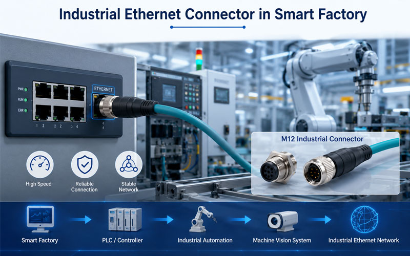
This is particularly important in CAN, LIN, and automotive Ethernet systems, where stable electrical characteristics are required for reliable data transmission.


Root Causes of Contact Resistance Drift

Contact resistance drift rarely has a single cause. It is typically the result of multiple interacting factors.

Fretting Corrosion

Micro-motion between contact surfaces caused by vibration leads to:

  • wear of protective plating
  • formation of oxide debris
  • increased contact resistance

This is one of the most common failure mechanisms in automotive connectors.


Oxidation and Environmental Exposure

Exposure to oxygen, humidity, and contaminants can form insulating layers on contact surfaces.

Key risk factors include:

  • unsealed connectors
  • harsh environmental conditions
  • long service life

Loss of Contact Force

Contact force is critical for maintaining a stable electrical interface. Over time, it can decrease due to:

  • material creep
  • thermal cycling
  • stress relaxation

Reduced force leads to smaller effective contact area and higher resistance.


Plating Degradation

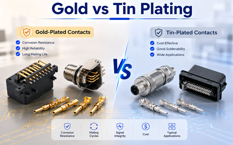
Surface plating (tin, silver, or gold) is designed to protect against corrosion and ensure conductivity. However:

  • repeated mating cycles can wear plating
  • vibration can accelerate degradation
  • base materials may oxidize once exposed
  • Contact Resistance Drift Process

Real-World Conditions Accelerate Drift

Laboratory testing often evaluates connectors under controlled conditions. However, real automotive environments introduce combined stresses:

  • continuous vibration from road conditions
  • wide temperature fluctuations
  • moisture, dust, and chemicals
  • harness movement and mechanical strain

These factors do not act independently—they interact and accelerate degradation mechanisms.

As a result, contact resistance drift in real applications is often faster and more complex than predicted by isolated testing.


High-Risk Automotive Applications

High-Current Systems

  • battery connections
  • inverter interfaces
  • power distribution units

These systems are sensitive to heat and efficiency loss.


High-Speed Data Systems

  • ADAS sensors
  • communication networks
  • control modules

These systems are sensitive to signal degradation.


Safety-Critical Systems

  • braking systems
  • airbag systems
  • vehicle control electronics

In these applications, even intermittent resistance variation can lead to unacceptable risk.


Strategies to Control Contact Resistance Drift

Optimize Contact Design

  • maintain stable contact force over time
  • design for vibration resistance
  • ensure sufficient contact area

Select Appropriate Materials and Plating

  • use corrosion-resistant materials
  • match plating type to application (tin vs gold)
  • consider mating cycle requirements

Improve Sealing and Environmental Protection

  • use sealed connectors in harsh environments
  • minimize exposure to moisture and contaminants

Control Harness Movement

  • reduce micro-motion through proper routing
  • add strain relief and fixation points
  • avoid unnecessary stress at connectors

Validate Under Realistic Conditions

Testing should include:

  • vibration + temperature combined testing
  • long-term aging simulation
  • real installation conditions

How FPIC Supports Stable Electrical Performance

Ensuring stable contact resistance requires coordination across connector design, cable assembly, and manufacturing processes.

FPIC supports customers with:

  • connector and cable integration design
  • controlled crimping and termination processes
  • application-based validation strategies
  • manufacturing consistency for long-term stability

By addressing both design and process variables, resistance drift can be effectively minimized.


Final Thoughts

Contact resistance drift is a slow but critical failure mechanism in automotive connectors. It does not cause immediate failure—but it gradually reduces system reliability until problems emerge.

As vehicles become more electrified and data-driven, the tolerance for electrical instability continues to decrease.

A robust connector design strategy must go beyond initial specifications and focus on long-term performance under real-world conditions.


FAQ

What is contact resistance drift?

It is the gradual increase or variation of resistance at an electrical contact interface over time.

Why is it important in automotive systems?

Because it affects heat generation, voltage stability, and signal integrity—critical factors in vehicle performance and safety.

What is the most common cause?

Fretting corrosion caused by vibration-induced micro-motion is one of the primary causes.

Can it be completely eliminated?

No, but it can be significantly reduced through design, material selection, and validation.

How is it tested?

Through contact resistance measurement under environmental stress conditions such as vibration and thermal cycling.


Improve Connector Reliability in Real Conditions

If your application involves high-current, high-voltage, or signal-critical systems, controlling contact resistance drift is essential.

FPIC provides custom connector and cable assembly solutions with a focus on long-term electrical stability and real-world reliability.

Contact us to discuss your project requirements.


Resources

  1. USCAR-2 – Performance Specification for Automotive Electrical Connector Systems: includes durability and contact resistance testing methods for automotive connectors.
  2. TE Connectivity – Contact Physics in Electrical Connectors: explains how micro-contact behavior influences resistance stability.
  3. Molex – Fretting Corrosion in Connector Systems: details the mechanisms behind resistance increase under vibration.
  4. Amphenol – Connector Design Fundamentals: covers materials, plating, and environmental considerations affecting electrical performance.
  5. IEC 60512 – Electrical Connector Testing: defines standardized methods for measuring contact resistance and durability.
Automotive connector

In automotive electrical systems, connector reliability is not only determined by material quality or contact design. Assembly accuracy plays an equally important role. Even a well-designed automotive connector can fail if it is not fully seated or if terminals are not properly locked in place.

To address these risks, modern automotive connectors often incorporate CPA (Connector Position Assurance) and TPA (Terminal Position Assurance) features. These mechanisms are designed to prevent assembly errors and ensure that connectors perform reliably under real-world conditions.

This article explains how CPA and TPA work, how they differ, and why they are essential for automotive connector reliability.

Automotive connector


Why Assembly Quality Matters in Connector Performance

Connector failures are often traced back to assembly-related issues rather than design flaws. Common problems include:

  • incomplete connector mating
  • terminal back-out during vibration
  • improper terminal insertion
  • insufficient locking force

These issues can lead to intermittent electrical contact, increased resistance, or complete system failure. In high-vibration automotive environments, even a small assembly defect can develop into a critical failure over time.

CPA and TPA mechanisms are specifically designed to reduce these risks.


What Is CPA (Connector Position Assurance)?

CPA is a secondary locking mechanism that ensures the connector is fully mated.

How CPA Works

The CPA device is typically a sliding or hinged component integrated into the connector housing. It can only be engaged after the connector halves are fully seated.

If the connector is not properly mated:

  • the CPA cannot be locked
  • visual or tactile feedback indicates incomplete assembly

This provides an additional layer of verification beyond the primary latch.

Key Benefits of CPA

  • prevents partial mating
  • provides clear assembly confirmation
  • reduces risk of disconnection under vibration
  • improves assembly consistency in production

CPA is especially important in applications where connectors are difficult to access or inspect after installation.


What Is TPA (Terminal Position Assurance)?

TPA is designed to ensure that individual terminals are fully inserted and properly retained within the connector housing.

How TPA Works

After terminals are inserted into the connector, the TPA component is installed or engaged to lock them in place. It prevents terminals from backing out due to vibration or handling.

If a terminal is not correctly positioned:

  • the TPA cannot be fully engaged
  • assembly is blocked until correction

This ensures proper terminal seating before final assembly.

Key Benefits of TPA

  • prevents terminal back-out
  • ensures correct terminal positioning
  • improves retention force
  • enhances long-term electrical stability

TPA is critical in maintaining contact integrity over the lifecycle of the vehicle.

Automotive connector


CPA vs TPA: Key Differences

Although CPA and TPA serve different functions, they are complementary.

  • CPA ensures the connector halves are fully mated
  • TPA ensures the terminals inside the connector are properly seated

In many automotive connectors, both mechanisms are used together to provide full assembly assurance.


How CPA and TPA Improve Real-World Reliability

Prevent Assembly Errors

Production environments involve manual or semi-automated assembly processes. CPA and TPA reduce human error by making incorrect assembly physically difficult or impossible.

Enhance Vibration Resistance

Automotive systems are exposed to continuous vibration. CPA prevents connectors from loosening, while TPA prevents terminals from shifting inside the housing.

Improve Inspection and Quality Control

Both CPA and TPA provide clear visual or tactile indicators of correct assembly, making inspection faster and more reliable.

Support Long-Term Performance

By ensuring proper initial assembly, CPA and TPA reduce the likelihood of gradual degradation such as fretting corrosion or intermittent contact.


Design Considerations for CPA and TPA Integration

When selecting or designing connectors with CPA and TPA features, engineers should consider:

  • ease of assembly and ergonomics
  • clear visual confirmation of engagement
  • compatibility with automated assembly processes
  • durability under repeated service cycles
  • space constraints within the system

Proper integration ensures that these features add value without increasing complexity.


How FPIC Supports Connector Reliability Solutions

Connector reliability depends on both component design and integration within the wire harness system. Features such as CPA and TPA must be correctly implemented and matched with appropriate terminals, housings, and assembly processes.

FPIC supports automotive and industrial connector projects with:

  • connector selection and application review
  • harness integration design
  • assembly process optimization
  • quality control and inspection support

By focusing on both design and manufacturability, FPIC helps reduce assembly errors and improve long-term reliability.


Final Thoughts

CPA and TPA are small features with a significant impact on automotive connector performance. While they may seem like minor design elements, they play a critical role in preventing assembly errors and maintaining reliable electrical connections.

In modern vehicles, where reliability expectations are extremely high, these mechanisms are essential components of a robust connector design strategy.


FAQ

What does CPA mean in connectors?

CPA stands for Connector Position Assurance, a mechanism that ensures the connector is fully mated.

What does TPA mean in connectors?

TPA stands for Terminal Position Assurance, which ensures terminals are properly inserted and retained.

Do all automotive connectors use CPA and TPA?

Not all connectors include both features, but they are commonly used in critical automotive applications.

Why are CPA and TPA important?

They prevent assembly errors, improve retention, and enhance long-term electrical reliability.

Can CPA and TPA fail?

They are generally reliable, but improper use or damage during assembly can affect their performance.


CTA

Improve Your Connector Reliability Strategy

If your application requires high reliability and consistent assembly quality, selecting connectors with proper assurance mechanisms is critical.

FPIC provides connector and wire harness solutions tailored for automotive and industrial applications.

Contact FPIC to discuss your connector and harness design requirements.


Resources

  1. TE Connectivity – Automotive Connector Design: explains connector locking systems including CPA and terminal retention mechanisms.
  2. Molex – Connector Assembly and Retention: covers terminal retention, connector locking, and assembly quality considerations.
  3. Amphenol Automotive – Connector Solutions: provides insight into connector design features for reliability and harsh environments.
  4. Aptiv – Connection Systems: discusses advanced automotive connection technologies and reliability improvements.
  5. Yazaki – Connector Technology: outlines connector design principles and assembly assurance features in automotive systems.
Automotive connector

Automotive connector operate in some of the most demanding environments found in engineering applications. From high vibration and temperature cycling to humidity, contamination, and long service life expectations, connectors must maintain stable electrical and mechanical performance over years of operation.

To ensure this reliability, OEMs and Tier 1 suppliers rely on structured validation standards such as LV214 and USCAR. However, passing standard validation tests does not always guarantee real-world durability. A robust connector validation plan must bridge the gap between laboratory testing and actual field conditions.

This article explains how LV214 and USCAR frameworks are applied, and how to build a validation strategy that reflects real-world reliability requirements.


Why Connector Validation Is Critical in Automotive Systems

Modern vehicles integrate a wide range of electrical systems, including power distribution, sensor networks, communication interfaces, and high-voltage architectures. Connectors are critical interfaces within these systems.

A failure at the connector level can lead to:

  • intermittent signal loss
  • increased contact resistance
  • thermal buildup and potential damage
  • system malfunction or shutdown

Unlike many components, connectors are exposed interfaces. They must tolerate mechanical stress, environmental exposure, and repeated mating cycles while maintaining stable performance.

Automotive connector


Overview of LV214 and USCAR Standards

Two widely used frameworks define automotive connector validation requirements: LV214 and USCAR.

LV214: European OEM Validation Framework

LV214 is a comprehensive standard developed by major European OEMs. It defines test sequences and performance requirements for electrical connector systems.

Key features of LV214 include:

  • application-specific test classes
  • combined environmental and mechanical testing
  • sequential validation procedures
  • defined acceptance criteria

LV214 emphasizes realistic stress combinations, ensuring connectors are evaluated under conditions that simulate actual vehicle operation.


USCAR: North American Performance Specifications

USCAR standards, widely used in North America, define performance-based validation methods for connectors and terminals.

Typical USCAR test categories include:

  • thermal cycling
  • vibration testing
  • electrical performance verification
  • sealing and environmental resistance

USCAR standards are modular, allowing engineers to select relevant tests based on application requirements.


Key Validation Tests for Automotive Connectors

A robust validation plan typically includes a combination of electrical, mechanical, and environmental tests.

Electrical Performance Testing

Electrical validation ensures that the connector maintains stable signal and power transmission.

Common tests include:

  • contact resistance measurement
  • current carrying capability
  • insulation resistance
  • voltage drop analysis

Even small changes in contact resistance can indicate long-term degradation.


Mechanical Durability Testing

Mechanical testing evaluates how connectors perform under physical stress.

Typical tests include:

  • mating and unmating cycles
  • terminal retention force
  • connector locking strength
  • vibration resistance

These tests simulate installation, service, and vehicle operation conditions.


Environmental Testing

Environmental factors are a major source of connector failure.

Validation often includes:

  • temperature cycling
  • humidity exposure
  • salt spray testing
  • dust and water ingress (IP rating)

These tests assess how connectors perform in real-world environments such as engine compartments or exterior installations.

Automotive connector


The Gap Between Validation and Real-World Performance

While LV214 and USCAR provide structured validation frameworks, real-world failures still occur. This gap often arises because:

  • test conditions are simplified compared to real use
  • stress factors may occur simultaneously rather than sequentially
  • installation variability is not fully captured
  • long-term aging effects are difficult to simulate

For example, a connector may pass vibration testing and thermal cycling individually, but fail when both stresses are applied simultaneously over extended periods.


Designing for Real-World Reliability

To improve real-world performance, validation plans should go beyond minimum requirements.

Combine Stress Conditions

Instead of testing factors separately, combine:

  • vibration with temperature cycling
  • humidity with electrical load
  • mechanical stress with environmental exposure

This approach better reflects actual operating conditions.


Consider Application-Specific Risks

Different applications require different validation focus:

  • engine bay: high temperature and contamination
  • chassis: vibration and moisture
  • interior: lower environmental stress but higher mating cycles

Tailoring validation to the application improves reliability.


Evaluate Connector System Integration

Connector performance is influenced by more than the connector itself. Factors include:

  • wire harness routing
  • terminal crimp quality
  • sealing design
  • mounting conditions

A system-level approach ensures all interfaces are considered.


How FPIC Supports Connector Validation Projects

In automotive and industrial applications, connector reliability depends on both component quality and integration design.

FPIC supports connector and cable assembly projects with:

  • application-based design review
  • connector and terminal selection support
  • validation planning assistance
  • prototype development and testing coordination

By aligning design and validation early, FPIC helps reduce risk and improve long-term performance.


Final Thoughts

LV214 and USCAR provide strong foundations for automotive connector validation, but they should not be treated as checklists alone. Real-world reliability requires a deeper understanding of how connectors behave under combined stress, installation variability, and long-term use.

A well-structured validation plan considers both standard requirements and application-specific conditions. By doing so, engineers can ensure connectors perform reliably not just in testing, but throughout the entire lifecycle of the vehicle.


FAQ

What is LV214 in automotive connector testing?

LV214 is a validation standard used by European OEMs that defines test procedures and performance requirements for electrical connector systems.

What does USCAR stand for?

USCAR stands for United States Council for Automotive Research, which develops performance standards for automotive components including connectors.

Why do connectors fail even after passing validation tests?

Failures can occur because real-world conditions involve combined stresses, installation variation, and long-term aging that may not be fully replicated in standard tests.

What is the most critical connector test?

There is no single most critical test. Reliability depends on a combination of electrical, mechanical, and environmental validation.

How can connector reliability be improved?

By combining test conditions, tailoring validation to the application, and considering system-level integration factors.


Need Support for Automotive Connector Validation?

If you’re developing automotive or industrial systems, a well-planned connector validation strategy can reduce failure risk and improve product reliability.

FPIC provides custom connector and cable assembly solutions with engineering support from design through validation.

Contact FPIC to discuss your project requirements and validation needs.


Resources

  1. LV214 Standard Overview: outlines validation concepts and requirements used by European OEMs for electrical connector systems.
  2. USCAR Connector Performance Specifications: provides detailed testing procedures and performance requirements for automotive connectors.
  3. TE Connectivity – Connector Reliability Guide: explains connector design, testing, and reliability considerations in automotive environments.
  4. Molex – Automotive Connector Testing: covers validation methods and environmental testing for automotive connectors.
  5. Amphenol Automotive Solutions: offers insight into connector performance requirements and application-specific solutions.
metal mold assembly

Introduction

Metal stamping molds are essential in manufacturing industries, enabling precise and efficient production of metal components. The mold assembly process plays a critical role in ensuring the quality, durability, and accuracy of stamped parts.

In this article, we will walk you through the complete metal stamping mold assembly process, covering essential steps, best practices, and quality control measures. Whether you are a mold engineer, manufacturer, or industry professional, this guide will provide valuable insights into achieving high-performance stamping molds.

I. Pre-Assembly Preparation

Before starting the assembly process, it is crucial to prepare the necessary tools, measuring instruments, and reference documents to ensure smooth execution.

1. Tools & Measuring Instruments

Ensure that the required tools and measuring instruments are available, including:

  • Hand tools: Wrenches, files, copper hammers
  • Surface finishing tools: Oil stones, sandpaper, pneumatic grinders, polishing heads
  • Cleaning agents: Mold cleaner
  • Adhesives & lubricants: 680 glue
  • Measuring instruments: Vernier calipers, micrometers, gauge blocks, thin shims, demagnetizer, etc.mold tools

2. Understanding the Mold

Before assembly, review all relevant drawings:

  • Product drawings
  • Layout drawings
  • Mold part drawings

3. Mold Assembly Process Overview

Familiarize yourself with the entire mold assembly process:

  1. Main Plate Gluing (Clamping Plate + Stripper Plate + Bottom Plate)
  2. Template Assembly
  3. Clamping Plate Component Assembly
  4. Stripper Plate Assembly
  5. Bottom Plate Assembly
  6. Upper & Lower Mold Matching & Confirmation
  7. Mold Base Gluing (Upper & Lower Mold Base)
  8. Installation of Standard Components
  9. Trial Stamping & Sample Testing


II. Template & Component Inspection Before Assembly

1. Template Inspection

Material & Hardness Verification: Ensure templates have undergone deep-freezing and stabilization treatment.
Flatness & Warping Check: Warping should not exceed 0.005mm per 100mm.
Hole Position & Processing Accuracy: Verify drilled holes, allowances, and surface finish.
Screw Hole Depth & Alignment: Check threaded hole depth and perpendicularity for proper fastener fitment.
Embossing & Pressing Grooves: Ensure correct width and depth.
Labeling & Marking: Verify mold number, material width, pitch, and part name.

2. Component Inspection

  • Material, Quantity & Hardness Verification
  • Dimensional Accuracy Check

Proper inspection eliminates potential errors that could cause misalignment, improper fits, and structural weaknesses in the final mold.

III. Template Machining & Finishing

1. Mold Base Preparation

  • Clean all threaded holes of debris; check for damaged or unthreaded holes.
  • Deburr sharp edges and corners using a flat file.
  • Polish the surface with an oil stone to remove burrs.

2. Hole Deburring & Edge Rounding

  • Use round oil stones, files, grinders, and sandpaper for chamfering insert holes, round holes, and square holes.
  • Remove oxidation residues from wire-cut holes using fiber oil stones and round rods.

3. Surface Finishing

  • Polish the template with fine oil stones in the direction of the grinding pattern.
  • Use lubricating oil during polishing to prevent scratches.Mold Base & Template Finishing

4. Demagnetization

  • Use a demagnetizer to remove magnetism from the mold base and all components to prevent iron powder absorption, which could affect assembly accuracy.

5. Cleaning

  • Clean templates thoroughly using mold cleaner and compressed air.
  • Precision mold assembly requires a high level of cleanliness to ensure optimal performance.

6. Component Handling

  • Engrave part numbers on components.
  • Add lead-in angles to guide posts.
  • Sort, match, and demagnetize all parts.mold cleaning

Tip: Precision molds require extreme cleanliness to prevent defects in stamped parts.

IV. Measurement & Alignment Verification

1. Template Parallelism Measurement

  • Fix a dial indicator to zero on a reference platform and measure.
  • Standard tolerance: ≤ 0.002mm.

2. Template Warping & Deformation Check

  • Press one end of the template and observe dial indicator changes at the other end.
  • Deformation should not exceed 0.003mm.

3. Main Template Parallelism & Warping Measurement

  • Tolerance should not exceed 0.005mm.

4. Guide Post & Guide Bushing Measurement

  • Ensure guide posts conform to the required dimensions and roundness.
  • Measure guide post fitment and machining accuracy per the drawings.Measurement & Quality Control

V. Mold Gluing Process

1. Gluing Steps

Step 1:

  • Use 0.005mm shims to check for gaps after mold closure.
  • The mold is qualified when shims cannot enter the gap.

Step 2:

  • After confirming the main template, insert a 10mm positioning pin from the clamping plate to the bottom plate to align the three primary templates.
  • If any gaps exist, check for debris or interference before proceeding.

Step 3:

  • Clean guide post and guide bushing thoroughly.
  • Insert guide posts into the stripper plate and secure with screws.
  • Place 0.2mm steel shims in each guide bushing hole.

Step 4:

  • Apply 680 glue evenly on the guide bushings while rotating them for even distribution.
  • Slowly insert guide bushings into the template until they rest against the steel shims.
  • Repeat for all guide bushings.Mold Gluing ProcessVI. Standard Component Assembly

1. Standard Component Inspection

  • Verify that all standard parts meet specifications.

2. Height & Position Check

  • Confirm the heights of floating pins, equal-height sleeves, limit posts, guide pins, and ejector rods.

3. Standard Component Installation

  • Clean all round holes before inserting components.
  • Install components into the mold cavity in order.

4. Final Confirmation

  • Ensure all parts are flat and properly fitted.
  • Verify free movement of standard components.
  • Check for clogged scrap ejection holes.
  • Ensure adjustment rods are correctly positioned and do not interfere with other templates.

VII. Mold Testing & Issue Documentation

1. Mold Closure Height Verification

  • Record closure height in the Mold Testing & Issue Report.

2. Manual Mold Closure Test

  • Close the mold manually to check for proper spring compression.

3. Trial Stamping & Sample Testing

  • Record initial data for comparison in subsequent trials.
  • Repeat trials until samples meet specifications.

4. Issue Analysis & Data Collection

  • Document all design & machining issues.
  • Analyze the root cause and record corrective actions.
  • Collect data for future design optimizations.

Example: Mold Testing & Issue Report

DateIssue DescriptionCorrective ActionDesign IssueMachining IssueResolution DateResultResponsible Person
2.18Tight-fitting D07 forming partWire-cut rework2.18NormalEngineer A
2.19S05 part causing ejection failureAdded ejector structure2.19NormalEngineer B
2.19Dimension 2.02mm undersizedAdded 0.02mm shim2.19NormalEngineer B
2.20Sent for FAI inspection2.20QA Inspector

 Note: All mold trials must be fully documented, ensuring a complete history of deviations and corrective actions.

Conclusion

The metal stamping mold assembly process requires precision, attention to detail, and strict quality control to ensure high-performance and long-lasting molds. By following these structured steps—from pre-assembly preparation to final testing—manufacturers can optimize efficiency, reduce downtime, and improve mold longevity.

Implementing these best practices will help ensure high-quality stamped parts, reducing waste, rework, and production costs.

Looking for High-Quality Metal Stamping Solutions?

At FPIC, we specialize in precision mold manufacturing with a focus on quality, efficiency, and innovation. Contact us today to learn more about our custom mold solutions!

Get in touch with us today!

metal stamping mold

Metal stamping is a crucial manufacturing process, shaping raw materials into precision components used across various industries. At the heart of this process are the metal stamping molds, instrumental in achieving consistency, accuracy, and efficiency in production. The standardization of these molds plays a pivotal role in elevating the quality of stamped parts and streamlining the entire manufacturing workflow.

1. Mold Design Standard Structural Diagram
metal stamping molds

No.Standard Parts Diagram
AUpper Limit High Pillar: Functions to ensure the precision of mold closure and prevent parts from being damaged.
BUpper Mold Spring and Equi-height Sleeve: Functions to aid in ejecting the molded part
CUpper Mold Pin: Functions to precisely fix and locate the upper mold base, upper bolster, and clamp plate.
DUpper Mold Screw: Functions to secure the mold plate.
EMisumi Inner Guide Post and Guide Sleeve: Functions to bear the precision of the entire set of mold components.
FMisumi Outer Guide Post and Guide Sleeve: Functions to bear the precision of mold components and ensure alignment between upper and lower molds.
GEjector Pin: Functions to fix and position the fixed plate and ejector plate.
HEjector Screw: Functions to secure the mold plate.
ILower Limit High Pillar: Functions to ensure the precision of mold closure and prevent parts from being damaged.
JLower Mold Screw: Functions to secure the lower mold plate.
KLower Mold Pin: Functions to precisely fix and locate the lower mold base, lower bolster, and lower mold seat.

2. Standard Specifications for the Layout of Material Strips in Mold DesignLayout of Material Strips in Mold Design

No.Layout Diagram
1Holes with high positional tolerance requirements or those prone to breakage need to be punched simultaneously; as shown in figures 1/2.
2If there are holes for bending or other processes with high positional accuracy requirements, punch them after bending.

This can avoid inaccuracies in unfolding that may affect dimensions; as shown in figures 11/12 for bending, and figure 13 for cutting after bending.

3In cases where there is symmetrical bending in the product, synchronous bending needs to be designed; as shown in figures 21/22/23.
4Processes like stretching or others that may affect dimensions during forming need to be addressed in advance;

as shown in figure 10 with stretching first, followed by forming in figures 15/16.

5For variations in the production process, adjustments to parts need to be increased, reducing the need for maintenance of the

lower mold during production; as shown in figure 19.

3. Design Standards for Mold Components

Cutting Station Design Standards

  • The drawing should specify the processing technology, where K represents fast cutting, M represents slow cutting, Y represents grinding, F represents discharge machining, X represents milling, PG represents wire cutting, and YG represents oil cutting. For precision blade drawings, the requirements are YG oil cutting – Y grinding – F discharge machining.
  • Material selection for components, such as ASP23, ASP60, WC, DC53, SKD11, SKH-9, SKH-53. Different materials should be applied based on the characteristics of the plate. For cutting punches, ASP60 with an HRC of 62 degrees is prioritized.
  • For soft materials with a thickness t < 1MM, the blade gap is c = (3%-4%) t; for t = 1MM-3MM, the blade gap is c = (5%-8%) t; for t = 3MM-5MM, the blade gap is c = (8%-10%) t.
  • For hard materials with a thickness t < 1MM, the blade gap is c = (4%-5%) t; for t = 1MM-3MM, the blade gap is c = (6%-8%) t; for t = 3MM-8MM, the blade gap is c = (8%-13%) t.
  • Try to avoid designing rectangular punches, as rectangular punches are prone to waste jumping.
  • For blade widths less than 1.0mm (round holes less than 1.0mm in diameter), for easy processing and improved accuracy, the blades need to be processed separately.
  • Punches should avoid excessively long and narrow grooves, and sharp corners should be avoided as much as possible. The length of small punches should be kept as short as possible, with appropriate reinforcement added.
  • Punches should be designed with an anti-stripping structure, considering the reduction of discharge machining.

    Design Standards for Forming Components
    Standard for the fit clearance of forming punches, standard for the springback parameters of parts with R-angle bending, referring to the “Springback Value Table.” Depending on the hardness of the material, the greater the hardness, the larger the values can be.

    Springback Standard for R≤5 Bending

    MaterialThicknessBending Angle
    >90°<90°90°Empty
    Stainless steel Phosphor/ Bronze/ Beryllium copperT<0.3mm3°-5°2°-4°0.1-0.2°5°-10°
    T>0.3mm2°-4°2°-3°0.1-0.2°4°-8°
    Iron material/ Bronze/Red copperT<0.3mm1°-3°2°-3°0.1-0.2°2°-4°
    T>0.3mm1°-2°1°-2°0.1-0.2°1°-3°

4. Template Block Design and Processing Standards

  • Precision requirements for template processing: machining tolerances and special manufacturing processes.
  • For template templates longer than 500mm, split design is required; all molds need to have process reference holes.
  • The processing accuracy of mold template parts in the whole set is required to be controlled within ±0.01mm, and the surface roughness of the template is required to be less than 0.4um.
  • For the blanking holes, stacking bodies, and oil cutting of the blanking plate and lower template, all fixed pin holes are treated with JG grinding; the sliding fit clearance C+ (0.005-0.010mm), non-sliding fit clearance C+0.003mm, machining accuracy ±0.002mm.
  • For the upper template, blanking plate, and lower template, the use of Misumi internal guide pins and guide bushes filled with glue improves guiding accuracy to ensure the positional accuracy of the template during production.
  • After heat treatment, the template undergoes super-deep cryogenic aging treatment, and some may require stabilization treatment to eliminate internal stress, prevent grinding deformation, and ensure template flatness of 0.005mm.

5. Mold Inspection Requirements

  • Verify that punches, inserts, dimensions of template length, and thickness conform to the drawing specifications.
  • Check the condition of screw holes and threading; assess the fit clearance of internal and external guide pillars; inspect for any missed wire cutting.
  • Measure the thickness dimensions of the template, and a difference of within 0.005mm in four-point measurements is considered acceptable.
  • Inspect the relinquishment processing status; ensure that the hole diameters and counterbore depths of various template through-holes comply with the drawing specifications.
  • Examine whether each hole is eccentric, assess the alignment of templates, and check the normality of positioning pins.
  • Apply chamfering to the periphery of the template. Include mold identification details on the sides, such as mold number, part number, material code, pitch, material width, mold closing height, and other parameters.

6. Mold Assembly Standards

  • Mold assembly is divided into two parts, upper and lower, assembled separately, and finally, the upper and lower molds are assembled together.
  • Firstly, understand the mold drawings, product information, analyze the mold structure, and comprehend the design intent of the mold.
  • Chamfer, polish, engrave, and categorize the templates and parts.
  • Use specialized positioning tools for installing internal and external guide pins and bushings to ensure their verticality during the positioning and gluing process.
  • Ensure smooth assembly of punches and block pairs, and appropriate force when tapping parts.

7. Mold Spare Parts Detailed Management

For molds accommodating multiple machine types, each part is assigned a unique number for clear and separate storage. This facilitates efficient replacement during the production process, expedites effective mold assembly, and reduces downtime during the production line changeover.

Spare Part Temporary Storage Area       Spare Parts Temporary Storage Area

Figure 1: Spare Part Temporary Storage Area

Parts are systematically arranged for easy visibility and subdivided into spare parts, blade components, machine-specific parts, molding parts, and standard components.

8. Continuously Optimize Part Structures, Validated Parts as Design Standards

Emphasizing technological innovation in designing parts: Figure 1 depicts a symmetric part that, once subjected to bending wear during the production process, becomes unusable. In Figure 2, a design optimization involves disassembling the part and redesigning the bending position as a double-sided molded part. Wear can be mitigated by turning to the other side for forming, effectively reducing processing costs and production downtime.

Optimize Part Structures

Conclusion:

In the dynamic landscape of metal stamping, the standardization of molds emerges as a cornerstone for operational excellence. It not only ensures the reliable production of high-quality parts but also positions manufacturers to adapt swiftly to industry advancements. As technology continues to reshape the manufacturing landscape, the role of standardized metal stamping molds becomes increasingly critical in driving efficiency, precision, and overall competitiveness.

energy storage connectors

As energy storage systems continue to expand across renewable energy, grid stabilization, and industrial applications, selecting the right energy storage connectors has become critical to system safety, efficiency, and long-term reliability.

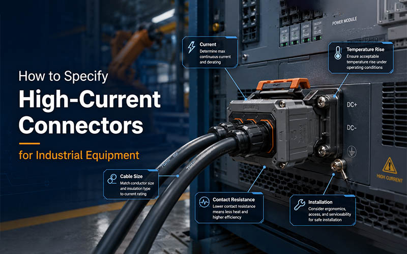
A connector is more than a simple connection point—it directly affects power transmission stability, thermal performance, installation safety, and maintenance efficiency. Below are key tips to help customers choose the right solution and understand what to look for in a reliable supplier.


1. Understand Current and Voltage Requirements

The first step in choosing an energy storage connector is defining electrical ratings:

  • Rated current and peak current capacity

  • Rated voltage level (low or high voltage systems)

  • Continuous power transmission capability

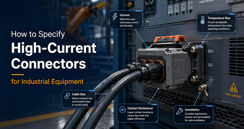
Connectors must safely handle high current loads over long operating periods without excessive temperature rise. Underrated connectors increase the risk of overheating and power loss.


2. Focus on Safety and Locking Design

Energy storage systems often operate in environments where safety is non-negotiable. Key safety features include:

  • Secure locking or anti-mis-mating design

  • Touch-proof or finger-safe contact structures

  • Reliable grounding solutions

A well-designed locking mechanism ensures stable connections during vibration, transportation, or long-term operation.


3. Consider Environmental Resistance

Energy storage installations may be exposed to:

  • Dust and humidity

  • Temperature variation

  • Outdoor or semi-outdoor conditions

Choosing connectors with appropriate IP protection levels, corrosion-resistant materials, and robust housings helps extend service life and reduce maintenance risks.


4. Evaluate Contact Materials and Conductivity

High-quality contact materials are essential for stable energy transfer. Important factors include:

  • Low contact resistance

  • High conductivity materials

  • Reliable plating for long-term performance

Good contact design improves energy efficiency and reduces heat generation during high-current operation.


5. Think About Installation and Maintenance Efficiency

In large energy storage projects, installation speed and serviceability matter. Consider:

  • Easy mating and unmating

  • Clear polarity and orientation

  • Compatibility with cable assemblies

Efficient connector design reduces installation time and simplifies future maintenance or system upgrades.


FPIC Energy Storage Connector Specifications & Advantages

With 23 years of connector and cable assembly manufacturing experience, FPIC provides energy storage connector solutions designed for real-world system demands.

Key Advantages of FPIC Energy Storage Connectors

  • Designed for high-current and stable power transmission

  • Secure and reliable connection structures

  • Durable materials suitable for long-term operation

  • Support for customized connector and cable assembly solutions

  • Stable mass production capability with strict quality control

FPIC energy storage connectors are widely used in battery energy storage systems (BESS), power distribution modules, and integrated energy solutions.


Customization Support for Energy Storage Projects

Every energy storage system has unique requirements. FPIC supports end-to-end customization, including:

  • Connector structure and pin design

  • Cable integration and harness assembly

  • Electrical and mechanical performance optimization

Our engineering team works closely with customers to ensure the connector solution fits the system, not the other way around.

energy storage connectors


Choose the Right Partner for Long-Term Reliability

Choosing the right energy storage connector is not just about specifications—it’s about choosing a manufacturer with experience, engineering capability, and production stability.

📩 Contact FPIC today to discuss your energy storage connector requirements.
We welcome inquiries and are ready to support your project from design to mass production.

industrial connectors supplier

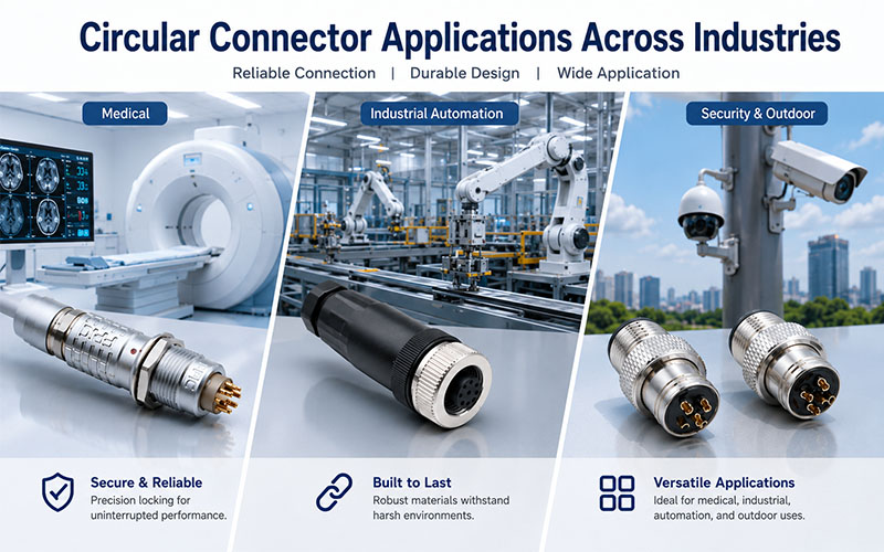
Industrial equipment demands stable, secure, and durable interconnections. At FPIC, we design and manufacture a wide range of industrial connectors to support reliable signal, data, and power transmission across complex operating environments.

With 23 years of manufacturing experience, FPIC provides both standard industrial connectors and customized interconnection solutions, helping customers meet application-specific requirements with confidence.


A Comprehensive Industrial Connector Portfolio

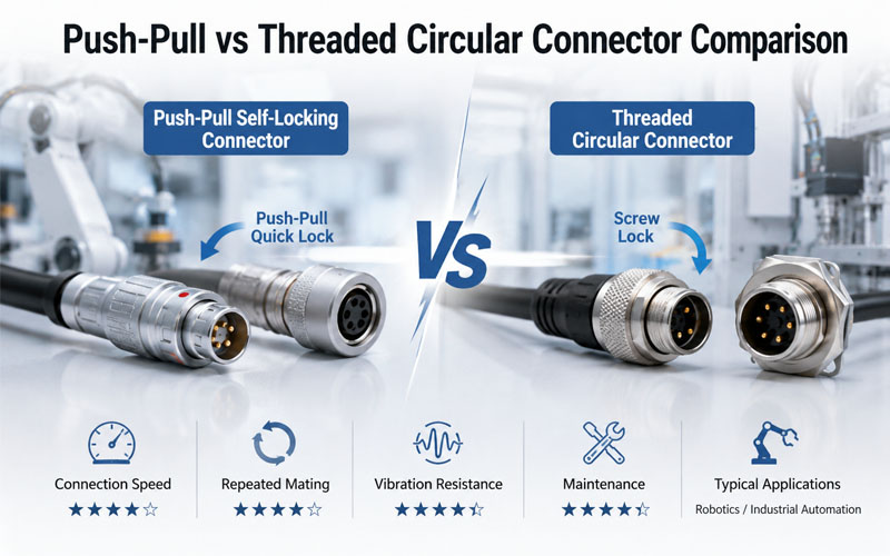
FPIC’s industrial connector series covers multiple connector types to support diverse industrial applications, including:

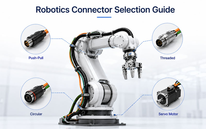
  • Circular connectors for sensors, automation, and control systems

  • Heavy-duty connectors for machinery, power distribution, and harsh environments

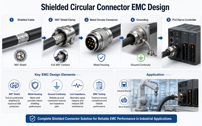
  • Metal-shell connectors offering enhanced mechanical strength and EMI protection

  • Panel-mount and cable connectors for flexible installation needs

Each connector is engineered for stable performance, secure mating, and long service life in demanding industrial conditions.

industrial connectors supplier


Designed for Harsh Industrial Environments

Industrial applications often face challenges such as vibration, dust, moisture, temperature variation, and electromagnetic interference. FPIC industrial connectors are designed to address these challenges through:

  • Robust mechanical structures

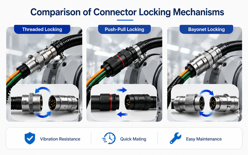
  • Reliable locking mechanisms

  • Strong resistance to vibration and wear

  • Stable electrical performance over long operating cycles

These features help ensure uninterrupted operation in automation systems, industrial machinery, and control equipment.


Customization Capabilities for Industrial Applications

Beyond standard products, FPIC specializes in customized industrial connector solutions. Our engineering team works closely with customers to develop connectors and cable assemblies tailored to specific requirements, including:

  • Custom pin configurations and layouts

  • Material selection for shells and contacts

  • Cable integration and overmolding

  • Application-specific electrical and mechanical performance

This flexibility allows customers to optimize system design while reducing assembly complexity.


Quality Manufacturing You Can Trust

FPIC operates under internationally recognized quality management systems, including ISO 9001 and IATF 16949, ensuring consistent manufacturing quality and process control.

From raw material inspection to final testing, each industrial connector undergoes strict quality checks to ensure reliability, durability, and compliance with industrial standards.


Applications Across Industries

FPIC industrial connectors are widely used in:

  • Industrial automation and robotics

  • Factory control and monitoring systems

  • Sensors and actuators

  • Industrial machinery and equipment

  • Power and signal transmission systems

Our connectors support long-term system stability in both standard and customized industrial setups.


Partner with FPIC for Industrial Connectivity

Whether you require standard industrial connectors or fully customized interconnection solutions, FPIC is ready to support your project with professional engineering, stable production capacity, and responsive service.

📩 Contact us today to discuss your industrial connector requirements and customization needs.
We welcome your inquiry.