A square pin terminal works well in standard PCB headers and low-vibration electronics. An automotive rounded pin terminal is built for stronger guidance, better vibration resistance, improved self-cleaning contact, and higher long-term reliability. If the application is automotive or high-reliability industrial equipment, the rounded automotive design is usually the better choice.
The main difference is not just the shape. Standard square pin terminals prioritize easy insertion and low cost for general electronics, while automotive rounded pin terminals are designed for vibration resistance, guided mating, stable contact, and long service life in harsher environments. Their structure, stamping process, plating method, and performance targets are all different.
If you only look at the pin tip, the difference may seem small. In real applications, though, terminal geometry affects contact stability, corrosion resistance, plating consistency, insertion feel, and even failure risk over time. This article breaks down the differences step by step so engineers, sourcing teams, and product managers can make better design decisions.
Start With the Right Terminology
Before comparing the products, it is important to use the right language.
In this article:
- Standard square pin terminal means the square or flat-edged metal pin commonly used in PCB pin headers.
- Automotive rounded pin terminal means the rounded or bullet-shaped male terminal used in automotive low-voltage connector systems.
This distinction matters because industry-leading suppliers do not treat pin headers and terminals as the same category. Aptiv’s public connection systems catalog lists Connectors, Terminals, Seals, and Pin Headers as separate product groups, which confirms that “pin header” and “automotive terminal” should not be used interchangeably.
Why This Comparison Matters
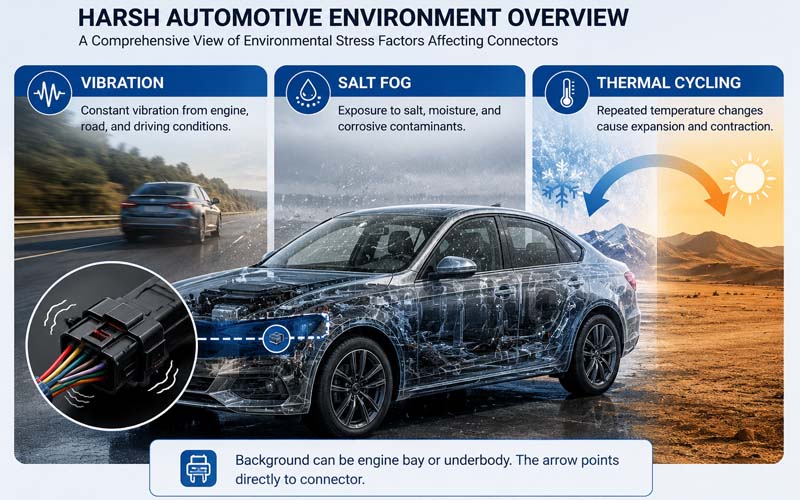
Automotive connectors work in a very different environment from ordinary board-level connectors.
According to VDA, electrical and electronic components in vehicles must continuously adapt to stricter requirements around safety, reliability, environmental exposure, vibration, temperature, and chemical resistance. VDA also highlights that wiring systems and connector components are part of that evolving standardization work.
That is why a terminal for a vehicle cannot be chosen the same way as a terminal for a simple PCB header. Even if both parts are conductive metal pins, the design priorities are different:
- Consumer electronics focus more on cost, compactness, and ease of assembly
- Automotive systems focus more on durability, vibration stability, and long-term consistency
- Harsh environments require stronger protection against debris, contact instability, plating wear, and corrosion
FPIC’s internal technical comparison document makes the same point very clearly: a standard square pin terminal is meant for lower-stress electronic connections, while the automotive rounded pin terminal is designed for high-vibration, high-reliability service conditions.
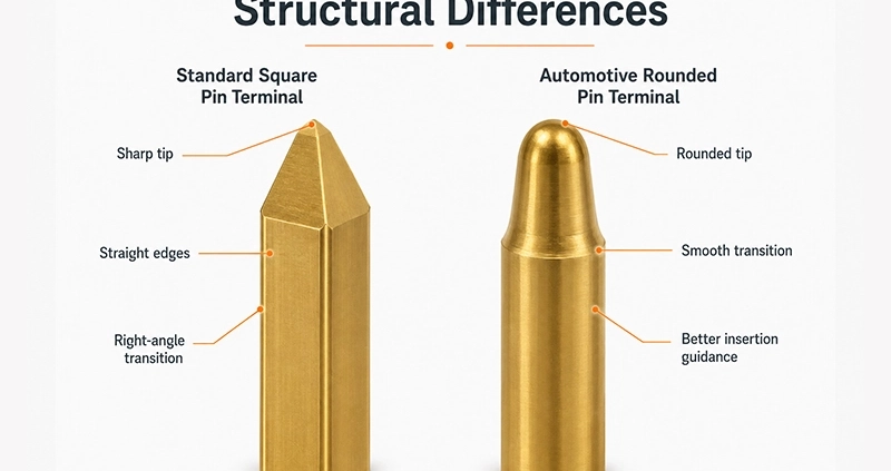
Structural Differences
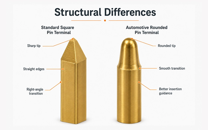
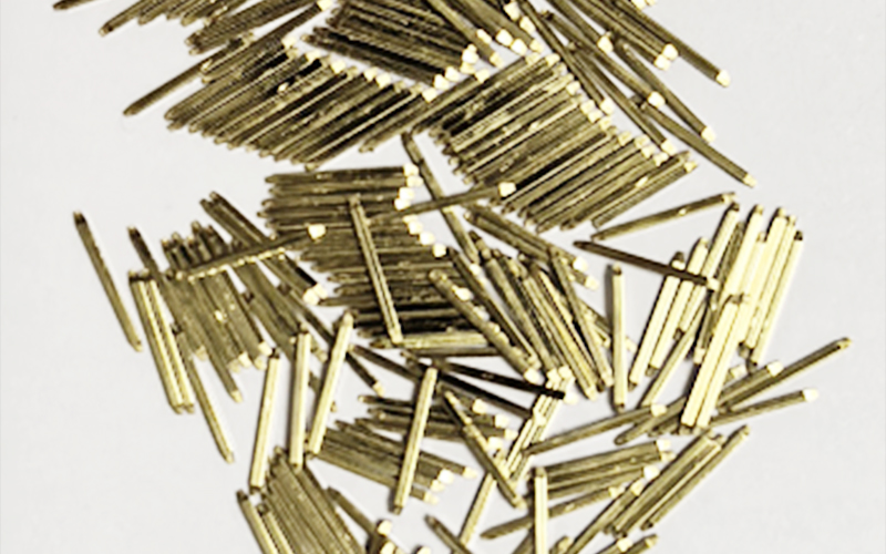
Standard Square Pin Terminals
A standard square pin terminal usually has:
- Tip: Sharp/pyramidal, small flat surface, obvious edges
- Root: 90° dead-angle
- Design focus: Easy insertion, low cost, for consumer electronics (low vibration, few insertions)
- Example applications: PCB headers, low-end electronic devices, DuPont-style wiring
This kind of structure is common in:
- Board-to-board connections
- Standard PCB headers
- Consumer electronics
- Simple control boards
- Low-vibration devices
The main benefits are easy insertion, easy manufacturing, and lower cost. But the structure also has limitations. Sharp edges and dead corners can create areas where stress concentrates, and in demanding environments they are less forgiving.
Automotive Rounded Pin Terminals
An automotive rounded pin terminal usually has:
- Tip: Rounded bullet-head / dome-shaped
- Root: Smooth tapered transition, no dead corner
- Pin body: Thicker, stronger
- Core benefits: Guided insertion, vibration resistance, self-cleaning, short-circuit protection
- Designed for automotive harsh conditions: ECU, BCM, lighting, window, seat control modules
This design offers several practical advantages:
- Better insertion guidance
- Reduced scraping at the mating interface
- More stable contact behavior
- Better vibration resistance
- Lower risk of debris staying in sharp dead corners
- Improved contact reliability over long service life
Structural Comparison Table
| Item | Standard Square Pin Terminal | Automotive Rounded Pin Terminal |
|---|---|---|
| Tip shape | Sharp / pyramidal / flat-edged | Rounded / bullet-shaped / dome-like |
| Root transition | 90° style transition, dead-corner tendency | Smooth tapered transition |
| Edge condition | Obvious corners and flat faces | Rounded surface, fewer stress points |
| Contact style | Flat or edge-dominant | Arc-guided, more stable engagement |
| Main design goal | Easy insertion, simple structure, lower cost | Guidance, vibration resistance, reliability |
| Typical environment | General electronics | Automotive low-voltage systems |
| Debris tolerance | Lower | Better |
| Reliability expectation | Basic | High |
Why Rounded Geometry Helps in Automotive Use
The rounded automotive design is not just about appearance. It changes how the terminal behaves during mating and in long-term service.
1. Better Guidance
A rounded tip helps the male terminal find its way into the mating contact more smoothly. This matters when connector tolerances, insertion angle variation, or assembly speed introduce small alignment changes.
2. Better Vibration Resistance
In vehicles, connectors see repeated vibration from engine systems, road conditions, opening and closing actions, and general operating movement. A more robust and better-guided terminal geometry helps maintain a stable contact relationship.
3. Better Self-Cleaning Behavior
When two contacts mate and unmate repeatedly, a rounded guided structure can help wipe the contact area more consistently. FPIC’s internal document specifically notes this self-cleaning advantage as one reason automotive rounded terminals better resist contamination-related issues.
4. Lower Short-Circuit Risk
The internal comparison also notes that the absence of obvious dead-angle geometry helps reduce the chance of debris buildup around the terminal root, which is one of the practical design benefits of the automotive rounded form.
Industry Background and Design Thinking
FPIC’s internal document cites historical automotive field-failure discussions as a turning point in how the industry views low-voltage terminal design. The document explains that older low-voltage connector approaches using more ordinary square-pin-like forms could create higher risk when vibration, thermal cycling, and debris were involved, which pushed the market toward more robust automotive-specific terminal geometry.
Even without repeating every historical claim, the design lesson is clear:
Automotive connectors are not just “stronger consumer connectors.” They are engineered differently because the environment is different.
That view also aligns with the broader work of VDA and USCAR, where connector systems and related specifications are continuously reviewed to meet the demands of safety, durability, and vehicle operating conditions.
Manufacturing Process Differences
The structure difference is only one part of the story. The manufacturing route is also very different.
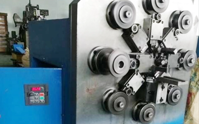
How Standard Square Pin Terminals Are Made
- Equipment: Multi-wheel forming machines
- Process: Wire extrusion → straightening → forming → cutting
- Output: Loose independent pins
- Automation: Limited
- Use case: Standard PCB headers
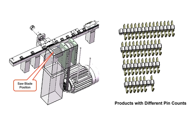
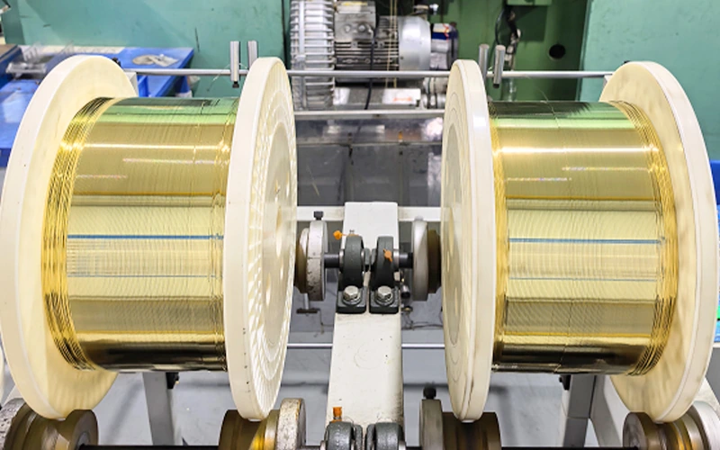
How Automotive Rounded Pin Terminals Are Made
- Equipment: High-speed precision stamping, continuous progressive dies
- Process: Brass strip → stamping → punching → bending → forming → cutting
- Output: Continuous strip carrier for automated assembly
- Automation: High compatibility, precise dimensions, supports reel-to-reel plating
Manufacturing Comparison Table
| Item | Standard Square Pin Terminal | Automotive Rounded Pin Terminal |
|---|---|---|
| Main equipment | Multi-wheel square pin forming machine | High-speed precision stamping press |
| Input material | Wire stock | Copper alloy strip |
| Core process | Extrusion/forming/cutting | Progressive stamping/forming |
| Finished form | Loose pin / independent pin | Continuous carrier strip |
| Automation compatibility | Medium | High |
| Dimensional control | Basic to medium | Higher |
| Mass-production suitability | Good for standard electronics | Better for automotive-scale process control |
Plating Process Differences
The plating route is one of the biggest technical differences, and it directly affects contact quality.
Standard Square Pin Terminal Plating
- Barrel/batch plating
- Less uniform coating; edges and tips prone to thin plating
- Manual sorting required for automation
Automotive Rounded Pin Terminal Plating
- Reel-to-reel continuous precision plating
- Uniform thickness, strong adhesion
- Fully compatible with automated assembly, injection molding, and SMT
Plating Comparison Table
| Item | Standard Square Pin Terminal | Automotive Rounded Pin Terminal |
|---|---|---|
| Workpiece form | Loose individual pins | Continuous strip terminal |
| Typical plating method | Barrel / bulk plating | Reel-to-reel precision plating |
| Thickness consistency | Lower | Higher |
| Edge coverage consistency | Less stable | Better controlled |
| Adhesion behavior | More variation | More stable |
| Automation support | Limited | Excellent |
Performance Comparison
FPIC’s internal technical comparison gives a clear picture of why automotive rounded terminals are chosen for more demanding systems.
| Metric | Square Pin | Rounded Pin |
|---|---|---|
| Contact resistance | High batch variation | Low, ≤±1mΩ |
| Mating cycles | ≤500 | >10,000 |
| Vibration resistance | Low | High, car-grade |
| Salt spray resistance | Poor | >10 years in automotive environment |
| Current carrying | Local heating | Uniform, stable temperature rise |
| Temperature tolerance | Limited | -40°C to +125°C |
| High-frequency signal | Poor | LVDS compatible, stable signal |
Industry Standards & Background
- Early Mercedes W210/W220 ECU/BCM PCB failures due to square pins → large recalls, safety issues
- USCAR / VDA / QC/T standards: automotive ≥2-pin low-voltage connectors must use rounded bullet-head terminals
- Safety, vibration, long-term reliability, and manufacturing precision are mandatory in automotive-grade terminals
Application Comparison
Best Uses for Standard Square Pin Terminals
A standard square pin terminal is usually a good fit for:
- PCB headers
- Consumer electronics
- Low-vibration control boards
- Cost-sensitive electronics
- Standard signal connections
Best Uses for Automotive Rounded Pin Terminals
An automotive rounded pin terminal is usually the better fit for:
- Automotive low-voltage systems
- Control modules
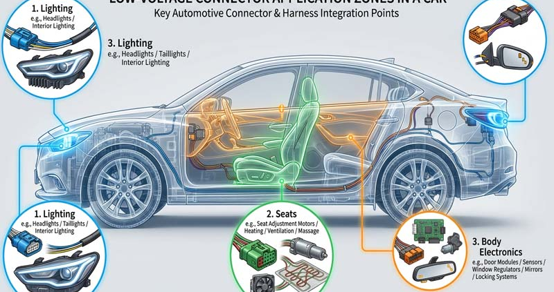
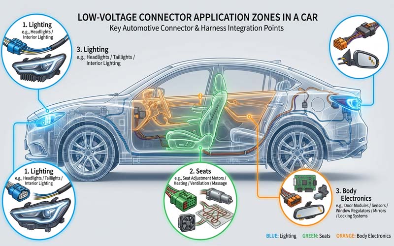
- Lighting systems
- Window lift systems
- Power seat systems
- Multimedia systems
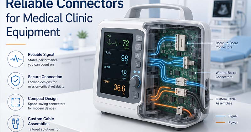
- Industrial equipment with demanding vibration requirements
- Long-life signal or low-voltage power transmission
FPIC Engineering Perspective
At FPIC, terminal selection is not treated as an isolated metal-part decision. It is part of the full connector-system design process.
A good connector terminal must be evaluated together with:
- Housing design
- Material selection
- Plating specification
- Contact force
- Current path
- Assembly process
- Testing method
- End-use environment
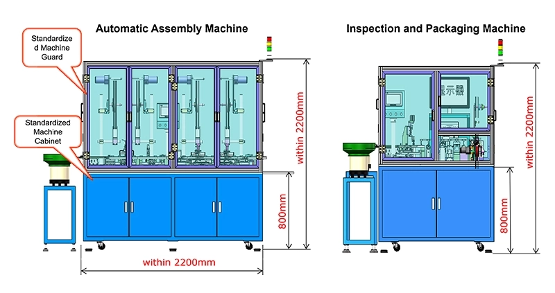
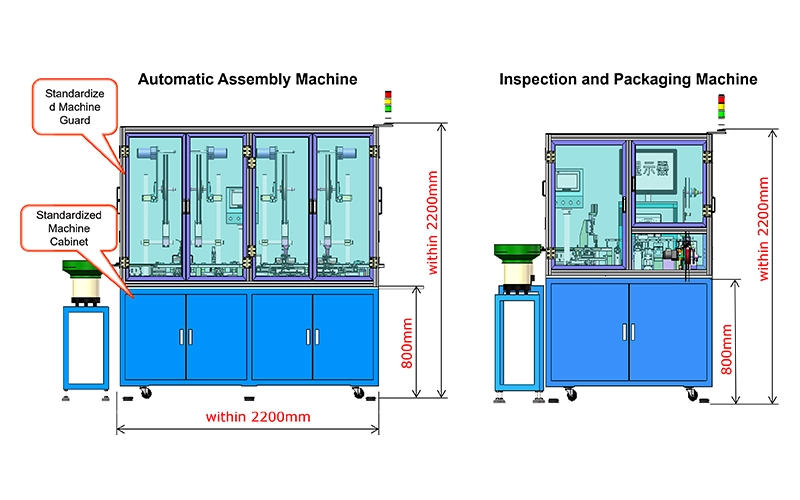
This system-level mindset also matches FPIC’s broader manufacturing strengths. According to FPIC company materials, the company supports connector development through:
- Product design and tooling development
- Metal stamping
- Plastic injection molding
- Auto assembly with CCD
- Quality assurance testing
- Automotive connector manufacturing under IATF 16949-related systems and process control
That manufacturing foundation matters because a good terminal design only delivers real value when it can also be produced consistently.
What Engineers and Buyers Should Ask Before Selecting a Terminal
When reviewing a connector concept, ask these questions:
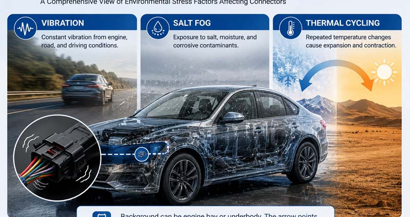
1) What is the real operating environment?
Will the connector see:
- Road vibration?
- Temperature cycling?
- Moisture?
- Corrosive conditions?
- Repeated mating?
If yes, a general square pin may not be the right solution.
2) Is insertion feel important?
Rounded automotive terminals generally provide smoother and more forgiving insertion behavior, especially when alignment is not perfect.
3) How important is long-term consistency?
If the product must stay reliable over years, especially in automotive or industrial systems, terminal geometry and plating consistency become much more important.
4) Will the part be made at scale?
If the project needs high automation, stable dimensions, and controlled plating, strip-based automotive-style terminal production has strong advantages.
Practical Selection Guide
| Application Scenario | Recommended Choice | Why |
|---|---|---|
| Standard PCB header | Standard square pin terminal | Cost-effective and suitable for simple board-level use |
| Consumer electronics | Standard square pin terminal | Enough performance for lower-stress environments |
| Automotive low-voltage connector | Automotive rounded pin terminal | Better vibration resistance and long-term reliability |
| Signal connector in harsh industrial equipment | Automotive rounded pin terminal | Better guidance and contact stability |
| High-reliability long-life design | Automotive rounded pin terminal | Better process consistency and service performance |
Conclusion
A standard square pin terminal and an automotive rounded pin terminal may look similar at first glance, but they are built for different jobs.
The square pin version is a practical choice for general electronics where cost and simplicity matter most. The automotive rounded version is designed for a tougher world: vibration, temperature change, longer service life, and higher reliability requirements.
So if the project is automotive, or if the application behaves more like automotive in terms of durability demands, the safer decision is usually the automotive rounded terminal.
FAQ
1. Is a pin header the same as an automotive terminal?
No. A pin header usually refers to a connector category used on PCBs, while an automotive terminal refers to a terminal system designed for vehicle-grade electrical connection. Leading supplier catalogs treat them as separate categories.
2. Why are automotive terminals often rounded?
Because the rounded shape improves insertion guidance, reduces sharp-edge stress, supports more stable mating, and performs better in vibration-heavy environments.
3. Are square pin terminals bad?
Not at all. They are a good solution for the right application. The issue is not quality, but fit. They are simply intended for less demanding operating conditions than automotive terminals.
4. Does plating really make a big difference?
Yes. Plating consistency affects contact resistance, corrosion resistance, wear behavior, and long-term performance. Reel-to-reel precision plating generally offers better consistency for automotive terminals.
5. When should I choose the automotive rounded design?
Choose it when the connector must survive vibration, repeated mating, wider temperature exposure, and longer service life requirements.
Ready to choose the right terminal for your automotive or industrial application?
Explore FPIC’s complete range of low-voltage automotive connectors and bullet-head terminals for high-reliability, vibration-resistant, and long-life performance.
View Products: https://fpiconn.com/products/
Contact Sales: info@fpiconn.com
💡 Tip: Our engineering team can help you select the right terminal and connector solution for your exact application, including rapid prototyping and mass-production guidance
Resources
- FPIC Internal Technical Document: “Differences Between Automotive Low-Voltage Connector Terminals and Standard Pin Header Terminals”
This internal FPIC source provided the core technical comparison for structure, process route, plating method, performance differences, and application recommendations used in this article. - Aptiv – Connection Systems Catalog
Aptiv’s official catalog clearly separates Terminals and Pin Headers into different product categories, which supports the terminology distinction used in this article.
Link: https://www.aptiv.com/en/solutions/connection-systems/catalog - VDA – Electrical/Electronic Components and General System Requirements
VDA explains that automotive electrical and electronic components must continuously adapt to requirements involving safety, reliability, vibration, temperature, chemicals, and other operating conditions.
Link: https://www.vda.de/en/topics/automotive-industry/standardization-and-technical-standards/e-e-components-and-general-system-requirements - USCAR – EWCAP / Connector Validation Context
USCAR materials help show the broader North American automotive context for connector and terminal validation work.
Link: https://uscar.org/