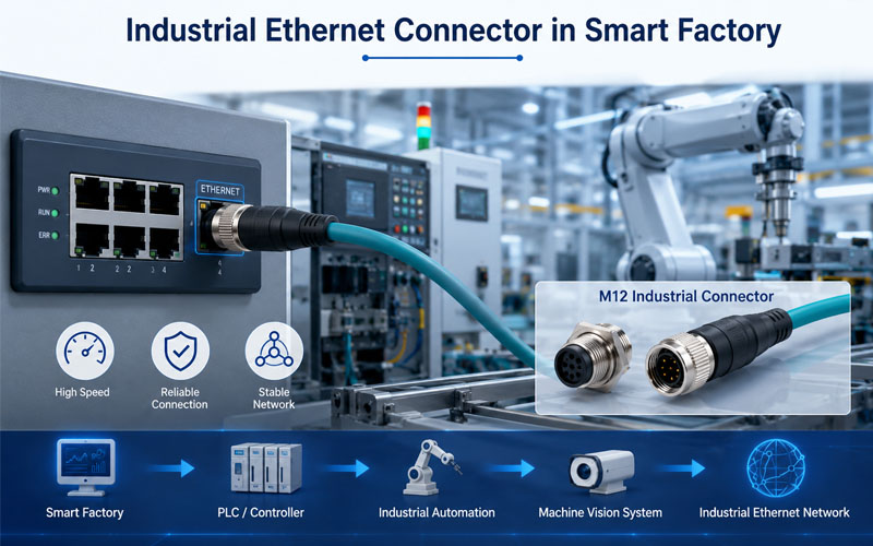
Industrial Ethernet Connector in Smart Factory

Industrial Ethernet has become the communication backbone of modern automation systems. Protocols such as EtherCAT, PROFINET, EtherNet/IP, and Modbus TCP connect PLCs, servo drives, robots, machine vision systems, and distributed I/O with high-speed, real-time data exchange.

As communication speeds continue to increase, engineers often focus on bandwidth, cable category, and protocol compatibility. However, one equally important factor is frequently overlooked—mechanical stability.

Even a connector capable of supporting Gigabit Ethernet can experience intermittent communication if vibration, repeated movement, or unstable contact compromises the physical connection.

This article explores why connector mechanical design is just as important as transmission speed for reliable Industrial Ethernet performance.

Industrial Ethernet Connector in Smart Factory


High-Speed Communication Depends on Stable Physical Connections

Industrial Ethernet transmits high-frequency differential signals that are far more sensitive than conventional power circuits.

Any variation in contact pressure or electrical continuity can negatively affect communication quality.

Poor mechanical stability may result in:

  • Packet loss
  • Increased bit error rate
  • Network reconnection
  • Communication interruptions
  • Unexpected production downtime

For high-speed industrial networks, electrical performance begins with a mechanically reliable connection.


Industrial Environments Are Constantly Moving

Unlike office networks, industrial Ethernet connectors operate under continuous mechanical stress.

Typical sources include:

  • Robot arm acceleration
  • Servo motor vibration
  • Conveyor movement
  • Machine tool impacts
  • AGV and AMR motion
  • Continuous drag chain movement

These conditions can gradually loosen poorly designed connectors or reduce contact stability over time.

Connector reliability must therefore be evaluated under real operating conditions rather than laboratory environments.


Locking Mechanisms Improve Network Reliability

One of the primary functions of an Industrial Ethernet connector is preventing accidental disconnection.

Common locking mechanisms include:

Threaded Locking

Advantages:

  • Excellent vibration resistance
  • High mechanical retention
  • Suitable for permanent installations

Typical applications:

  • Servo systems
  • CNC machines
  • Heavy industrial equipment

Push-Pull Locking

Advantages:

  • Fast installation
  • One-handed operation
  • Secure self-locking
  • Reduced maintenance time

Typical applications:

  • Robotics
  • Medical equipment
  • Automated production lines

Bayonet Locking

Advantages:

  • Quick quarter-turn connection
  • Reliable positioning
  • Good mechanical security

Typical applications:

  • Mobile machinery
  • Outdoor automation
  • Portable industrial equipment

Selecting the correct locking mechanism helps maintain stable Ethernet communication while simplifying maintenance.


Contact Stability Directly Affects Signal Integrity

Industrial Ethernet connectors must maintain consistent electrical contact despite vibration and repeated movement.

Important design factors include:

  • Contact spring design
  • Contact force
  • Gold-plated contacts
  • Precision machining
  • Stable insertion force

High-quality contacts minimize fluctuations in resistance and help preserve signal integrity over long operating periods.


Shielding Is More Than EMI Protection

Industrial environments contain numerous sources of electromagnetic interference, including:

  • Variable frequency drives
  • Servo amplifiers
  • Switching power supplies
  • High-current power cables

Shielded connectors provide:

  • Reduced electromagnetic interference
  • Better signal integrity
  • Stable high-speed communication
  • Lower communication error rates

For maximum EMC performance, connector shielding should include continuous 360° shield termination between the cable braid and the connector housing.


Environmental Protection Supports Long-Term Reliability

Industrial Ethernet connectors are often exposed to:

  • Dust
  • Oil
  • Coolant
  • Moisture
  • Metal particles
  • Cleaning chemicals

Appropriate IP ratings help maintain connector performance in harsh environments.

Typical protection levels include:

IP RatingTypical Application
IP67Industrial automation and robotics
IP68Outdoor automation and renewable energy
IP69KFood processing and washdown equipment

Environmental sealing protects both electrical contacts and communication reliability.


Validation Beyond Data Speed

A connector should never be selected based solely on its data rate specification.

Comprehensive validation should include:

  • Vibration testing
  • Mechanical shock testing
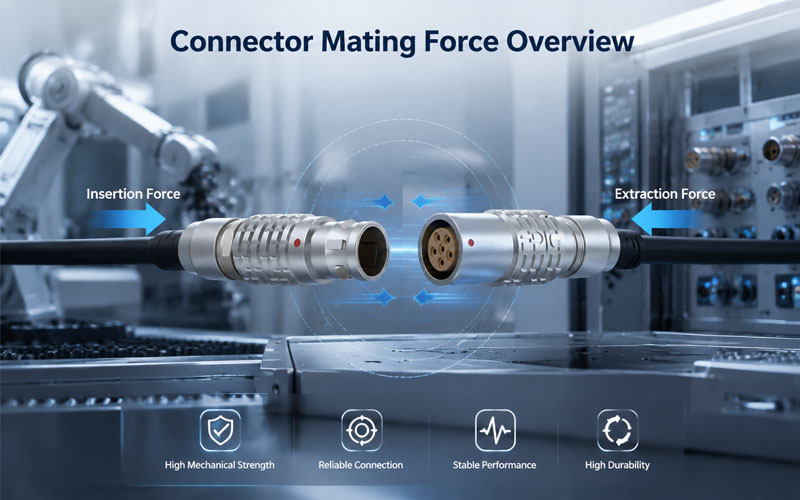
  • Mating cycle testing
  • Contact resistance measurement
  • EMC testing
  • Cable flex testing
  • Environmental sealing verification

Testing complete cable assemblies under real operating conditions provides the most reliable performance assessment.


How FPIC Supports Industrial Ethernet Connectivity

FPIC develops high-performance circular connectors, push-pull self-locking connectors, waterproof connectors, and customized connector assemblies for Industrial Ethernet applications.

Our solutions are engineered to provide reliable locking, stable electrical contacts, effective EMC shielding, and long-term durability for robotics, factory automation, machine vision, servo systems, and intelligent manufacturing equipment. With over 23 years of manufacturing experience, FPIC supports customers from design optimization to mass production.


Final Thoughts

Industrial Ethernet performance depends on far more than bandwidth specifications.

Mechanical stability, secure locking, contact reliability, shielding, and environmental protection all contribute to long-term communication performance.

As factories become increasingly connected and automated, connector design plays a vital role in reducing downtime, maintaining stable network communication, and ensuring reliable operation throughout the equipment lifecycle.


FAQ

Why is mechanical stability important for Industrial Ethernet connectors?

Mechanical stability ensures consistent electrical contact under vibration, motion, and shock, reducing communication interruptions and network failures.

Which locking mechanism is best for Industrial Ethernet?

The best locking mechanism depends on the application. Threaded connectors provide excellent vibration resistance, while push-pull connectors offer faster maintenance and secure self-locking.

Do Industrial Ethernet connectors require shielding?

Yes. Shielded connectors help reduce electromagnetic interference (EMI), improve signal integrity, and support reliable high-speed communication.

What IP rating is recommended for Industrial Ethernet connectors?

IP67 is suitable for many factory automation applications, while IP68 or IP69K may be required for outdoor or washdown environments.

How should Industrial Ethernet connectors be tested?

Recommended tests include vibration, EMC, contact resistance, mating cycles, cable flex, mechanical shock, and environmental sealing.


Looking for Reliable Industrial Ethernet Connector Solutions?

FPIC provides high-performance circular connectors, push-pull self-locking connectors, and customized Industrial Ethernet connectivity solutions for robotics, factory automation, machine vision, and intelligent manufacturing. Our engineering team helps customers achieve reliable communication through robust mechanical design, effective shielding, and application-specific connector solutions.

Contact FPIC today to discuss your Industrial Ethernet connector requirements.


Resources

  1. IEC 61076 – Connectors for Electrical and Electronic Equipment
    https://webstore.iec.ch/
    International standards covering the design, testing, and performance of industrial and circular connectors.
  2. IEC 61158 – Industrial Communication Networks (Fieldbus Specifications)
    https://webstore.iec.ch/
    Defines communication standards widely used in industrial Ethernet and automation networks.
  3. ODVA – EtherNet/IP Technology Overview
    https://www.odva.org/
    Provides technical guidance on EtherNet/IP architecture, industrial networking, and physical connectivity.
  4. PROFIBUS & PROFINET International (PI)
    https://www.profibus.com/
    Offers technical resources for PROFINET communication, connector requirements, and industrial networking best practices.
  5. Phoenix Contact – Industrial Ethernet Connectivity Solutions
    https://www.phoenixcontact.com/
    Provides engineering resources on Industrial Ethernet connectors, shielding, and reliable network infrastructure.

Smaller electronic systems increasingly combine high-speed signals, wireless functions, power conversion, sensors, and control circuits on densely populated PCBs. Under these conditions, connector selection affects more than pin count and mating height.

A compact connector must also support signal integrity, current delivery, mechanical stability, manufacturability, and electromagnetic compatibility.

Quick Answer:

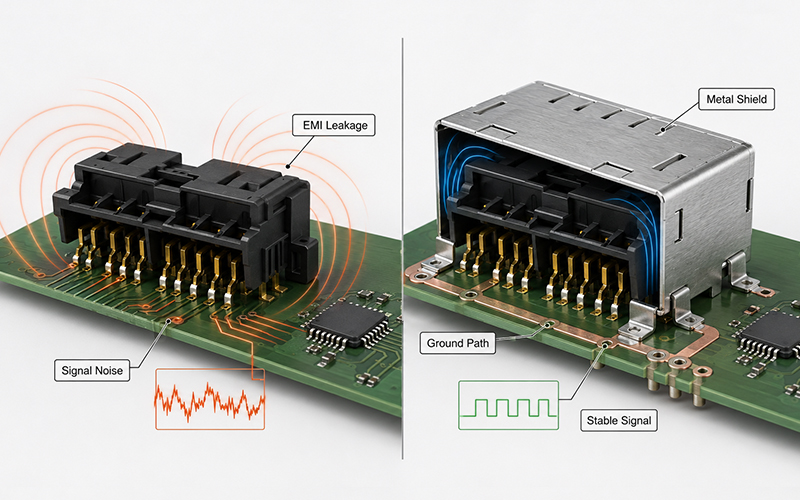
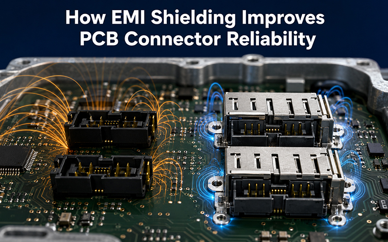
EMI shielding improves PCB connector reliability by limiting electromagnetic energy entering or leaving the connection interface. An effective shield, combined with a low-impedance grounding path and correct PCB layout, can reduce noise, crosstalk, data errors, and EMC compliance risks.

Molex’s recent Quad-Row Shield announcement illustrates this industry direction. The connector combines a four-row contact layout with an integrated metal shield. Molex reports up to a 25 dB EMI reduction compared with its unshielded Quad-Row version, while samples are available for custom inquiries and commercial supply is planned for the second quarter of 2026.

However, a metal cover alone does not guarantee reliable electromagnetic performance. Engineers must evaluate the connector, PCB grounding, enclosure, contact layout, cable paths, power distribution, and application environment as one system.


Why EMI Becomes More Difficult in Compact PCB Systems

Miniaturization places more electrical functions into a smaller physical area. Signal traces, power contacts, antennas, switching regulators, clocks, processors, sensors, and communication circuits may operate only millimeters apart.

This creates several potential interference paths:

  • noise generated by switching power circuits;
  • radiation from high-speed digital signals;
  • coupling between adjacent contacts;
  • interference entering through openings in an enclosure;
  • current flowing through poorly controlled ground paths;
  • transient noise from motors, relays, converters, or wireless transmitters.

A conventional connector may provide adequate electrical continuity while still allowing interference to couple across the board interface.

This is particularly important when the system includes:

  • high-speed serial communication;
  • cameras or display modules;
  • radar or wireless functions;
  • compact automotive control modules;
  • medical or measuring equipment;
  • industrial sensors and controllers;
  • mixed power-and-signal interfaces.

Molex identifies controlled impedance, reduced crosstalk, and EMI shielding as important features for optimizing PCB layout, signal integrity, and system performance in mezzanine connectors.

What EMI Shielding Does at the Connector Interface

A connector shield forms a conductive barrier around or near the signal contacts. When properly grounded, this structure helps control electromagnetic fields around the mating interface.

Its primary functions include:

What EMI Shielding Does at the Connector Interface

1. Reducing Radiated Emissions

Fast signal edges and switching currents can cause the connector and adjacent PCB structures to radiate electromagnetic energy.

A conductive shield helps contain part of this energy before it reaches nearby circuits, antennas, sensors, or the external environment.

2. Improving Immunity to External Noise

The same barrier can reduce the amount of external interference that reaches sensitive contacts.

This becomes important when connectors operate near:

  • DC/DC converters;
  • motors and actuators;
  • wireless antennas;
  • high-current conductors;
  • relays and solenoids;
  • vehicle power electronics.

3. Controlling Crosstalk

Crosstalk occurs when energy from one signal path couples into another.

Shielding can reduce field coupling, but pin assignment, contact spacing, ground-contact placement, differential-pair routing, and return-path design remain equally important.

4. Supporting EMC Compliance

Integrated shielding may simplify the path toward electromagnetic compatibility because it controls interference closer to the source.

Molex states that its shielded Quad-Row design can reduce EMI, support stringent EMI/EMC requirements, and lower the regulatory testing burden. This is a supplier-reported product benefit rather than a guarantee that any completed device will pass certification automatically.

The complete product must still be tested in its final configuration.


Shielding Effectiveness Depends on the Ground Path

One of the most common design errors is treating the metal shield as an isolated component.

A shield only works effectively when interference current can flow through a controlled, low-impedance path to ground or chassis.

Engineers should examine:

  • how the shield contacts the PCB;
  • the number and location of grounding points;
  • the length of the grounding path;
  • PCB ground-plane continuity;
  • enclosure contact around the interface;
  • gaps between mating shield components;
  • whether the shield remains continuous after mating.

At higher frequencies, a long or narrow grounding path can behave inductively. This limits the shield’s effectiveness even when DC continuity appears satisfactory.

For this reason, shielding design should begin during connector and PCB development—not after the first EMC test failure.

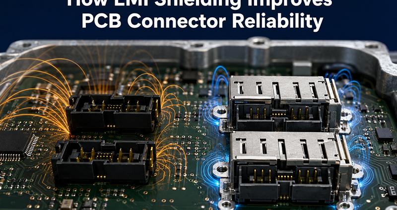
How EMI Shielding Improves PCB Connector Reliability

EMI Shielding and Signal Integrity Are Related but Different

EMI and signal integrity are closely connected, but they are not identical.

EMI design controls unwanted electromagnetic energy entering or leaving a system.

Signal-integrity design ensures that the intended signal reaches the receiver with acceptable timing, amplitude, noise margin, and waveform quality.

A shield may reduce external noise while the signal still suffers from:

  • impedance discontinuity;
  • reflections;
  • poor return paths;
  • excessive insertion loss;
  • skew between differential traces;
  • crosstalk inside the contact field.

For high-speed interfaces, engineers may need to evaluate:

  • insertion loss;
  • return loss;
  • near-end and far-end crosstalk;
  • differential impedance;
  • S-parameters;
  • eye-diagram performance;
  • contact assignment and grounding strategy.

Molex states that preferred pin layouts and S-parameter input specifications may be assigned within the 80-pin Quad-Row Shield design. This shows that shielding and contact mapping must be engineered together rather than evaluated separately.


Miniaturization Must Not Reduce Power Reliability

Modern compact connectors increasingly carry both signal and power.

This creates a difficult design balance:

  • more contacts in less PCB area;
  • higher current density;
  • less space for heat dissipation;
  • greater sensitivity to contact resistance;
  • stronger interaction between power noise and signal circuits.

Molex describes its Quad-Row architecture as supporting up to 80 pins and substantially more signal and power connections than a single-pin interface. Its product page lists current capability in the approximate 2.6–3.0 A-per-contact range for typical configurations, while the wider Molex board-to-board portfolio includes different product families for substantially higher current requirements.

This does not mean every contact can carry the maximum value simultaneously under all conditions.

Current capability depends on:

  • conductor and terminal geometry;
  • number of simultaneously energized contacts;
  • contact resistance;
  • ambient temperature;
  • PCB copper area;
  • enclosure airflow;
  • duty cycle;
  • permitted temperature rise.

When power and sensitive signals share one interface, engineers should consider using dedicated ground contacts, separating power from high-speed pairs, and validating the final assembly through temperature-rise and electrical testing.


When Does a PCB Connector Need EMI Shielding?

Not every application requires a shielded interface.

Adding shielding can increase component complexity, tooling requirements, PCB grounding needs, and cost. It should therefore solve a defined electromagnetic problem.

Shielding deserves serious consideration when one or more of the following conditions apply.

1. High-Speed Signals Cross the Interface

Interfaces carrying high-speed differential data, camera signals, displays, radar data, Ethernet, or other fast digital communication are more sensitive to discontinuities and interference.

2. The Connector Is Close to a Noise Source

Risk increases when the connector sits near switching regulators, high-current traces, motors, relays, inverters, wireless transmitters, or inductive loads.

3. The Product Has Limited Enclosure Shielding

A plastic enclosure or a large opening around the connector may offer little control over radiated energy.

An integrated connector shield can help close part of this electromagnetic gap.

4. The System Has Strict EMC Requirements

Automotive, industrial, medical, aerospace, and communication equipment often face demanding immunity and emission requirements.

A shielded interface may provide additional design margin, although system-level testing remains necessary.

5. Power and Signal Contacts Share Limited Space

Mixed power-and-signal layouts may introduce switching noise, ground bounce, and thermal constraints.

Shielding can be part of the solution, but contact allocation and PCB return-path design are equally important.


Connector Shielding Cannot Correct a Poor PCB Layout

A shielded component may still perform poorly when the surrounding PCB layout creates uncontrolled interference paths.

Engineers should coordinate the connector design with the board layout.

1. Maintain a Continuous Reference Plane

High-speed signals need a stable return path.

Avoid unnecessary ground-plane splits beneath the connector and around the signal escape region.

2. Place Ground Connections Close to the Shield

Short, wide ground connections generally provide lower impedance than long, narrow traces.

Multiple grounding points may improve current distribution and reduce shield discontinuities.

3. Separate Sensitive Signals from Noisy Power Paths

Avoid routing sensitive differential pairs next to switching nodes, inductors, motor outputs, or high-current conductors.

4. Minimize Stubs and Abrupt Geometry Changes

Unused branches, long breakout paths, and sudden changes in trace width or reference plane can increase reflection and noise.

5. Coordinate PCB and Enclosure Grounding

The connector shield, board ground, chassis, and external enclosure should follow a deliberate grounding strategy.

Connecting them without understanding the return-current path can create new coupling problems.

Mechanical Design Also Affects Shielding Reliability

Connector shielding must remain effective after assembly, vibration, temperature cycling, and repeated mating.

A mechanically weak shield may lose contact pressure, deform, or create gaps that reduce electromagnetic performance.

Important mechanical considerations include:

  • shield retention in the housing;
  • mating alignment;
  • solder-joint strength;
  • board hold-down features;
  • resistance to connector peeling or lifting;
  • vibration and shock resistance;
  • durability over the required mating cycles;
  • protection against handling damage.

Molex uses an armored, insert-molded nail and internal cover in its Quad-Row family to improve mechanical robustness and reduce mating damage. The company also states that the design supports conventional SMT production and high-volume reel packaging.

For automotive and industrial applications, the connector design may also need to consider:

  • temperature cycling;
  • vibration;
  • contamination;
  • housing retention;
  • pin position and coplanarity;
  • solder-joint fatigue;
  • long-term contact-force stability.

Materials and Plating Influence Electrical Performance

Shield performance depends partly on material conductivity, surface condition, mechanical force, and corrosion resistance.

The signal contacts and shield may use different base materials and plating systems according to their functions.

Typical engineering considerations include:

  • electrical conductivity;
  • spring force;
  • formability;
  • wear resistance;
  • solderability;
  • corrosion protection;
  • contact resistance;
  • compatibility with SMT temperatures.

FPIC’s technical materials identify connector contacts and shield-related parts made from copper alloys, stainless steel, and other stamped materials, with plating selected according to conductivity, solderability, corrosion resistance, and cost. They also describe high-temperature polymers such as LCP, PA9T, PA6T, PA46, and PPS for connector applications that must tolerate reflow processing.

Material selection should therefore reflect the complete production and operating environment, not only the connector’s nominal electrical rating.

How Shielded PCB Connectors Should Be Validated

A shielded connector requires more than a dimensional inspection.

Validation should combine electromagnetic, electrical, mechanical, environmental, and manufacturing checks.

Electromagnetic Evaluation

Depending on the project, testing may include:

  • shielding-effectiveness comparison;
  • radiated emissions;
  • conducted emissions;
  • radiated immunity;
  • bulk-current injection;
  • electrostatic discharge;
  • S-parameter characterization;
  • crosstalk and signal-integrity testing.

Electrical Evaluation

Common checks include:

  • contact resistance;
  • insulation resistance;
  • dielectric withstand voltage;
  • current-carrying capacity;
  • voltage drop;
  • temperature rise.

Mechanical Evaluation

Relevant tests may include:

  • mating and unmating force;
  • terminal retention;
  • connector hold-down strength;
  • vibration;
  • mechanical shock;
  • mating durability.

Environmental Evaluation

Depending on the application:

  • thermal cycling;
  • high- and low-temperature exposure;
  • humidity;
  • salt spray;
  • solder-heat resistance;
  • contamination or cleanliness inspection.

Manufacturing Evaluation

For SMT board connectors, engineers should also monitor:

  • pin coplanarity;
  • terminal position;
  • solder-joint geometry;
  • reflow compatibility;
  • pick-and-place handling;
  • shield deformation;
  • automated optical or CCD inspection.

FPIC’s internal capability materials list contact-impedance testing, temperature-rise testing, withstand-voltage and insulation testing, insertion and extraction testing, vibration, thermal shock, X-ray inspection, Keyence dimensional measurement, solder-heat evaluation, and CCD-supported automated production.

These capabilities help support design verification, but the final validation plan should always follow the customer’s application, product specification, and applicable standards.


A Practical Selection Checklist

Before choosing or developing a shielded PCB connector, define the following requirements.

Design areaInformation to confirm
Interface typeBoard-to-board, wire-to-board, header, mezzanine, or hybrid
Contact layoutPin count, pitch, row arrangement, and pin assignment
Signal requirementsProtocol, data rate, impedance, and differential pairs
Power requirementsVoltage, current per circuit, and active-contact count
Shielding objectiveEmissions, immunity, crosstalk, or enclosure continuity
GroundingPCB ground points, chassis path, and shield termination
Mechanical layoutMating height, orientation, retention, and alignment
EnvironmentTemperature, vibration, humidity, dust, and corrosion
ProductionSMT process, reflow profile, packaging, and inspection
ValidationSI, EMC, electrical, mechanical, and environmental tests

A complete requirement set prevents a project from being reduced to “same pitch, same pin count.”

Two connectors with similar dimensions may perform very differently when shielding continuity, current density, material selection, solder-joint strength, and high-speed layout are considered.


How FPIC Supports Custom PCB Connector Development

FPIC develops board-to-board, wire-to-board, automotive PCB header, receptacle, terminal, shielding, and custom interconnection components.

For compact PCB connector projects, engineering support can include:

  • application and drawing review;
  • pitch, pin-count, and mating-height evaluation;
  • contact and housing design;
  • shielding-cover and stamped-metal development;
  • signal and power contact allocation;
  • material and plating selection;
  • precision stamping and insert molding;
  • injection-mold and stamping-tool development;
  • SMT and reflow compatibility review;
  • dimensional, electrical, and mechanical verification;
  • automated assembly and CCD inspection;
  • prototype and scalable production support.

FPIC’s internal connector materials describe board-to-board products ranging from conventional pin headers to fine-pitch, high-density interfaces. They also identify applications combining high-speed signals, lower-speed circuits, and power distribution within one interface.

For automotive projects, FPIC operates under IATF 16949 and supports automotive PCB and low-voltage connector development for applications such as lighting control, power seats, window systems, multimedia modules, and related electronic control assemblies. Its broader manufacturing platform includes in-house tooling, stamping, injection molding, insert molding, automated assembly, testing, and precision-component production.

FPIC does not position every custom PCB connector as an off-the-shelf shielded high-speed product. Instead, shielding, signal performance, current capability, dimensions, materials, and validation requirements should be defined during project review.


Frequently Asked Questions

Does every board-to-board connector need EMI shielding?

No. Shielding is most valuable when high-speed signals, sensitive electronics, strong nearby noise sources, limited enclosure shielding, or strict EMC requirements create a measurable interference risk.

Can a metal connector cover guarantee EMC compliance?

No. It may improve electromagnetic performance, but final compliance depends on PCB layout, grounding, enclosure design, cables, software operating modes, power circuits, and the complete assembled product.

Does shielding improve signal integrity?

It can reduce external interference and coupling, but it cannot correct impedance discontinuities, poor differential routing, excessive loss, or an interrupted return path.

Can power and signal contacts share the same connector?

Yes, provided the contact layout, current density, temperature rise, grounding, isolation, and signal-integrity requirements are properly engineered and validated.

What information is needed for a custom shielded connector?

Provide the 2D or 3D drawings, PCB layout constraints, pitch, pin count, mating height, signal protocol, current requirements, shielding target, grounding concept, production volume, and required tests.


Conclusion

EMI shielding is becoming a functional part of compact connector design rather than an optional metal accessory.

A reliable shielded interface must combine electromagnetic control with suitable grounding, signal mapping, current capacity, thermal performance, mechanical retention, materials, SMT compatibility, and system-level validation.

For equipment manufacturers, the best connector is not simply the smallest one. It is the interface that uses limited PCB space without compromising signal quality, power delivery, production consistency, or long-term reliability.

Discuss Your Custom PCB Connector Project

FPIC supports customized automotive PCB headers, board-to-board connectors, terminals, shielding components, and complete interconnection development.

Send your drawings, PCB constraints, electrical requirements, application conditions, and forecast demand for engineering review.

Email: info@fpiconn.com


Resources

  • Molex. Molex Announces Availability of Industry-First Space-Saving Quad-Row Board-to-Board Connectors with EMI Shields. November 4, 2025.
  • Molex. Quad-Row Connectors—Features, Specifications and Applications.
  • Molex. Mezzanine Connectors.
  • Molex. Board-to-Board Connectors.
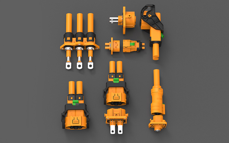
High-current connector used in BESS cabinet energy storage system

Introduction

Battery energy storage systems (BESS) are rapidly expanding as global demand for grid stability and renewable integration increases.

In modern BESS cabinet architecture, high-current connectors are no longer secondary components—they directly influence system safety, thermal behavior, installation efficiency, and long-term reliability.

For engineers and system integrators, connector selection has become a key design decision rather than a simple component choice.

The Role of High-Current Connectors in BESS Systems

High-current connectors serve as the critical electrical interface between battery modules, busbars, and power distribution units inside a BESS cabinet.

Their performance affects:

  • Current transmission stability
  • Temperature rise under load
  • System insulation safety
  • Installation efficiency
  • Maintenance accessibility

A weak connection point can become the limiting factor of an otherwise well-designed energy storage system.


Why Current Rating Alone Is Not Enough

Many connector selections are based only on rated current and voltage. However, in real BESS applications, this is not sufficient.

Engineering considerations must also include:

  • Contact resistance stability over time
  • Heat dissipation in confined cabinet spaces
  • Mechanical locking reliability
  • Mating cycle durability
  • Assembly consistency in mass production

In high-density energy storage systems, thermal behavior and connection stability are often more critical than nominal electrical ratings.


Thermal Stability and System Safety

One of the most important risks in BESS cabinet design is localized heating at connection points.

If contact resistance is unstable:

  • Heat accumulation increases
  • Insulation aging accelerates
  • Nearby components may be affected
  • System reliability decreases over time

Properly engineered high-current connectors help maintain stable thermal performance under continuous load, reducing long-term system risk.


Installation Efficiency and Manufacturing Impact

BESS systems are increasingly built in modular and scalable architectures.

High-current connectors can significantly improve:

  • Cabinet assembly speed
  • Cable routing efficiency
  • Reduction of wiring errors
  • Standardization of production processes

For large-scale energy storage deployment, even small improvements in installation efficiency can translate into major cost and time savings.


Maintenance and Lifecycle Considerations

Energy storage systems are long-life assets.
Therefore, maintainability is a critical design factor.

A well-designed connector system supports:

  • Easy replacement of modules
  • Clear mating orientation
  • Reduced risk of incorrect reconnection
  • Faster service operations

This directly impacts total lifecycle cost and system uptime.


FPIC Energy Storage Connector Capability

FPIC develops high-current connector solutions for energy storage and battery system applications, including:

These solutions are designed for BESS cabinet, battery module, and power distribution applications.

High-current connector used in BESS cabinet energy storage system


Application Areas

FPIC high-current connectors are suitable for:


Conclusion

As BESS systems scale in power density and deployment volume, connector design becomes a fundamental part of system engineering.

High-current connectors are no longer just electrical accessories—they are core components that influence safety, efficiency, and system lifecycle performance.

Selecting the right connector early in the design stage helps ensure a more reliable and scalable energy storage solution.


Contact FPIC

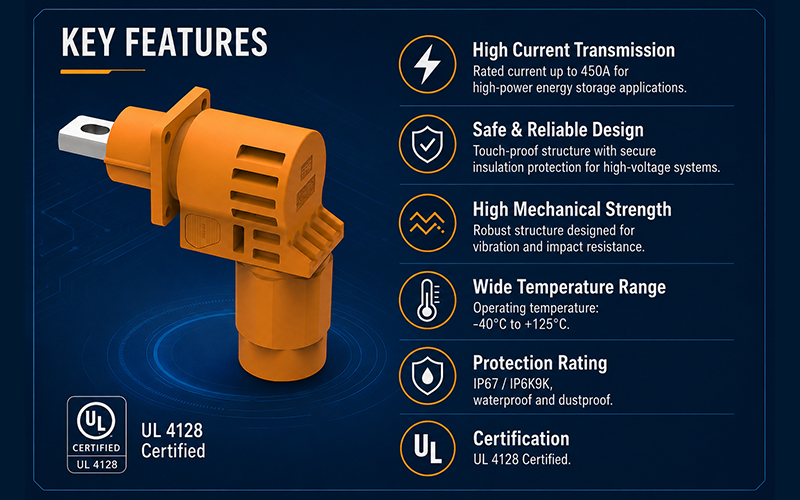
For energy storage connector development or 450A / 2000V high-current applications, FPIC provides engineering support and customized connector solutions.

Website: https://fpiconn.com/
Email: info@fpiconn.com


FAQ

1. What is a high-current connector used for in BESS?

It is used to connect battery modules, busbars, and power distribution systems inside energy storage cabinets.

2. Why are high-current connectors important in energy storage systems?

They affect thermal performance, safety, installation efficiency, and long-term system reliability.

3. Is current rating enough when selecting a connector for BESS?

No. Contact resistance, thermal behavior, and mechanical stability are equally important.

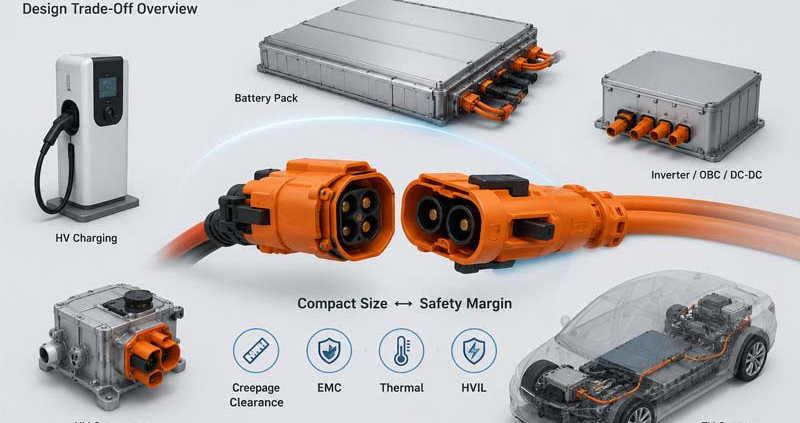
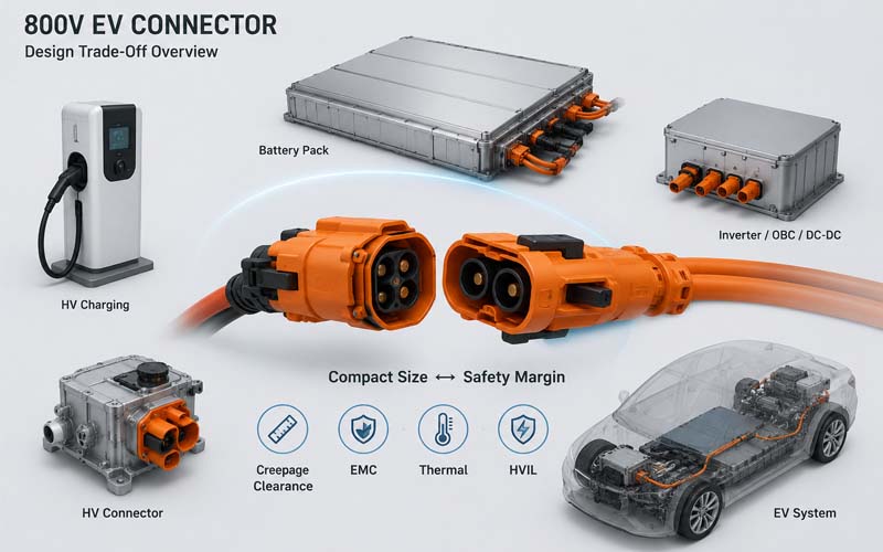
800V EV CONNECTOR Design Trade-Off Overview

The transition from 400V to 800V vehicle architectures is reshaping the design of high-voltage connector.

Automakers are adopting 800V systems to support:

  • faster charging
  • higher power density
  • improved drivetrain efficiency
  • reduced cable weight

However, increasing system voltage creates new engineering challenges.

Connector designers must balance two competing objectives:

  • minimizing size and weight
  • maintaining adequate electrical safety margins

This trade-off affects nearly every aspect of connector development, from insulation design to thermal performance and EMC behavior.

800V EV CONNECTOR Design Trade-Off Overview


Why 800V Systems Change Connector Design

At first glance, an 800V connector may appear similar to a 400V connector.

In reality, the higher operating voltage increases the importance of:

  • insulation coordination
  • creepage distance
  • clearance distance
  • dielectric performance
  • contamination resistance
  • transient voltage withstand capability

The design window becomes significantly smaller.


The Industry Push Toward Compact Packaging

Vehicle manufacturers constantly seek:

  • lighter vehicles
  • smaller power electronics
  • tighter battery packaging
  • reduced installation space

As a result, connectors are expected to deliver:

  • higher voltage
  • higher current
  • smaller size

These requirements often conflict with each other.


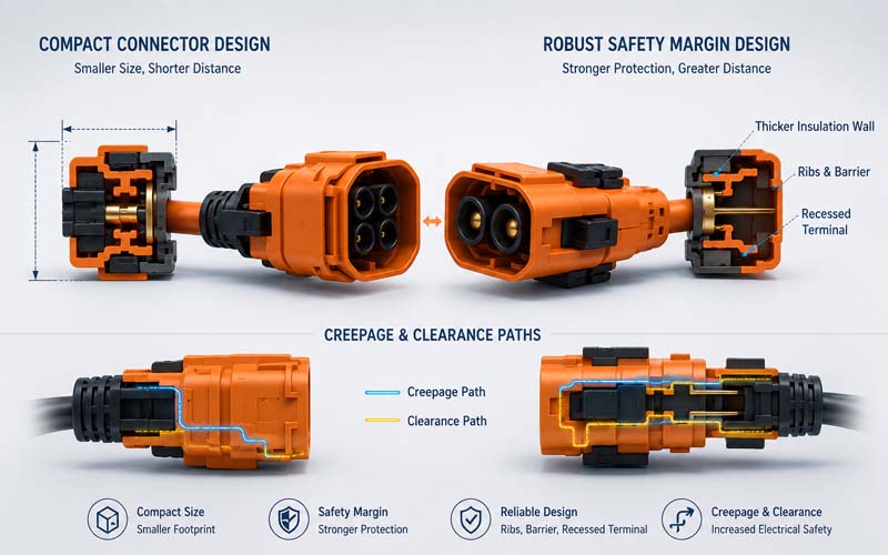
The Creepage and Clearance Challenge

One of the most significant design constraints is maintaining sufficient electrical spacing.

Higher voltages generally require:

  • larger clearance distances
  • longer creepage paths
  • improved insulation structures

However, increasing spacing also increases connector size.

Designers often use:

  • insulating ribs
  • internal barriers
  • recessed terminals
  • optimized conductor geometry

to maximize electrical separation within limited packaging volume.

Compact Design vs Electrical Safety Comparison


Safety Margin vs Minimum Compliance

Meeting a standard requirement is not always enough.

A connector may technically comply with a specified spacing requirement while having limited margin for:

  • manufacturing tolerances
  • contamination
  • aging
  • vibration
  • environmental exposure

Experienced engineers typically design beyond minimum values to improve robustness.


Thermal Performance Trade-Offs

Higher voltage systems often support higher power levels.

To reduce size, designers may attempt to:

  • reduce terminal dimensions
  • decrease connector footprint
  • increase current density

These changes can increase:

  • contact temperature
  • thermal stress
  • material aging

Thermal validation becomes increasingly important in compact 800V designs.


Shielding and EMC Constraints

Modern 800V systems contain:

  • traction inverters
  • onboard chargers
  • DC/DC converters
  • high-speed communication networks

Effective shielding often requires:

  • metal shells
  • conductive backshells
  • 360° shield termination

These features consume valuable packaging space.

Reducing connector size may compromise EMC performance if shielding design is not carefully optimized.


HVIL Integration Challenges

Many 800V connectors incorporate HVIL (High Voltage Interlock Loop) functionality.

Additional HVIL contacts require:

  • dedicated space
  • mechanical protection
  • routing paths
  • insulation separation

Compact packaging increases the complexity of integrating these safety functions.


Mechanical Durability Considerations

Smaller connectors are often more sensitive to:

  • tolerance variation
  • vibration
  • mating misalignment
  • terminal movement

Maintaining long-term durability while reducing size requires careful mechanical design.


Environmental Sealing Trade-Offs

800V connectors frequently require:

  • IP67 protection
  • IP68 protection
  • chemical resistance
  • pressure resistance

Adding robust sealing features increases:

  • connector volume
  • mating force
  • manufacturing complexity

Yet inadequate sealing can significantly reduce safety margins.


Material Selection Becomes More Important

Material choice directly influences:

  • dielectric strength
  • CTI performance
  • thermal stability
  • mechanical durability

Higher-performance materials may allow more compact designs but often increase cost.


Manufacturing Tolerance Considerations

A design that appears acceptable in CAD may become risky in production.

Engineers must account for:

  • molding variation
  • terminal positioning tolerance
  • assembly variation
  • wear over product life

Reduced safety margins leave less room for manufacturing variation.


Validation Requirements for 800V Connectors

Because design margins are tighter, validation becomes more critical.

Typical tests include:

  • HiPot testing
  • insulation resistance testing
  • thermal cycling
  • vibration testing
  • humidity exposure
  • salt spray
  • EMC validation
  • HVIL functional testing

Validation should simulate real operating conditions whenever possible.


Common Design Mistakes

Optimizing Only for Size

Electrical safety margins may become insufficient.

Ignoring Long-Term Aging

Material degradation can reduce insulation performance.

Underestimating EMC Requirements

Shielding limitations often appear late in development.

Relying Solely on Standard Minimums

Minimum compliance does not guarantee robustness.

Reducing Validation Scope

Aggressive packaging requires more testing, not less.


The Best Approach: Balanced Engineering

Successful 800V connector design is not about achieving the smallest possible package.

It is about balancing:

  • electrical safety
  • thermal performance
  • EMC performance
  • manufacturability
  • reliability
  • serviceability

The most reliable connectors typically incorporate appropriate engineering margin rather than pursuing extreme miniaturization.


How FPIC Supports 800V Connector Development

FPIC develops high-voltage connectors and cable assemblies for EV, ESS, and industrial electrification applications.

Our engineering support includes:

  • 800V connector architecture review
  • creepage and clearance optimization
  • HVIL integration
  • shielding design
  • thermal validation
  • prototype development
  • production manufacturing support

We help customers balance compact packaging with long-term reliability and safety.


Final Thoughts

The move to 800V architectures creates significant opportunities for vehicle performance and charging efficiency.

However, higher voltage leaves less room for design mistakes.

Engineers must carefully balance:

  • size
  • weight
  • insulation performance
  • thermal behavior
  • EMC requirements
  • durability

In high-voltage connector design, safety margin is not wasted space—it is often the foundation of long-term reliability.


FAQ

Why are 800V connectors more challenging than 400V connectors?

Higher voltage increases insulation and safety requirements while packaging space continues to shrink.

Can connector size always be reduced?

Not without affecting safety margin, thermal performance, or EMC behavior.

Why are creepage and clearance more critical in 800V systems?

Higher voltage increases the risk of arcing and surface tracking.

Does compact packaging affect EMC?

Yes. Reduced space can limit shielding effectiveness and grounding paths.

Should engineers design beyond minimum standard requirements?

In many applications, additional safety margin improves long-term reliability.


Developing an 800V EV or ESS Platform?

FPIC provides custom high-voltage connectors and cable assemblies designed for 800V architectures, combining compact packaging, robust insulation design, and validated reliability.

Contact us to discuss your high-voltage interconnect requirements.


Resources

  1. ISO 6469 – Electrically Propelled Vehicle Safety Requirements
    Safety requirements for high-voltage EV systems.
  2. IEC 60664-1 – Insulation Coordination for Low-Voltage Systems
    Fundamental guidance on creepage and clearance.
  3. LV214 / LV215 High-Voltage Automotive Connector Standards
    Automotive connector validation and design requirements.
  4. USCAR-2 Automotive Connector Performance Specification
    Connector reliability and environmental test requirements.
  5. TE Connectivity – High Voltage EV Connectivity Solutions
    Industry guidance on EV high-voltage interconnect design.
press-fit terminals

FPIC’s Precision Metal Terminals Redefine Reliability for New Energy Vehicles

In the rapidly evolving world of electric vehicles (EVs) and energy storage systems (ESS), every connection matters. Behind the silent efficiency of a battery pack lies a complex web of conductors, sensors, and signal interfaces — all of which must perform flawlessly under vibration, heat, and extreme environmental conditions.

Traditionally, engineers relied on solder joints to attach sampling wires or signal leads to printed circuit boards (PCBs). However, as vehicles endure long-term vibration and frequent temperature changes, solder points can crack, loosen, or fail — leading to signal interruptions, system alarms, and even vehicle shutdowns.

To eliminate this hidden risk, the industry has embraced a new generation of eyelet terminals (also known as fish-eye terminals) — a zero-solder, press-fit connection technology that has become the benchmark for safety and reliability in modern EV battery systems.


1️⃣ Zero-Solder Technology for Reliable, Long-Term Connections

Eyelet terminals replace traditional soldering with mechanical press-fit technology.
Each terminal is precisely inserted into a plated through-hole on the PCB, forming a gas-tight, cold-welded mechanical bond without heat or solder.

This approach eliminates problems like cold joints, thermal stress, and oxidation, ensuring stable electrical conductivity throughout the battery’s life cycle.
For high-current and high-vibration applications, it offers a proven reliability advantage — meeting the demanding standards of automotive-grade safety.


2️⃣ Optimized Contact Design for Signal Integrity

The terminal’s unique spring-like geometry maintains constant pressure within the hole, minimizing contact resistance and ensuring low temperature rise even under heavy current flow.

By preserving signal integrity in high-load environments, eyelet terminals ensure accurate battery monitoring, voltage sensing, and cell balancing — critical to the safe operation of every EV.


3️⃣ Higher Assembly Efficiency, Lower Manufacturing Risk

Eyelet terminals simplify the manufacturing process by eliminating the need for soldering, flux cleaning, and heat management.
This leads to:
Shorter assembly cycles
Lower defect rates
Improved automation compatibility

For large-scale EV battery production, such as power battery modules and BMS systems, this technology significantly improves throughput, consistency, and process control — perfectly aligning with the industry’s move toward smart manufacturing.


4️⃣ Eco-Friendly Manufacturing for a Sustainable Future

Since no solder or flux is required, press-fit terminal production avoids emissions from solder fumes and reduces waste from cleaning chemicals.
This aligns perfectly with the environmental, social, and governance (ESG) objectives of leading automotive OEMs — supporting green manufacturing and sustainability throughout the supply chain.


5️⃣ Vibration Resistance and Structural Reinforcement

FPIC’s eyelet terminals feature a preformed elastic zone that absorbs vibration and compensates for mechanical stress.
Combined with over-molding technology, this ensures that the terminal remains firmly anchored to the PCB — even under severe vibration and impact.

The result: no loosening, no micro-cracks, and no signal failure, even after tens of thousands of vibration cycles.


6️⃣ Performance in Extreme Environments

Through advanced materials and precision forming, FPIC’s terminals achieve wide temperature tolerance (-40°C to +125°C), excellent corrosion resistance, and stable contact pressure over the product’s full lifecycle.

Whether it’s a fast-charging EV at 125°C, a cold-start at -40°C, or coastal salt-fog exposure, FPIC’s terminals maintain consistent performance and safety.


7️⃣ Full Lifecycle Reliability Testing

Every FPIC eyelet terminal undergoes comprehensive testing in our in-house laboratory, including:

  • Insertion & extraction force validation

  • Thermal cycling and vibration endurance

  • Temperature rise testing

  • Corrosion resistance & salt spray testing

  • Dimensional inspection via KEYENCE systems

This ensures each part meets the highest standards of IATF 16949, ISO 9001, and VDA 19.1 for automotive components — guaranteeing full traceability and reliability across the production chain.


8️⃣ Expanding Applications in EV and Energy Storage Systems

From battery module assemblies and power distribution units (PDUs) to on-board chargers and energy storage containers, eyelet terminals are enabling modular, maintainable, and scalable designs for the new energy era.

Their plug-and-play, serviceable design not only enhances system safety but also streamlines assembly, repair, and recycling — providing an ideal foundation for next-generation solid-state and sodium-ion batteries.


FPIC: Your Reliable Partner for Automotive Metal Components

At Shenzhen Forman Precision Industry Co., Ltd. (FPIC), we specialize in precision metal stamping, CNC machining, and connector component development for the world’s leading automotive and energy companies.

Our machined eyelet terminals combine precision engineering, material innovation, and mass-production capability to ensure the best balance of performance, quality, and cost efficiency.

With decades of expertise and fully certified systems (IATF 16949, ISO 9001, ISO 14001, ISO 13485, and VDA 19.1), FPIC provides customized terminal designs, prototype development, and mass production solutions — all supported by advanced laboratory validation and automated manufacturing lines.

press-fit terminals

Press Fit


Connecting the Future of Electrification

As EVs and energy storage systems become smarter and more powerful, every connection must be stronger, safer, and more reliable than ever before.
FPIC’s eyelet terminal solutions are engineered to make that possible — enabling a safer, cleaner, and more efficient electrified world.

📩 Contact FPIC for customized terminal or connector solutions:
info@fpiconn.com
🌐 www.fpiconn.com