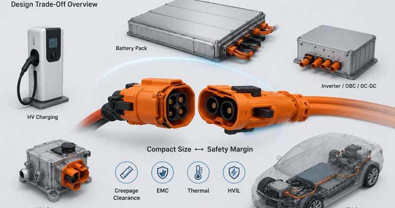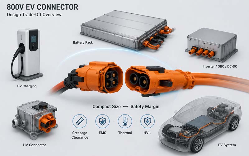
Walk into any electric vehicle battery pack, inverter compartment, or charging system and one feature immediately stands out:
Orange high-voltage connectors.
While many people assume the orange color is simply a visual identifier, these connectors differ from standard power connectors in far more significant ways.
Orange high-voltage (HV) connectors are designed specifically for applications involving hazardous voltages and high-power electrical systems. Their design requirements extend beyond electrical conductivity and include safety, insulation coordination, EMC performance, environmental protection, and validation standards.
This article explains the key differences between orange HV connectors and conventional power connectors used in lower-voltage systems.
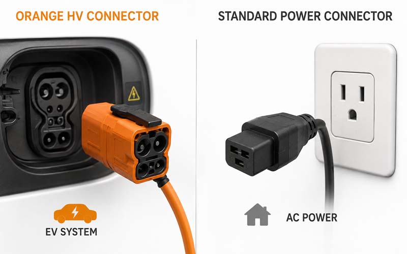
Why Are High-Voltage Connectors Orange?
The orange color serves as an internationally recognized safety indicator.
In EVs and many industrial electrification systems, orange components identify circuits carrying hazardous voltages.
The objective is simple:
- improve technician awareness
- reduce accidental contact risks
- support maintenance procedures
- comply with industry safety practices
However, the color itself does not make the connector safe.
The engineering behind the connector is what matters.
Voltage Levels Are Fundamentally Different
Traditional power connectors often operate at:
- 12V
- 24V
- 48V
EV high-voltage connectors commonly operate at:
- 400V systems
- 800V systems
- 1000V+ ESS systems
Higher voltage introduces additional risks such as:
- electrical arcing
- insulation breakdown
- surface tracking
- transient overvoltage stress
As voltage increases, connector design becomes significantly more complex.
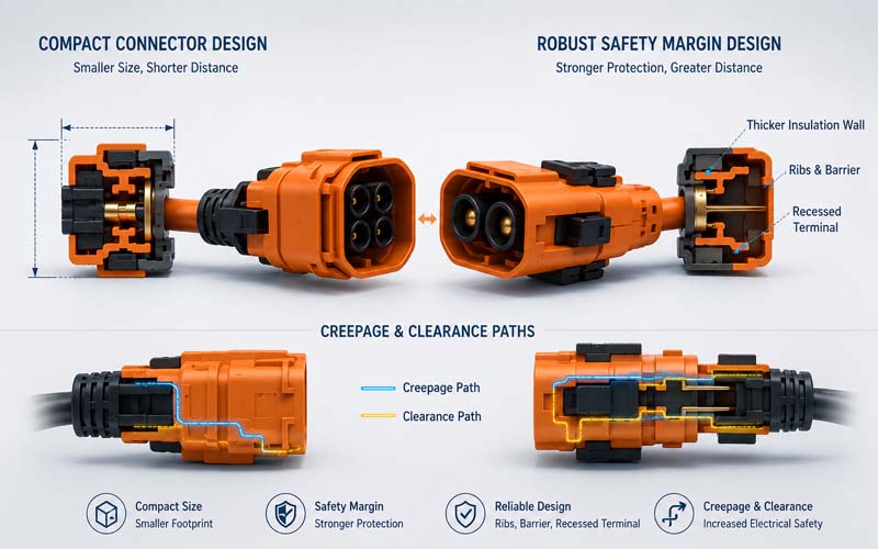
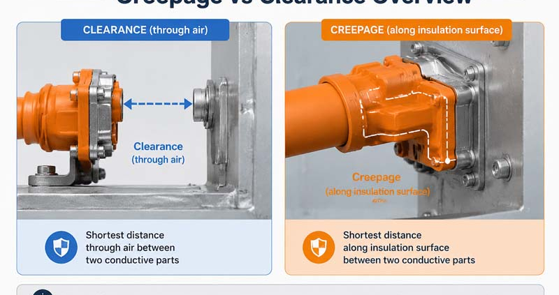
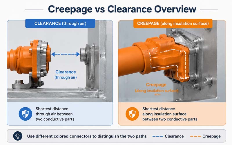
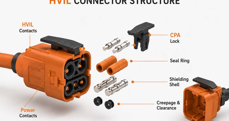
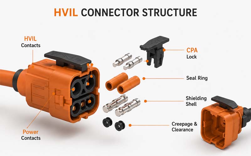
Creepage and Clearance Requirements
One of the biggest differences is insulation coordination.
Orange HV connectors require carefully engineered:
- creepage distances
- clearance distances
- insulation barriers
Standard low-voltage connectors often have minimal spacing requirements because the risk of electrical breakdown is much lower.
In high-voltage systems, insufficient spacing can result in:
- flashover
- carbon tracking
- catastrophic failure
Touch Safety Design
High-voltage connectors must prevent accidental contact with energized conductors.
Common features include:
- finger-safe terminals
- recessed contacts
- touch-proof interfaces
- protective shrouds
Many low-voltage power connectors do not require this level of protection.
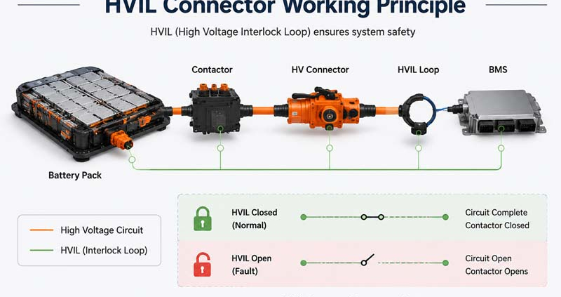
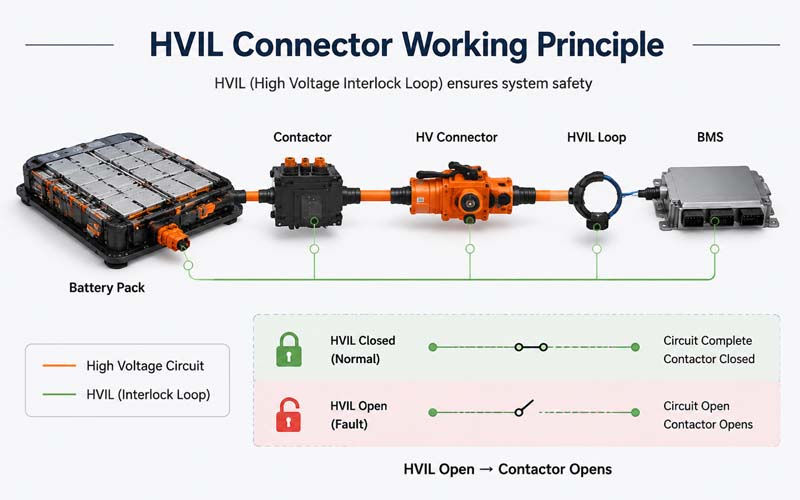
HVIL Integration
Most EV high-voltage connectors incorporate:
HVIL (High Voltage Interlock Loop)
HVIL continuously monitors connector engagement.
If a connector becomes disconnected or partially unmated:
- the HVIL circuit opens
- contactors disconnect high voltage
- the system enters a safe state
Standard power connectors typically do not include this functionality.
Enhanced Locking Mechanisms
Connector separation under load can be dangerous in high-voltage systems.
For this reason, HV connectors often include:
- CPA (Connector Position Assurance)
- secondary locking devices
- mechanical retention features
- visual mating indicators
These systems reduce the risk of incomplete mating and accidental disconnection.
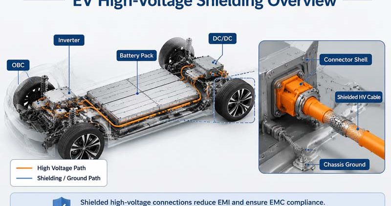
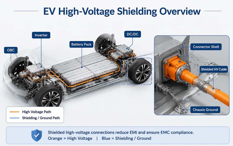
Shielding and EMC Requirements
EV power electronics generate substantial electromagnetic noise.
Orange HV connectors frequently incorporate:
- metal shielding
- conductive backshells
- 360° shield termination
- grounding structures
These features help maintain EMC compliance.
Many standard power connectors are not designed for high-frequency EMC control.
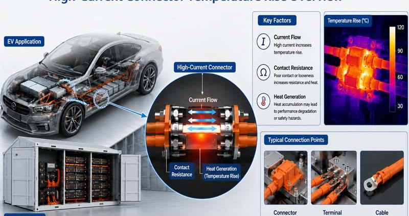
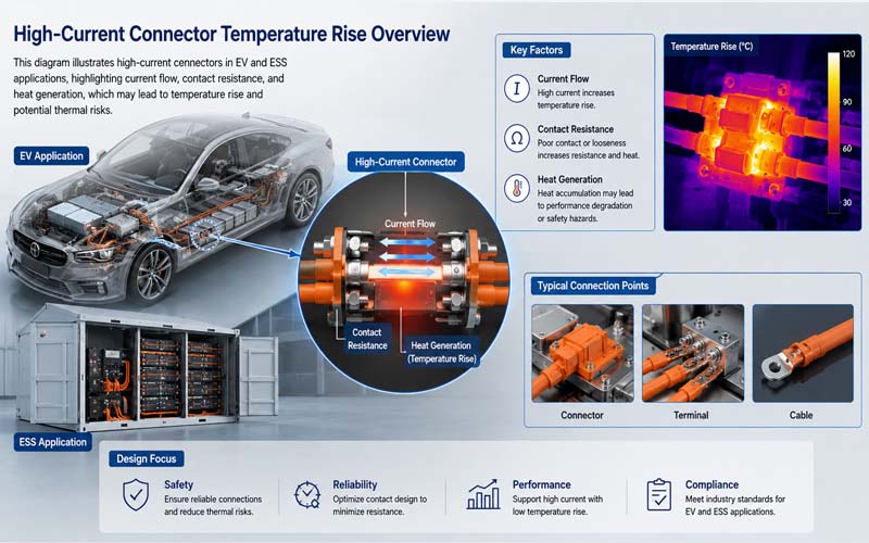
Thermal Performance Expectations
EV connectors often carry:
- high continuous current
- rapid charging current
- inverter power loads
As a result, designers pay close attention to:
- contact resistance
- terminal design
- thermal rise
- current cycling performance
Thermal validation is generally more demanding than for conventional power connectors.
Environmental Protection Requirements
High-voltage connectors frequently operate in:
- battery packs
- underbody locations
- motor compartments
- charging systems
Common requirements include:
- IP67 sealing
- IP68 sealing
- vibration resistance
- chemical resistance
- thermal cycling durability
Environmental exposure can directly affect electrical safety.
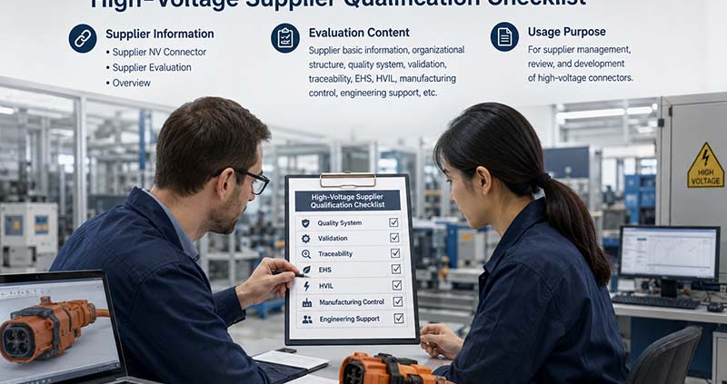
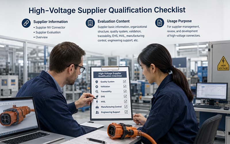
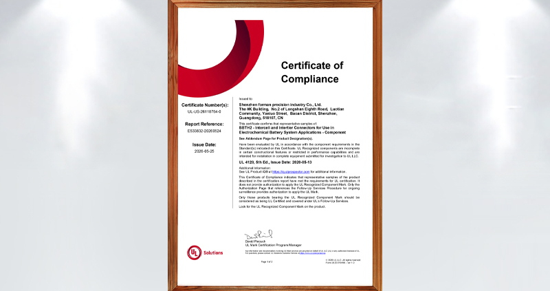
Validation Standards Are More Demanding
Orange HV connectors must typically satisfy extensive validation programs.
Common tests include:
- dielectric withstand (HiPot)
- insulation resistance
- vibration testing
- thermal shock
- salt spray
- humidity exposure
- HVIL validation
- EMC testing
These requirements exceed those of many standard power connector applications.
Serviceability Considerations
High-voltage systems require controlled service procedures.
Connectors often include:
- service disconnect functions
- maintenance lockouts
- visual safety indicators
- tool-assisted release mechanisms
Safety during maintenance is a major design priority.
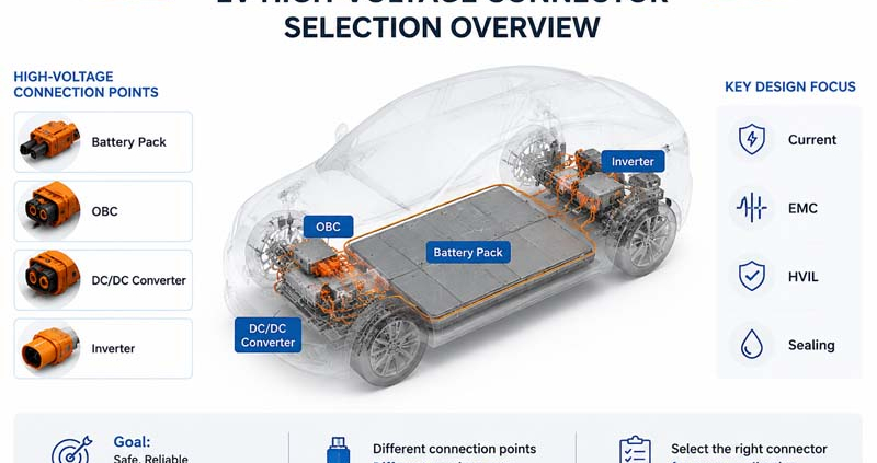
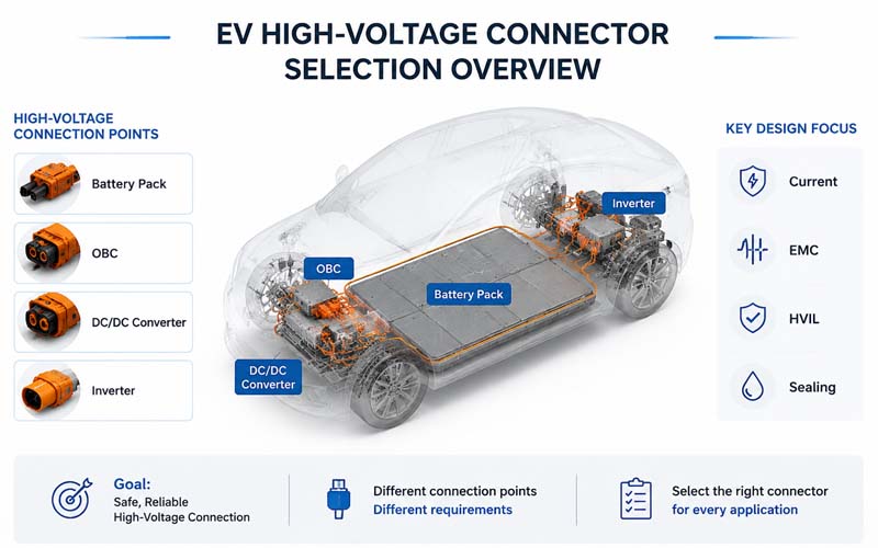
Typical Applications for Orange HV Connectors
Common applications include:
EV Battery Packs
High-current battery interfaces.
Inverters
Motor drive power connections.
Onboard Chargers (OBC)
AC-to-DC charging systems.
DC/DC Converters
High-voltage to low-voltage power conversion.
Energy Storage Systems (ESS)
Battery energy storage power distribution.
Fast Charging Equipment
High-power charging infrastructure.
Common Misconceptions
Orange Color Alone Means Safe
False.
The color is only a visual identifier.
Safety comes from:
- insulation design
- HVIL
- locking systems
- validation testing
Any Power Connector Can Be Used in HV Applications
False.
High-voltage systems require specialized designs and validation.
Current Rating Is the Only Important Specification
False.
Voltage, insulation, EMC, and environmental performance are equally important.
How FPIC Supports High-Voltage Connectivity
FPIC develops custom high-voltage connectors and cable assemblies for:
- EV platforms
- ESS systems
- industrial electrification
- charging infrastructure
Our capabilities include:
- HVIL integration
- shielding design
- creepage and clearance optimization
- thermal validation
- environmental testing support
- custom cable assembly manufacturing
We help customers develop safe and reliable high-voltage interconnect solutions.
Final Thoughts
Orange high-voltage connectors represent far more than a color standard.
Compared with conventional power connectors, they incorporate:
- enhanced insulation systems
- touch-safe interfaces
- HVIL functionality
- shielding structures
- advanced locking mechanisms
- rigorous validation requirements
As EV and energy storage systems continue moving toward higher voltages and power densities, connector design plays an increasingly critical role in system safety and reliability.
FAQ
Why are EV high-voltage connectors orange?
Orange provides a visual warning that hazardous voltage may be present.
What is the biggest difference between HV and standard power connectors?
Electrical safety requirements, including insulation, HVIL, and touch protection.
Do all orange connectors contain HVIL?
Not all, but HVIL is widely used in automotive high-voltage systems.
Why do HV connectors require shielding?
To control EMC issues generated by high-power electronics.
Can standard power connectors be used in EV battery systems?
Generally no. Specialized high-voltage connectors are required.
Looking for High-Voltage Connector Solutions?
FPIC provides custom high-voltage connectors and cable assemblies with HVIL, shielding, sealing, and validation support for EV, ESS, and industrial applications.
Contact us to discuss your high-voltage connectivity requirements.
Resources
- ISO 6469 – Electrically Propelled Vehicle Safety Requirements
International safety requirements for EV high-voltage systems. - LV215 – High Voltage Connector Systems for Road Vehicles
Automotive requirements for HV connector systems. - USCAR-2 – Automotive Connector Performance Specification
Environmental and electrical validation requirements. - IEC 60664-1 – Insulation Coordination Standard
Creepage and clearance design requirements. - TE Connectivity – High Voltage EV Connectivity Solutions
Technical guidance on EV high-voltage connector systems.