Temperature Rise Testing for High-Current Connectors: Key Risks and Test Setup
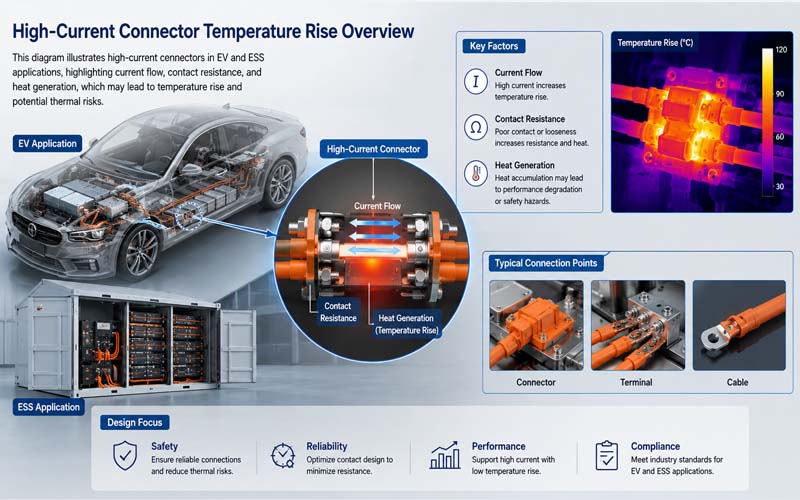
As electric vehicles (EVs), energy storage systems (ESS), and industrial electrification platforms continue increasing in power density, high-current connectors thermal performance has become a major engineering concern.
High-current connectors must safely carry large amounts of current for extended periods without excessive heating.
Even small increases in contact resistance can generate significant heat under high current conditions.
Temperature rise testing is therefore one of the most important validation methods for high-current connectors and cable assemblies.
This article explains why temperature rise testing matters, how test setups are designed, and the key failure risks engineers should monitor.
Why Temperature Rise Testing Is Critical
A connector may pass continuity and dielectric tests while still suffering from poor thermal performance.
Excessive temperature rise can lead to:
- insulation degradation
- contact oxidation
- reduced spring force
- thermal runaway
- voltage drop
- accelerated aging
- connector melting
Thermal issues are especially important in:
- EV battery systems
- inverters
- OBC interfaces
- DC fast charging
- ESS battery cabinets
Basic Principle of Temperature Rise Testing
The test measures how much the connector temperature increases above ambient while carrying current.
The general process includes:
1.Apply specified current
2.Stabilize thermal conditions
3.Measure conductor and terminal temperatures
4.Compare temperature rise against acceptance criteria
The test evaluates the combined effect of:
- contact resistance
- conductor size
- terminal design
- plating quality
- cooling conditions
What Causes Temperature Rise?
Heat generation mainly comes from electrical resistance.
The power loss relationship is approximately:
P = I²R
This means:
- doubling current increases heat dramatically
- small resistance increases can create large thermal effects
Critical resistance sources include:
- contact interface resistance
- crimp resistance
- conductor resistance
- degraded plating surfaces
Typical Test Setup
A temperature rise test setup generally includes:
- programmable current source
- calibrated thermocouples
- data acquisition system
- test fixture
- controlled ambient environment
The connector is assembled using production-intent components and cable lengths.
Thermocouple Placement
Common measurement points include:
- contact interface area
- terminal crimp area
- cable conductor near the connector
- housing surface
Proper sensor attachment is critical for accurate results.
Steady-State Testing
Most tests continue until thermal stabilization occurs.
Steady state is typically defined as:
temperature change below a specified threshold over time
Depending on current level and connector mass, stabilization may require several hours.
Continuous Current vs Peak Current
Validation often includes both:
Continuous Current Testing
Evaluates long-term thermal capability.
Peak or Overload Testing
Assesses short-duration thermal stress.
Real applications may experience both conditions.
Important Environmental Factors
Temperature rise depends heavily on installation conditions.
Factors include:
- ambient temperature
- airflow
- cable bundling
- enclosure confinement
- mounting orientation
Catalog ratings may not represent actual system conditions.
Common Failure Risks
High Contact Resistance
Poor contact interfaces create localized heating.
Inadequate Crimp Quality
Poor crimps increase resistance and heat generation.
Reduced Contact Force
Thermal cycling may weaken terminal spring force.
Poor Shield Grounding
In shielded connectors, grounding paths may also heat.
Insufficient Cooling
Compact packaging can trap heat.
Thermal Aging Effects
Long-term exposure to elevated temperature may cause:
- oxidation
- plastic deformation
- plating degradation
- insulation hardening
- creep relaxation
Temperature rise testing is often combined with aging cycles.
Acceptance Criteria
Acceptance limits depend on:
- connector material
- insulation class
- application standard
- OEM requirements
Many standards specify maximum allowable temperature rise above ambient.
Relevant Standards
Common references include:
- USCAR-2
- LV214
- IEC 60512
- UL connector standards
- OEM-specific validation requirements
Correlation with Other Tests
Temperature rise testing should be combined with:
- contact resistance testing
- thermal cycling
- vibration testing
- humidity exposure
- mechanical durability testing
Many connector failures occur only after combined stress exposure.
Typical Applications
Temperature rise testing is essential for:
- battery pack connectors
- charging connectors
- inverter interfaces
- busbar connections
- ESS power connectors
- industrial high-current systems
How FPIC Supports Thermal Validation
FPIC provides high-current connector and cable assembly solutions with:
- thermal performance evaluation
- crimp resistance control
- contact resistance verification
- current cycling validation
- customized test support
- EV and ESS application engineering
We help customers optimize connector reliability under real operating conditions.
Final Thoughts
Temperature rise testing is one of the most important validation methods for high-current connectors.
A successful design depends on:
- low and stable resistance
- robust contact systems
- controlled crimp quality
- realistic installation conditions
- comprehensive validation
As power density increases in EV and energy systems, thermal validation becomes increasingly critical to long-term reliability and safety.
FAQ
Why is temperature rise testing important?
It verifies whether a connector can safely carry current without overheating.
What mainly causes connector heating?
Electrical resistance at contacts, crimps, and conductors.
Does ambient temperature affect results?
Yes. Installation environment strongly influences thermal performance.
Can a connector pass electrical tests but fail thermally?
Yes. Low-level electrical tests may not reveal thermal weaknesses.
Why is steady-state testing necessary?
Because some thermal failures appear only after long stabilization periods.
Need Reliable High-Current Connector Solutions?
FPIC supports EV, ESS, and industrial projects with custom high-current connectors and cable assemblies validated for thermal performance and long-term reliability.
Contact us to discuss your application requirements.
Resources
- USCAR-2 – Automotive Connector Performance Specification
Defines connector environmental and thermal validation requirements. - IEC 60512 – Connector Test Methods
International connector electrical and mechanical test procedures. - LV214 Automotive Connector Validation Standard
Automotive connector qualification requirements. - TE Connectivity – High Current Connector Thermal Design
Thermal considerations for high-power connectors. - Molex – Power Connector Thermal Performance Guide
Connector current carrying and temperature rise guidance.