High-Voltage Connector Shielding Design: How to Manage EMC in EV Systems
Electric vehicles contain some of the most electrically demanding environments in modern engineering.
Inverters, DC/DC converters, onboard chargers, and fast-switching traction systems generate significant electromagnetic noise. Without effective shielding, this noise can interfere with communication networks, sensors, and vehicle electronics.
While shielded cable is an essential first step, overall EMC performance depends heavily on how the shield is terminated through the connector system.
This article explains how high-voltage connector shielding works, common design pitfalls, and the validation methods used to verify EMC performance.
Why Shielding Matters in EV High-Voltage Systems
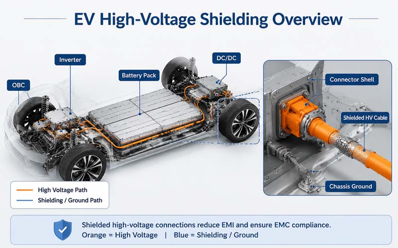
Typical EV high-voltage cables connect:
- battery pack
- inverter
- onboard charger
- DC/DC converter
- electric compressor
- PDU
These circuits carry high current with rapid switching edges, producing both conducted and radiated emissions.
Potential consequences of poor shielding include:
- CAN and Ethernet communication errors
- sensor disturbances
- failed EMC compliance tests
- unintended controller resets
Connector shielding helps maintain continuous low-impedance paths for high-frequency currents.
Basic Shielding Principle
Cable shields work by directing high-frequency noise currents to chassis ground.
For shielding to be effective, the current path must remain continuous across:
- cable shield
- backshell
- connector shell
- equipment enclosure
Any discontinuity increases impedance and reduces attenuation.
360° Shield Termination
The most effective approach is a full circumferential, or 360°, shield termination.
This method:
- maximizes shield coverage
- minimizes transfer impedance
- avoids long pigtails
- improves high-frequency performance
Pigtail terminations are generally less effective at high frequencies.
Connector Design Elements for Shielding
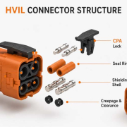
High-voltage shielded connectors may include:
- metal shells
- conductive backshells
- spring fingers
- shield clamps
- conductive gaskets
These components maintain electrical continuity between cable shield and vehicle chassis.
Grounding Strategy
Shield termination usually connects to chassis ground.
Key considerations include:
- low contact resistance
- corrosion protection
- stable mechanical retention
- compatibility with system grounding architecture
The objective is low impedance across the relevant frequency range.
Transfer Impedance and Shield Effectiveness
Shield performance is often characterized by transfer impedance.
Lower transfer impedance generally indicates better shielding effectiveness.
Connector design, material choice, and termination quality all influence this parameter.
Common Design Mistakes
Long Shield Pigtails
Increase inductance and degrade high-frequency shielding.
Incomplete Circumferential Contact
Creates local impedance discontinuities.
Poor Corrosion Resistance
Raises contact resistance over time.
Weak Mechanical Retention
Allows micro-motion and fretting.
Discontinuous Shield Path
Reduces attenuation effectiveness.
Mechanical and Environmental Requirements
Shield terminations must remain effective under:
- vibration
- thermal cycling
- humidity
- salt spray
- mechanical shock
EMC performance must be maintained throughout the product life.
Validation Methods
Typical validation tests include:
- shield continuity resistance
- transfer impedance measurement
- radiated emissions
- conducted emissions
- bulk current injection (BCI)
- vibration and thermal aging followed by EMC retest
Testing before and after environmental exposure is essential.
Relationship Between Shielding and HV Safety
Shield design must coexist with high-voltage requirements such as:
- creepage and clearance
- insulation resistance
- HiPot withstand
- touch safety
EMC and safety requirements must be balanced within the same connector package.
Typical Applications
Shielded high-voltage connectors are used in:
- battery-to-inverter cables
- onboard charger connections
- DC fast charging interfaces
- electric compressors
- ESS power systems
How FPIC Supports Shielded HV Connector Design
FPIC provides custom high-voltage connector and cable assembly solutions featuring:
- 360° shield termination
- integrated backshells
- HVIL support
- sealing and mechanical locking
- continuity, IR, HiPot, and EMC-related validation
Our engineering team helps customers optimize both electrical safety and EMC performance.
Final Thoughts
In EV systems, shielding performance depends on the entire connector and cable assembly—not just the cable itself.
A reliable design requires:
- continuous shield paths
- low-impedance termination
- corrosion-resistant grounding
- mechanical robustness
- environmental validation
Effective connector shielding is a key contributor to EMC compliance and system reliability.
FAQ
Why is 360° shield termination preferred?
It minimizes inductance and provides superior high-frequency performance.
What is transfer impedance?
A measure of how effectively a shield limits noise transfer.
Can a cable shield work with a poor connector termination?
No. Connector termination is often the determining factor in overall shielding effectiveness.
Does corrosion affect EMC?
Yes. Increased contact resistance raises shield impedance.
Should EMC performance be tested after vibration?
Yes. Mechanical stress can degrade shield continuity.
Need High-Voltage Connectors with Robust Shielding Performance?
FPIC designs custom shielded high-voltage connectors and cable assemblies for EV and energy storage systems.
Contact us to discuss your EMC and high-voltage interconnect requirements.
Resources
- CISPR 25 – Vehicle EMC Requirements
Standard for radiated and conducted emissions in vehicles. - ISO 11452 – Road Vehicle EMC Immunity Testing
EMC immunity test methods including BCI. - LV214 – Automotive Connector Validation Standard
Environmental and electrical requirements for automotive connectors. - TE Connectivity – Shield Termination Design Guide
Practical guidance on 360° shield grounding. - Molex – High-Voltage Shielded Connector Solutions
Connector design approaches for EV EMC performance.