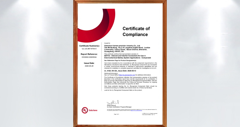
450A energy storage connector UL certificate

FPIC is pleased to announce that representative samples of our 2000V 450A energy storage connector series have been evaluated by UL for use in electrochemical battery system applications. The certification documents identify the product under UL 4128, 5th Edition, covering intercell and intertier connectors for battery system use.

This milestone strengthens FPIC’s capability in high-current battery interconnection solutions and provides additional confidence for customers developing energy storage equipment, battery packs, and related power distribution systems.

What This Certification Covers

According to the UL Certificate of Compliance, the evaluated product category is BBTH2 – Intercell and Intertier Connectors for Use in Electrochemical Battery System Applications – Component, with certificate number UL-US-26118764-0 and report reference E533832-20260524. The issue date is 2026-05-25.

The corresponding UL report describes the product as:

  • Cable Connectors
    Cat. Nos. A083-1F14-C150N-6A-##, A083-1F14-C150N-5A-##, A083-1F14-C150N-0A-##
  • Panel Mounted Inlets
    Cat. Nos. A083-2M14-E014F-6A-##, A083-2M14-E014F-5A-##, A083-2M14-E014F-0A-##

The report also states the key ratings of this series as 2000V DC and 450A. For the cable connector version, the evaluated conductor size is 300 kcmil.

FPIC 450A Energy Connector Meets UL 4128

Why This Matters for Energy Storage Applications

High-current battery connection points in energy storage systems demand more than basic electrical performance. They also require controlled insulation design, reliable mating, proper polarity identification, and suitability for integration into complete battery equipment.

The UL report identifies these products as intercell/intertier connectors intended for use in electrochemical battery equipment, including cable connector and panel mounted inlet configurations. The panel mounted inlet versions are intended for factory assembly onto copper conductors rated 90°C or higher and/or copper or copper alloy busbars in battery equipment.

For ESS manufacturers, battery pack integrators, and related equipment developers, this provides an important compliance reference point when evaluating connector solutions for high-voltage, high-current battery system designs.

Key Product Characteristics

Based on the UL report, FPIC’s 450A connector series includes the following core characteristics:

1. High Voltage and High Current Capability

The evaluated series is rated at 2000V DC and 450A, supporting demanding battery interconnection applications.

2. Cable and Panel-Mounted Configurations

The series includes both cable connector and panel mounted inlet versions, helping customers build matching connection interfaces for different battery system architectures.

3. Single-Pole Intercell / Intertier Connector Design

The report describes the cable connector products as insulated, single-pole mating intercell/intertier connectors, suitable for battery system connection needs.

4. Support for Battery Equipment Integration

The panel mounted inlet versions are intended for assembly to busbars or conductors in electrochemical battery equipment, which is especially relevant for energy storage cabinets, battery packs, and related systems.

Important Compliance Note

The UL certificate clearly states that these are UL Recognized components, not complete end-use equipment. It also states that the certificate itself does not provide authorization to apply the UL Recognized Component Mark; only products bearing the appropriate UL Recognized Component Mark and covered under UL follow-up services should be considered UL Certified within that program context.

In addition, the UL report notes that these devices are:

  • not suitable for disconnecting under load
  • not intended for use outside an equipment enclosure
  • not investigated for an environment rating
  • intended for use only in complete equipment where acceptability is determined in the end-use application

This is important for customers who are designing certified end products and need to evaluate the connector as part of the complete system.

What This Means for FPIC Customers

This UL milestone demonstrates FPIC’s continued progress in energy storage connector development and supports our ability to serve customers with more robust interconnection solutions for battery system applications.

For customers working on:

  • energy storage systems
  • electrochemical battery equipment
  • battery pack integration
  • power distribution interfaces
  • high-current cabinet connections

this development provides stronger confidence in FPIC’s capability to support demanding connector projects with both product development and manufacturing execution.

FPIC Energy Storage Connector Capability

FPIC has been continuously developing energy storage connector solutions for high-current and high-voltage applications. Our energy storage product direction includes connector and cable solutions designed for battery modules, battery packs, and related ESS equipment. FPIC’s internal product materials also describe energy storage connectors with features such as touch-proof design, multiple connection methods, and compliance direction aligned with UL 4128.

This new 450A certification-related progress further strengthens FPIC’s position in the energy storage connector segment.

Contact FPIC for Energy Storage Connector Projects

If you are developing battery packs, ESS cabinets, or related electrochemical battery equipment and need a reliable high-current connector solution, FPIC can support your project with product information, engineering communication, and manufacturing support.

Contact us to discuss your application requirements.

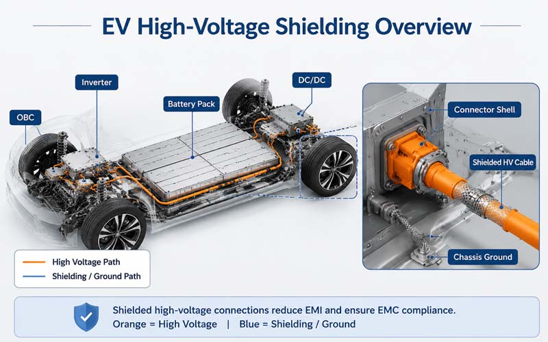
EV High-Voltage Shielding Overview

Electric vehicles contain some of the most electrically demanding environments in modern engineering.

Inverters, DC/DC converters, onboard chargers, and fast-switching traction systems generate significant electromagnetic noise. Without effective shielding, this noise can interfere with communication networks, sensors, and vehicle electronics.

While shielded cable is an essential first step, overall EMC performance depends heavily on how the shield is terminated through the connector system.

This article explains how high-voltage connector shielding works, common design pitfalls, and the validation methods used to verify EMC performance.


Why Shielding Matters in EV High-Voltage Systems

Typical EV high-voltage cables connect:

  • battery pack
  • inverter
  • onboard charger
  • DC/DC converter
  • electric compressor
  • PDU

These circuits carry high current with rapid switching edges, producing both conducted and radiated emissions.

Potential consequences of poor shielding include:

  • CAN and Ethernet communication errors
  • sensor disturbances
  • failed EMC compliance tests
  • unintended controller resets

Connector shielding helps maintain continuous low-impedance paths for high-frequency currents.

EV High-Voltage Shielding Overview


Basic Shielding Principle

Cable shields work by directing high-frequency noise currents to chassis ground.

For shielding to be effective, the current path must remain continuous across:

  • cable shield
  • backshell
  • connector shell
  • equipment enclosure

Any discontinuity increases impedance and reduces attenuation.


360° Shield Termination

The most effective approach is a full circumferential, or 360°, shield termination.

This method:

  • maximizes shield coverage
  • minimizes transfer impedance
  • avoids long pigtails
  • improves high-frequency performance

Pigtail terminations are generally less effective at high frequencies.


Connector Design Elements for Shielding

High-voltage shielded connectors may include:

  • metal shells
  • conductive backshells
  • spring fingers
  • shield clamps
  • conductive gaskets

These components maintain electrical continuity between cable shield and vehicle chassis.


Grounding Strategy

Shield termination usually connects to chassis ground.

Key considerations include:

  • low contact resistance
  • corrosion protection
  • stable mechanical retention
  • compatibility with system grounding architecture

The objective is low impedance across the relevant frequency range.


Transfer Impedance and Shield Effectiveness

Shield performance is often characterized by transfer impedance.

Lower transfer impedance generally indicates better shielding effectiveness.

Connector design, material choice, and termination quality all influence this parameter.


Common Design Mistakes

Long Shield Pigtails

Increase inductance and degrade high-frequency shielding.

Incomplete Circumferential Contact

Creates local impedance discontinuities.

Poor Corrosion Resistance

Raises contact resistance over time.

Weak Mechanical Retention

Allows micro-motion and fretting.

Discontinuous Shield Path

Reduces attenuation effectiveness.


Mechanical and Environmental Requirements

Shield terminations must remain effective under:

  • vibration
  • thermal cycling
  • humidity
  • salt spray
  • mechanical shock

EMC performance must be maintained throughout the product life.


Validation Methods

Typical validation tests include:

  • shield continuity resistance
  • transfer impedance measurement
  • radiated emissions
  • conducted emissions
  • bulk current injection (BCI)
  • vibration and thermal aging followed by EMC retest

Testing before and after environmental exposure is essential.


Relationship Between Shielding and HV Safety

Shield design must coexist with high-voltage requirements such as:

  • creepage and clearance
  • insulation resistance
  • HiPot withstand
  • touch safety

EMC and safety requirements must be balanced within the same connector package.


Typical Applications

Shielded high-voltage connectors are used in:

  • battery-to-inverter cables
  • onboard charger connections
  • DC fast charging interfaces
  • electric compressors
  • ESS power systems

How FPIC Supports Shielded HV Connector Design

FPIC provides custom high-voltage connector and cable assembly solutions featuring:

  • 360° shield termination
  • integrated backshells
  • HVIL support
  • sealing and mechanical locking
  • continuity, IR, HiPot, and EMC-related validation

Our engineering team helps customers optimize both electrical safety and EMC performance.


Final Thoughts

In EV systems, shielding performance depends on the entire connector and cable assembly—not just the cable itself.

A reliable design requires:

  • continuous shield paths
  • low-impedance termination
  • corrosion-resistant grounding
  • mechanical robustness
  • environmental validation

Effective connector shielding is a key contributor to EMC compliance and system reliability.


FAQ

Why is 360° shield termination preferred?

It minimizes inductance and provides superior high-frequency performance.

What is transfer impedance?

A measure of how effectively a shield limits noise transfer.

Can a cable shield work with a poor connector termination?

No. Connector termination is often the determining factor in overall shielding effectiveness.

Does corrosion affect EMC?

Yes. Increased contact resistance raises shield impedance.

Should EMC performance be tested after vibration?

Yes. Mechanical stress can degrade shield continuity.


Need High-Voltage Connectors with Robust Shielding Performance?

FPIC designs custom shielded high-voltage connectors and cable assemblies for EV and energy storage systems.

Contact us to discuss your EMC and high-voltage interconnect requirements.


Resources

  1. CISPR 25 – Vehicle EMC Requirements
    Standard for radiated and conducted emissions in vehicles.
  2. ISO 11452 – Road Vehicle EMC Immunity Testing
    EMC immunity test methods including BCI.
  3. LV214 – Automotive Connector Validation Standard
    Environmental and electrical requirements for automotive connectors.
  4. TE Connectivity – Shield Termination Design Guide
    Practical guidance on 360° shield grounding.
  5. Molex – High-Voltage Shielded Connector Solutions
    Connector design approaches for EV EMC performance.
Square Pin Terminals vs. Automotive Rounded Pin Terminals

A square pin terminal works well in standard PCB headers and low-vibration electronics. An automotive rounded pin terminal is built for stronger guidance, better vibration resistance, improved self-cleaning contact, and higher long-term reliability. If the application is automotive or high-reliability industrial equipment, the rounded automotive design is usually the better choice.

The main difference is not just the shape. Standard square pin terminals prioritize easy insertion and low cost for general electronics, while automotive rounded pin terminals are designed for vibration resistance, guided mating, stable contact, and long service life in harsher environments. Their structure, stamping process, plating method, and performance targets are all different.

If you only look at the pin tip, the difference may seem small. In real applications, though, terminal geometry affects contact stability, corrosion resistance, plating consistency, insertion feel, and even failure risk over time. This article breaks down the differences step by step so engineers, sourcing teams, and product managers can make better design decisions.

Start With the Right Terminology

Before comparing the products, it is important to use the right language.

In this article:

  • Standard square pin terminal means the square or flat-edged metal pin commonly used in PCB pin headers.
  • Automotive rounded pin terminal means the rounded or bullet-shaped male terminal used in automotive low-voltage connector systems.

This distinction matters because industry-leading suppliers do not treat pin headers and terminals as the same category. Aptiv’s public connection systems catalog lists Connectors, Terminals, Seals, and Pin Headers as separate product groups, which confirms that “pin header” and “automotive terminal” should not be used interchangeably.

Why This Comparison Matters

Automotive connectors work in a very different environment from ordinary board-level connectors.

According to VDA, electrical and electronic components in vehicles must continuously adapt to stricter requirements around safety, reliability, environmental exposure, vibration, temperature, and chemical resistance. VDA also highlights that wiring systems and connector components are part of that evolving standardization work.

That is why a terminal for a vehicle cannot be chosen the same way as a terminal for a simple PCB header. Even if both parts are conductive metal pins, the design priorities are different:

  1. Consumer electronics focus more on cost, compactness, and ease of assembly
  2. Automotive systems focus more on durability, vibration stability, and long-term consistency
  3. Harsh environments require stronger protection against debris, contact instability, plating wear, and corrosion

FPIC’s internal technical comparison document makes the same point very clearly: a standard square pin terminal is meant for lower-stress electronic connections, while the automotive rounded pin terminal is designed for high-vibration, high-reliability service conditions.

Structural Differences

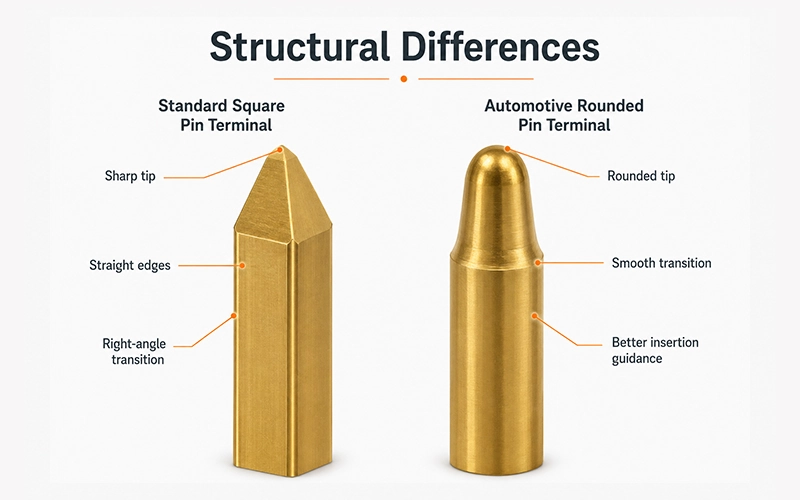
Square Pin Terminals vs. Automotive Rounded Pin Terminals

Standard Square Pin Terminals

A standard square pin terminal usually has:

  • Tip: Sharp/pyramidal, small flat surface, obvious edges
  • Root: 90° dead-angle
  • Design focus: Easy insertion, low cost, for consumer electronics (low vibration, few insertions)
  • Example applications: PCB headers, low-end electronic devices, DuPont-style wiring

This kind of structure is common in:

  • Board-to-board connections
  • Standard PCB headers
  • Consumer electronics
  • Simple control boards
  • Low-vibration devices

The main benefits are easy insertion, easy manufacturing, and lower cost. But the structure also has limitations. Sharp edges and dead corners can create areas where stress concentrates, and in demanding environments they are less forgiving.

Automotive Rounded Pin Terminals

An automotive rounded pin terminal usually has:

  • Tip: Rounded bullet-head / dome-shaped
  • Root: Smooth tapered transition, no dead corner
  • Pin body: Thicker, stronger
  • Core benefits: Guided insertion, vibration resistance, self-cleaning, short-circuit protection
  • Designed for automotive harsh conditions: ECU, BCM, lighting, window, seat control modules

This design offers several practical advantages:

  • Better insertion guidance
  • Reduced scraping at the mating interface
  • More stable contact behavior
  • Better vibration resistance
  • Lower risk of debris staying in sharp dead corners
  • Improved contact reliability over long service life

Structural Comparison Table

ItemStandard Square Pin TerminalAutomotive Rounded Pin Terminal
Tip shapeSharp / pyramidal / flat-edgedRounded / bullet-shaped / dome-like
Root transition90° style transition, dead-corner tendencySmooth tapered transition
Edge conditionObvious corners and flat facesRounded surface, fewer stress points
Contact styleFlat or edge-dominantArc-guided, more stable engagement
Main design goalEasy insertion, simple structure, lower costGuidance, vibration resistance, reliability
Typical environmentGeneral electronicsAutomotive low-voltage systems
Debris toleranceLowerBetter
Reliability expectationBasicHigh

Why Rounded Geometry Helps in Automotive Use

The rounded automotive design is not just about appearance. It changes how the terminal behaves during mating and in long-term service.

1. Better Guidance

A rounded tip helps the male terminal find its way into the mating contact more smoothly. This matters when connector tolerances, insertion angle variation, or assembly speed introduce small alignment changes.

2. Better Vibration Resistance

In vehicles, connectors see repeated vibration from engine systems, road conditions, opening and closing actions, and general operating movement. A more robust and better-guided terminal geometry helps maintain a stable contact relationship.

3. Better Self-Cleaning Behavior

When two contacts mate and unmate repeatedly, a rounded guided structure can help wipe the contact area more consistently. FPIC’s internal document specifically notes this self-cleaning advantage as one reason automotive rounded terminals better resist contamination-related issues.

4. Lower Short-Circuit Risk

The internal comparison also notes that the absence of obvious dead-angle geometry helps reduce the chance of debris buildup around the terminal root, which is one of the practical design benefits of the automotive rounded form.

Industry Background and Design Thinking

FPIC’s internal document cites historical automotive field-failure discussions as a turning point in how the industry views low-voltage terminal design. The document explains that older low-voltage connector approaches using more ordinary square-pin-like forms could create higher risk when vibration, thermal cycling, and debris were involved, which pushed the market toward more robust automotive-specific terminal geometry.

Even without repeating every historical claim, the design lesson is clear:

Automotive connectors are not just “stronger consumer connectors.” They are engineered differently because the environment is different.

That view also aligns with the broader work of VDA and USCAR, where connector systems and related specifications are continuously reviewed to meet the demands of safety, durability, and vehicle operating conditions.

Manufacturing Process Differences

The structure difference is only one part of the story. The manufacturing route is also very different.

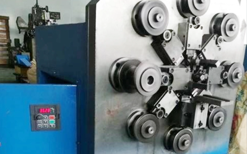
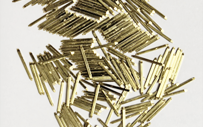
How Standard Square Pin Terminals Are Made

  • Equipment: Multi-wheel forming machines
  • Process: Wire extrusion → straightening → forming → cutting
  • Output: Loose independent pins
  • Automation: Limited
  • Use case: Standard PCB headers

How Standard Square Pin Terminals Are Made

How Standard Square Pin Terminals Are Made

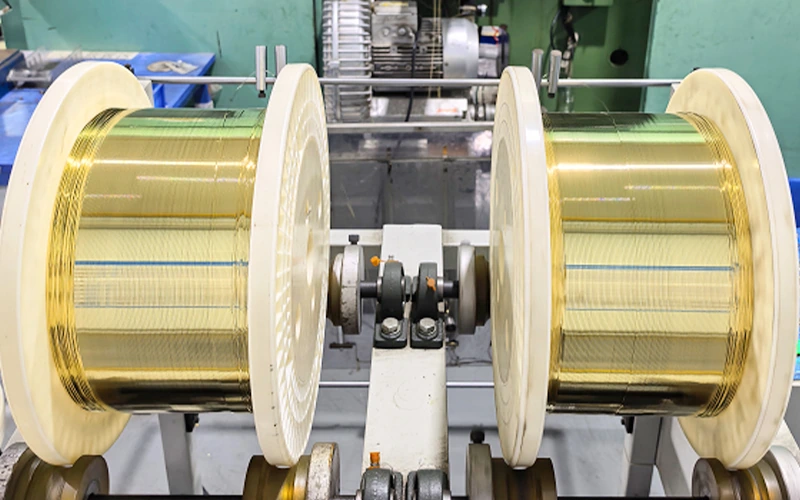
How Automotive Rounded Pin Terminals Are Made

  • Equipment: High-speed precision stamping, continuous progressive dies
  • Process: Brass strip → stamping → punching → bending → forming → cutting
  • Output: Continuous strip carrier for automated assembly
  • Automation: High compatibility, precise dimensions, supports reel-to-reel plating

How Automotive Rounded Pin Terminals Are Made

Manufacturing Comparison Table

ItemStandard Square Pin TerminalAutomotive Rounded Pin Terminal
Main equipmentMulti-wheel square pin forming machineHigh-speed precision stamping press
Input materialWire stockCopper alloy strip
Core processExtrusion/forming/cuttingProgressive stamping/forming
Finished formLoose pin / independent pinContinuous carrier strip
Automation compatibilityMediumHigh
Dimensional controlBasic to mediumHigher
Mass-production suitabilityGood for standard electronicsBetter for automotive-scale process control

Plating Process Differences

The plating route is one of the biggest technical differences, and it directly affects contact quality.

Standard Square Pin Terminal Plating

  • Barrel/batch plating
  • Less uniform coating; edges and tips prone to thin plating
  • Manual sorting required for automation

Automotive Rounded Pin Terminal Plating

  • Reel-to-reel continuous precision plating
  • Uniform thickness, strong adhesion
  • Fully compatible with automated assembly, injection molding, and SMT

Plating Comparison Table

ItemStandard Square Pin TerminalAutomotive Rounded Pin Terminal
Workpiece formLoose individual pinsContinuous strip terminal
Typical plating methodBarrel / bulk platingReel-to-reel precision plating
Thickness consistencyLowerHigher
Edge coverage consistencyLess stableBetter controlled
Adhesion behaviorMore variationMore stable
Automation supportLimitedExcellent

Performance Comparison

FPIC’s internal technical comparison gives a clear picture of why automotive rounded terminals are chosen for more demanding systems.

MetricSquare PinRounded Pin
Contact resistanceHigh batch variationLow, ≤±1mΩ
Mating cycles≤500>10,000
Vibration resistanceLowHigh, car-grade
Salt spray resistancePoor>10 years in automotive environment
Current carryingLocal heatingUniform, stable temperature rise
Temperature toleranceLimited-40°C to +125°C
High-frequency signalPoorLVDS compatible, stable signal

Industry Standards & Background

  1. Early Mercedes W210/W220 ECU/BCM PCB failures due to square pins → large recalls, safety issues
  2. USCAR / VDA / QC/T standards: automotive ≥2-pin low-voltage connectors must use rounded bullet-head terminals
  3. Safety, vibration, long-term reliability, and manufacturing precision are mandatory in automotive-grade terminals

Application Comparison

Best Uses for Standard Square Pin Terminals

A standard square pin terminal is usually a good fit for:

  • PCB headers
  • Consumer electronics
  • Low-vibration control boards
  • Cost-sensitive electronics
  • Standard signal connections

Best Uses for Automotive Rounded Pin Terminals

An automotive rounded pin terminal is usually the better fit for:

  • Automotive low-voltage systems
  • Control modules
  • Lighting systems
  • Window lift systems
  • Power seat systems
  • Multimedia systems
  • Industrial equipment with demanding vibration requirements
  • Long-life signal or low-voltage power transmission

FPIC Engineering Perspective

At FPIC, terminal selection is not treated as an isolated metal-part decision. It is part of the full connector-system design process.

A good connector terminal must be evaluated together with:

  • Housing design
  • Material selection
  • Plating specification
  • Contact force
  • Current path
  • Assembly process
  • Testing method
  • End-use environment

This system-level mindset also matches FPIC’s broader manufacturing strengths. According to FPIC company materials, the company supports connector development through:

  • Product design and tooling development
  • Metal stamping
  • Plastic injection molding
  • Auto assembly with CCD
  • Quality assurance testing
  • Automotive connector manufacturing under IATF 16949-related systems and process control

That manufacturing foundation matters because a good terminal design only delivers real value when it can also be produced consistently.

What Engineers and Buyers Should Ask Before Selecting a Terminal

When reviewing a connector concept, ask these questions:

1) What is the real operating environment?

Will the connector see:

  • Road vibration?
  • Temperature cycling?
  • Moisture?
  • Corrosive conditions?
  • Repeated mating?

If yes, a general square pin may not be the right solution.

2) Is insertion feel important?

Rounded automotive terminals generally provide smoother and more forgiving insertion behavior, especially when alignment is not perfect.

3) How important is long-term consistency?

If the product must stay reliable over years, especially in automotive or industrial systems, terminal geometry and plating consistency become much more important.

4) Will the part be made at scale?

If the project needs high automation, stable dimensions, and controlled plating, strip-based automotive-style terminal production has strong advantages.

Practical Selection Guide

Application ScenarioRecommended ChoiceWhy
Standard PCB headerStandard square pin terminalCost-effective and suitable for simple board-level use
Consumer electronicsStandard square pin terminalEnough performance for lower-stress environments
Automotive low-voltage connectorAutomotive rounded pin terminalBetter vibration resistance and long-term reliability
Signal connector in harsh industrial equipmentAutomotive rounded pin terminalBetter guidance and contact stability
High-reliability long-life designAutomotive rounded pin terminalBetter process consistency and service performance

Conclusion

A standard square pin terminal and an automotive rounded pin terminal may look similar at first glance, but they are built for different jobs.

The square pin version is a practical choice for general electronics where cost and simplicity matter most. The automotive rounded version is designed for a tougher world: vibration, temperature change, longer service life, and higher reliability requirements.

So if the project is automotive, or if the application behaves more like automotive in terms of durability demands, the safer decision is usually the automotive rounded terminal.

FAQ

1. Is a pin header the same as an automotive terminal?

No. A pin header usually refers to a connector category used on PCBs, while an automotive terminal refers to a terminal system designed for vehicle-grade electrical connection. Leading supplier catalogs treat them as separate categories.

2. Why are automotive terminals often rounded?

Because the rounded shape improves insertion guidance, reduces sharp-edge stress, supports more stable mating, and performs better in vibration-heavy environments.

3. Are square pin terminals bad?

Not at all. They are a good solution for the right application. The issue is not quality, but fit. They are simply intended for less demanding operating conditions than automotive terminals.

4. Does plating really make a big difference?

Yes. Plating consistency affects contact resistance, corrosion resistance, wear behavior, and long-term performance. Reel-to-reel precision plating generally offers better consistency for automotive terminals.

5. When should I choose the automotive rounded design?

Choose it when the connector must survive vibration, repeated mating, wider temperature exposure, and longer service life requirements.

Ready to choose the right terminal for your automotive or industrial application?

Explore FPIC’s complete range of low-voltage automotive connectors and bullet-head terminals for high-reliability, vibration-resistant, and long-life performance.

View Products: https://fpiconn.com/products/

Contact Sales: info@fpiconn.com

💡 Tip: Our engineering team can help you select the right terminal and connector solution for your exact application, including rapid prototyping and mass-production guidance

Resources

  1. FPIC Internal Technical Document: “Differences Between Automotive Low-Voltage Connector Terminals and Standard Pin Header Terminals”
    This internal FPIC source provided the core technical comparison for structure, process route, plating method, performance differences, and application recommendations used in this article.
  2. Aptiv – Connection Systems Catalog
    Aptiv’s official catalog clearly separates Terminals and Pin Headers into different product categories, which supports the terminology distinction used in this article.
    Link: https://www.aptiv.com/en/solutions/connection-systems/catalog
  3. VDA – Electrical/Electronic Components and General System Requirements
    VDA explains that automotive electrical and electronic components must continuously adapt to requirements involving safety, reliability, vibration, temperature, chemicals, and other operating conditions.
    Link: https://www.vda.de/en/topics/automotive-industry/standardization-and-technical-standards/e-e-components-and-general-system-requirements
  4. USCAR – EWCAP / Connector Validation Context
    USCAR materials help show the broader North American automotive context for connector and terminal validation work.
    Link: https://uscar.org/
metal mold assembly

Introduction

Metal stamping molds are essential in manufacturing industries, enabling precise and efficient production of metal components. The mold assembly process plays a critical role in ensuring the quality, durability, and accuracy of stamped parts.

In this article, we will walk you through the complete metal stamping mold assembly process, covering essential steps, best practices, and quality control measures. Whether you are a mold engineer, manufacturer, or industry professional, this guide will provide valuable insights into achieving high-performance stamping molds.

I. Pre-Assembly Preparation

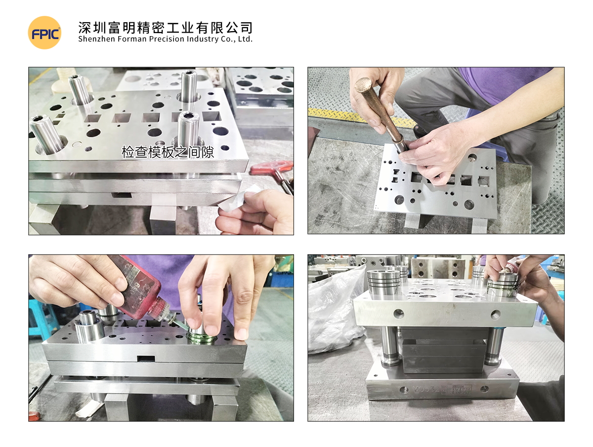
Before starting the assembly process, it is crucial to prepare the necessary tools, measuring instruments, and reference documents to ensure smooth execution.

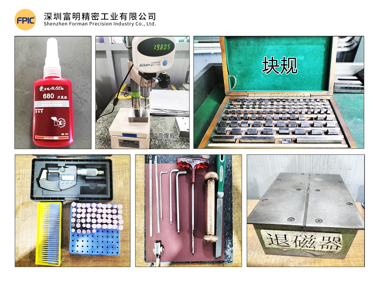
1. Tools & Measuring Instruments

Ensure that the required tools and measuring instruments are available, including:

  • Hand tools: Wrenches, files, copper hammers
  • Surface finishing tools: Oil stones, sandpaper, pneumatic grinders, polishing heads
  • Cleaning agents: Mold cleaner
  • Adhesives & lubricants: 680 glue
  • Measuring instruments: Vernier calipers, micrometers, gauge blocks, thin shims, demagnetizer, etc.mold tools

2. Understanding the Mold

Before assembly, review all relevant drawings:

  • Product drawings
  • Layout drawings
  • Mold part drawings

3. Mold Assembly Process Overview

Familiarize yourself with the entire mold assembly process:

  1. Main Plate Gluing (Clamping Plate + Stripper Plate + Bottom Plate)
  2. Template Assembly
  3. Clamping Plate Component Assembly
  4. Stripper Plate Assembly
  5. Bottom Plate Assembly
  6. Upper & Lower Mold Matching & Confirmation
  7. Mold Base Gluing (Upper & Lower Mold Base)
  8. Installation of Standard Components
  9. Trial Stamping & Sample Testing


II. Template & Component Inspection Before Assembly

1. Template Inspection

Material & Hardness Verification: Ensure templates have undergone deep-freezing and stabilization treatment.
Flatness & Warping Check: Warping should not exceed 0.005mm per 100mm.
Hole Position & Processing Accuracy: Verify drilled holes, allowances, and surface finish.
Screw Hole Depth & Alignment: Check threaded hole depth and perpendicularity for proper fastener fitment.
Embossing & Pressing Grooves: Ensure correct width and depth.
Labeling & Marking: Verify mold number, material width, pitch, and part name.

2. Component Inspection

  • Material, Quantity & Hardness Verification
  • Dimensional Accuracy Check

Proper inspection eliminates potential errors that could cause misalignment, improper fits, and structural weaknesses in the final mold.

III. Template Machining & Finishing

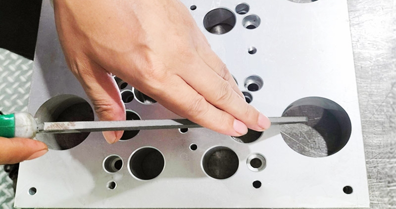
1. Mold Base Preparation

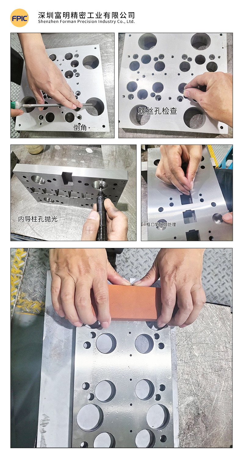
  • Clean all threaded holes of debris; check for damaged or unthreaded holes.
  • Deburr sharp edges and corners using a flat file.
  • Polish the surface with an oil stone to remove burrs.

2. Hole Deburring & Edge Rounding

  • Use round oil stones, files, grinders, and sandpaper for chamfering insert holes, round holes, and square holes.
  • Remove oxidation residues from wire-cut holes using fiber oil stones and round rods.

3. Surface Finishing

  • Polish the template with fine oil stones in the direction of the grinding pattern.
  • Use lubricating oil during polishing to prevent scratches.Mold Base & Template Finishing

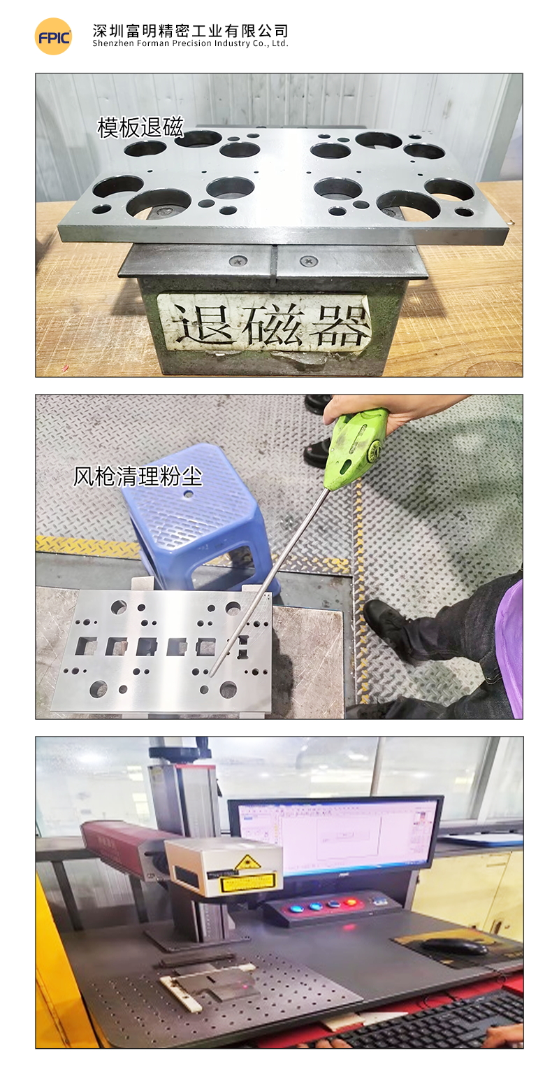
4. Demagnetization

  • Use a demagnetizer to remove magnetism from the mold base and all components to prevent iron powder absorption, which could affect assembly accuracy.

5. Cleaning

  • Clean templates thoroughly using mold cleaner and compressed air.
  • Precision mold assembly requires a high level of cleanliness to ensure optimal performance.

6. Component Handling

  • Engrave part numbers on components.
  • Add lead-in angles to guide posts.
  • Sort, match, and demagnetize all parts.mold cleaning

Tip: Precision molds require extreme cleanliness to prevent defects in stamped parts.

IV. Measurement & Alignment Verification

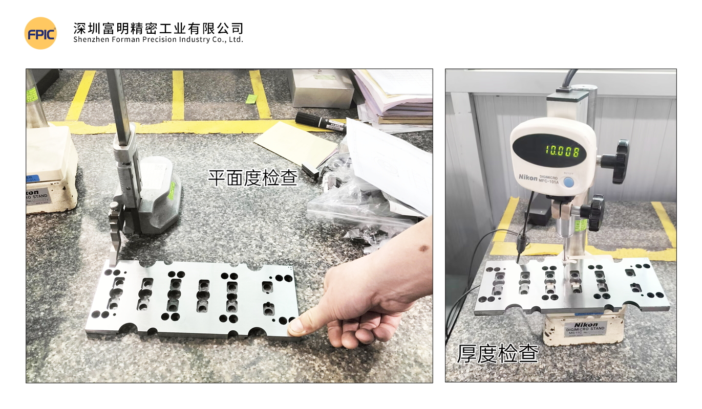
1. Template Parallelism Measurement

  • Fix a dial indicator to zero on a reference platform and measure.
  • Standard tolerance: ≤ 0.002mm.

2. Template Warping & Deformation Check

  • Press one end of the template and observe dial indicator changes at the other end.
  • Deformation should not exceed 0.003mm.

3. Main Template Parallelism & Warping Measurement

  • Tolerance should not exceed 0.005mm.

4. Guide Post & Guide Bushing Measurement

  • Ensure guide posts conform to the required dimensions and roundness.
  • Measure guide post fitment and machining accuracy per the drawings.Measurement & Quality Control

V. Mold Gluing Process

1. Gluing Steps

Step 1:

  • Use 0.005mm shims to check for gaps after mold closure.
  • The mold is qualified when shims cannot enter the gap.

Step 2:

  • After confirming the main template, insert a 10mm positioning pin from the clamping plate to the bottom plate to align the three primary templates.
  • If any gaps exist, check for debris or interference before proceeding.

Step 3:

  • Clean guide post and guide bushing thoroughly.
  • Insert guide posts into the stripper plate and secure with screws.
  • Place 0.2mm steel shims in each guide bushing hole.

Step 4:

  • Apply 680 glue evenly on the guide bushings while rotating them for even distribution.
  • Slowly insert guide bushings into the template until they rest against the steel shims.
  • Repeat for all guide bushings.Mold Gluing ProcessVI. Standard Component Assembly

1. Standard Component Inspection

  • Verify that all standard parts meet specifications.

2. Height & Position Check

  • Confirm the heights of floating pins, equal-height sleeves, limit posts, guide pins, and ejector rods.

3. Standard Component Installation

  • Clean all round holes before inserting components.
  • Install components into the mold cavity in order.

4. Final Confirmation

  • Ensure all parts are flat and properly fitted.
  • Verify free movement of standard components.
  • Check for clogged scrap ejection holes.
  • Ensure adjustment rods are correctly positioned and do not interfere with other templates.

VII. Mold Testing & Issue Documentation

1. Mold Closure Height Verification

  • Record closure height in the Mold Testing & Issue Report.

2. Manual Mold Closure Test

  • Close the mold manually to check for proper spring compression.

3. Trial Stamping & Sample Testing

  • Record initial data for comparison in subsequent trials.
  • Repeat trials until samples meet specifications.

4. Issue Analysis & Data Collection

  • Document all design & machining issues.
  • Analyze the root cause and record corrective actions.
  • Collect data for future design optimizations.

Example: Mold Testing & Issue Report

DateIssue DescriptionCorrective ActionDesign IssueMachining IssueResolution DateResultResponsible Person
2.18Tight-fitting D07 forming partWire-cut rework2.18NormalEngineer A
2.19S05 part causing ejection failureAdded ejector structure2.19NormalEngineer B
2.19Dimension 2.02mm undersizedAdded 0.02mm shim2.19NormalEngineer B
2.20Sent for FAI inspection2.20QA Inspector

 Note: All mold trials must be fully documented, ensuring a complete history of deviations and corrective actions.

Conclusion

The metal stamping mold assembly process requires precision, attention to detail, and strict quality control to ensure high-performance and long-lasting molds. By following these structured steps—from pre-assembly preparation to final testing—manufacturers can optimize efficiency, reduce downtime, and improve mold longevity.

Implementing these best practices will help ensure high-quality stamped parts, reducing waste, rework, and production costs.

Looking for High-Quality Metal Stamping Solutions?

At FPIC, we specialize in precision mold manufacturing with a focus on quality, efficiency, and innovation. Contact us today to learn more about our custom mold solutions!

Get in touch with us today!

Introduction: The Power of Push-Pull Connectors

In the world of high-performance connectors, every second counts, and every connection matters. Imagine an electro-mechanical connector that locks into place with precision, resists accidental disconnection, and withstands extreme environments—all while ensuring seamless high-speed data transmission and signal integrity. That’s exactly what a push-pull connector delivers.

Unlike traditional electrical connectors, push-pull connectors feature a self-locking connector mechanism that clicks securely into place with a simple push and releases effortlessly with a gentle pull. No twisting, no fumbling—just instant, quick-connect mechanism functionality. Used in cutting-edge medical device connectors, aerospace connectors, automotive connectors, and industrial connectors, these solutions thrive in the most demanding applications.

But what sets them apart? Why do engineers, manufacturers, and industry leaders swear by push-pull connectors? Whether dealing with high-voltage connectors, delicate fiber optic connectors, or rugged connectors for mission-critical electronics, choosing the right secure connection can mean the difference between flawless performance and catastrophic failure.

This guide breaks down everything you need to know—from how push-pull connectors work to selecting the perfect one for your needs. By the end, you’ll see why these compact connector design solutions are reshaping industries worldwide.

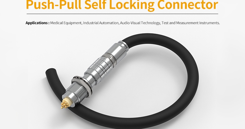
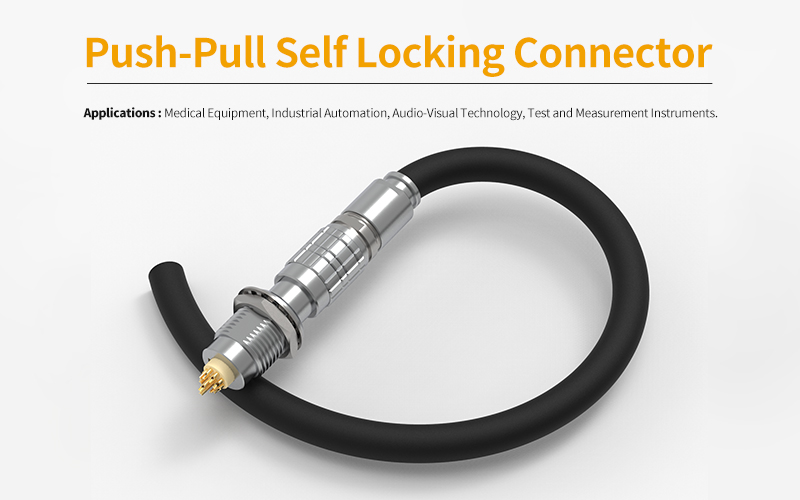
push pull connector

1. Understanding Push-Pull Connector Technology

1) How Does It Work?

A push-pull interconnect system is designed for effortless engagement and disengagement. Unlike traditional electrical connectors that require twisting or screwing, this quick-release connector operates through an internal locking system. When inserted, it automatically locks into place, preventing unintended disconnection. A simple pull of the outer housing releases the connection instantly, making it ideal for high-density connectors used in robotic system connectors and automation connectors.

2) What Makes It Unique?

  • Self-Locking Mechanism– Once engaged, it holds securely without additional latching or external force.
  • Quick Release Function– Designed for rapid disconnection, reducing downtime in high-speed operations.
  • Compact and Lightweight– A miniaturized connector solution perfect for PCB connectors and space-sensitive designs.
  • Secure and Reliable– Ensures connector durability and stability, even in harsh environment connectors where vibration or movement occurs.

3) Push-Pull vs. Traditional Connectors

FeaturePush-PullThreadedBayonet
Connection SpeedInstant lock & releaseTime-consumingModerate
Accidental Disconnection PreventionHighMediumMedium
Ease of UseSimple, one-hand operationRequires alignmentRequires rotation
Application SuitabilityHigh-frequency connectors, medical device connectors, industrial connectorsRugged environmentsModerate durability

This technology is essential for industries requiring fail-proof connectivity without compromising safety. Whether used in telecommunications connectors, automation connectors, or data center connectivity, its efficiency remains unmatched.

2. Key Features That Make Push-Pull Connectors Stand Out

1) Quick and Secure Engagement

Efficiency is at the core of this self-locking connector mechanism. A simple push engages the connector instantly, while an intentional pull releases it just as quickly. This foolproof locking system eliminates accidental disconnections, ensuring stability in vibration-resistant connectors used in medical devices, automotive systems, and industrial automation.

2) Long-Lasting Durability

Designed for high-cycle applications, these connectors endure over 5,000 mating cycles without performance degradation. This longevity makes them cost-effective, reducing maintenance and replacement costs in industries where connector durability is non-negotiable.

3) Space-Saving Compact Design

Miniaturization is a priority in modern engineering. These connectors provide a high-density connection solution while maintaining superior performance. Their small footprint is ideal for handheld medical instruments, wearable electronics, and compact industrial control systems.

4) Corrosion and Environmental Resistance

  • 1000-hour salt spray resistancefor high-humidity and corrosive environments
  • Operating temperature range of -55°C to 250°C, ensuring reliability in both extreme heat and cold
  • Sealed optionsfor dustproof and waterproof protection, making them suitable for outdoor and rugged applications

5) Optimized Electrical Performance

The use of 10U” thick gold plating on contacts enhances signal integrity and conductivity, minimizing resistance and power loss. Whether for high-speed data transmission, power distribution, or sensitive electronic circuits, these connectors provide uncompromised electrical performance.

Each of these features makes them the preferred choice for industries requiring precision, durability, and ease of use.

3. Types of Push-Pull Connectors and Their Applications

1) Standard Push-Pull Connectors

These are the most commonly used connectors, featuring a robust locking mechanism and versatile compatibility. They are ideal for:

  • Medical Equipment– MRI machines, diagnostic tools, and surgical devices
  • Industrial Automation– Sensors, actuators, and control systems
  • Laboratory Instruments– High-precision testing and measurement tools

2) High-Voltage Push-Pull Connectors

Designed for applications requiring power transmission without signal interference, these connectors offer:

  • Enhanced insulation to prevent arcing
  • High-voltage capacityfor power-demanding equipment
  • Reliable performance in automotive and energy storage systems

Common uses include electric vehicle power systems, battery management, and industrial power distribution.

3) Miniature Push-Pull Connectors

When space is a constraint, these compact connectors provide high-density solutions with maximum performance. Their key benefits include:

  • Lightweight and ergonomic design
  • Ideal for wearable medical devices and portable instruments
  • High-speed signal transmission with minimal interference

Applications: Hearing aids, handheld diagnostic devices, and drone electronics.

4) Fiber Optic Push-Pull Connectors

For industries that demand ultra-fast, high-bandwidth communication, fiber optic connectors offer:

  • Low signal attenuation for long-distance data transmission
  • Dustproof and waterproof sealing
  • Compatibility with advanced telecommunication systems

Used extensively in data centers, aerospace communications, and military-grade networking.

5) Hybrid Push-Pull Connectors

Combining electrical, fiber optic, fluidic, or pneumatic connections in a single interface, hybrid connectors:

  • Simplify complex wiring setups
  • Reduce the number of individual connections required
  • Enhance efficiency in multi-signal environments

Industries utilizing hybrid connectors include medical imaging systems, robotics, and automotive electronics.

With such a diverse range of push-pull connectors, selecting the right type depends on specific application needs, durability requirements, and environmental factors.

4. Where Are Push-Pull Connectors Used? Industry Insights

Push-pull connectors are a game-changer across multiple industries, providing secure, high-performance connections in environments where reliability is critical. Below are the key sectors that depend on them.

1) Medical Devices: Precision and Safety in Life-Saving Equipment

Medical applications demand zero-failure connectivity, making push-pull connectors the preferred choice. Their quick-mating, sterilization-ready, and compact design ensures uninterrupted functionality in:

  • MRI and CT scanners– Reliable signal transmission for imaging systems
  • Patient monitoring devices– Secure, error-free connections in life-support equipment
  • Surgical instruments– Sterilizable and lightweight connectors for handheld medical tools
  • Hearing aids and wearable devices– Miniature connectors for compact medical electronics

2) Aerospace & Defense: Engineered for Extreme Environments

In aviation and military applications, failure is not an option. Push-pull connectors withstand shock, vibration, extreme temperatures, and electromagnetic interference. Used in:

  • Military communication systems– High-reliability connections in battlefield equipment
  • Avionics and flight control systems– Ensuring precise data transfer for navigation
  • Satellite communication– High-frequency signal integrity for aerospace networks

3) Industrial Automation: Powering Smart Factories

Modern manufacturing relies on fast, durable, and efficient connectivity for automation. Push-pull connectors enhance:

  • Robotics and automated assembly lines– Quick connections for seamless operation
  • Sensor integration– Reliable data transmission in real-time monitoring
  • High-speed production machinery– Ensuring minimal downtime and high output efficiency

4) Automotive & E-Mobility: Driving Next-Gen Vehicles

With the rise of electric and autonomous vehicles, reliable power and data connections are essential. These connectors enable:

  • Battery management systems (BMS)– Secure connections for electric vehicle power modules
  • Charging infrastructure– High-current, robust solutions for EV fast charging
  • ADAS (Advanced Driver Assistance Systems)– Stable connectivity for smart driving technologies

5) Telecommunications: High-Speed Data Transmission

Push-pull connectors are integral to networking and telecommunication infrastructure, ensuring:

  • Fiber optic signal transmission– High-speed connectivity for 5G and broadband networks
  • Data center solutions– Secure, high-density cabling for cloud storage
  • Broadcasting and audio-visual equipment– Reliable signal integrity for professional media production

6) Renewable Energy: Enhancing Sustainable Power Solutions

In solar, wind, and battery storage applications, these connectors provide:

  • High-voltage and weather-resistant connectivity– Essential for solar inverters and wind turbines
  • Modular battery storage solutions– Scalable, secure connections for efficient energy distribution
  • Grid integration– Reliable power transmission in smart energy networks

Push-pull connectors are indispensable across these industries, offering fail-safe performance in critical environments. Selecting the right type ensures efficiency, longevity, and seamless connectivity in modern applications.

5. Choosing the Right Push-Pull Connector for Your Needs

Selecting the right connector is crucial to ensuring long-term reliability, efficiency, and safety in any application. The right choice depends on various factors, including electrical requirements, environmental conditions, and mechanical compatibility.

1) Key Factors to Consider

Before choosing a connector, evaluate the following:

Current & Voltage Rating – Ensure the connector meets the power and signal transmission requirements of your system.
Pin Configuration – Determine the number of contacts and their arrangement based on the complexity of your wiring system.
Material Composition – Choose between metal or plastic housing depending on the durability and weight requirements.
Size & Compactness – For space-constrained applications, opt for miniature push-pull connectors that maximize efficiency.
Sealing & Protection – If exposed to harsh environments, select connectors with IP-rated sealing for dust, moisture, and impact resistance.
Insertion & Extraction Cycle Durability – Ensure the connector can withstand at least 5,000 mating cycles for long-term reliability.

2) Matching the Connector with Your Cable Assembly

The right combination of connector and cable determines the overall performance. Consider:
? Cable gauge and insulation – Should match the electrical load to prevent overheating.
? Shielding requirements – For applications in data transmission, ensure connectors have EMI shielding to prevent signal interference.
? Flexibility vs. rigidity – Medical and robotics applications may require flexible, lightweight cables, while industrial use may demand reinforced, rigid cables.

3) Common Mistakes to Avoid When Selecting a Connector

? Overlooking environmental factors – Not accounting for temperature extremes, moisture, and vibration can lead to premature failure.
? Choosing a connector with excess or inadequate pin configurations – Leads to either unnecessary bulk or insufficient connectivity.
? Ignoring future scalability – If system expansions are likely, choose a modular connector that allows easy integration of additional circuits.
? Skipping thorough testing – Ensure connectors undergo electrical, mechanical, and environmental stress tests before final selection.

By carefully assessing these factors, businesses can reduce downtime, enhance operational efficiency, and ensure long-term reliability in their systems.

6. Installation and Maintenance Tips for Maximum Performance

Ensuring the proper installation and maintenance of push-pull connectors is critical for achieving optimal performance and longevity. Even the most advanced connectors can fail if not handled correctly. Follow these best practices to keep your connections secure, efficient, and long-lasting.

1) Step-by-Step Guide to Proper Installation

? Inspect the Connector and Cable – Before installation, check for visible damage, debris, or misaligned pins that may impact performance.
? Align and Insert Correctly – Push the connector straight into the socket without twisting or applying excessive force. The self-locking mechanism will engage automatically.
? Verify Secure Locking – A correctly installed connector should produce a click or tactile feedback, ensuring a firm connection.
? Avoid Over-Bending the Cable – Maintain the recommended bend radius to prevent stress on the internal wiring.
? Test Connectivity Before Finalizing Installation – Run an electrical or signal continuity test to confirm proper functioning.

2) How to Prevent Wear and Tear on Push-Pull Connectors

? Keep Connectors Clean – Dust and debris can interfere with contact integrity. Regular cleaning with compressed air or a lint-free cloth is recommended.
? Avoid Excessive Pulling or Tugging – Always disengage connectors using the designated release mechanism rather than pulling on the cable.
? Use Protective Caps When Not in Use – This prevents contaminants from affecting signal integrity, especially in dusty or wet environments.
? Store Connectors in a Dry, Temperature-Controlled Area – Extreme humidity or heat can degrade plastic insulation and metal contacts over time.

3) Best Practices for Long-Term Maintenance and Troubleshooting

✅ Perform Routine Inspections – Check for loose fittings, corrosion, or bent pins that may cause connection issues.
✅ Check for Signal or Power Drops – If experiencing data loss or power failure, inspect the contact points and cable continuity.
✅ Replace Worn-Out Connectors – If a connector has exceeded its insertion/extraction cycle limit, swap it out to maintain reliability.
✅ Keep Spare Connectors on Hand – Having backup units readily available can prevent costly downtime in critical applications.

Proper installation and proactive maintenance ensure push-pull connectors continue delivering stable, high-performance connections in mission-critical environments.

7. Push-Pull Connector Customization Options

Customization plays a key role in optimizing push-pull connectors for specific industry applications. From pin configurations to branding and packaging, tailoring connectors to unique requirements enhances efficiency, compatibility, and durability.

1) Custom Pin Configurations for Specialized Applications

Different industries demand unique pin layouts to accommodate power, signal, or hybrid transmission. Custom options include:
? Single and multi-pin configurations – Designed for low-voltage signals, high-power applications, or mixed data-power solutions.
? Coaxial or triaxial options – Ideal for RF and high-frequency transmission.
? Hybrid connectors – Combine electrical, fiber optic, fluidic, or pneumatic connections in a single housing.

2) Overmolding and Cable Assembly Solutions

Custom overmolding enhances mechanical strength, durability, and strain relief. Benefits include:
Improved resistance to moisture, dust, and chemicals for harsh environments.
Enhanced ergonomic handling for medical or wearable applications.
Strain relief protection to prevent cable fatigue and breakage.

3) Branding and Labeling Options for OEM Integration

Companies can customize connectors to align with branding and traceability requirements:
? Custom logo engraving – Helps in product identification and brand visibility.
? Unique color coding – Simplifies identification in multi-connector setups.
? QR code or serial number integration – Enables inventory tracking and quality assurance.

4) Push-Pull Connectors Designed for Extreme Environments

Some industries require ruggedized connectors built to withstand harsh operating conditions:
High-temperature resistance – Materials rated for -55°C to 250°C for aerospace and automotive applications.
Corrosion-proof coatings – 1000-hour salt spray resistance for offshore and military use.
High-pressure sealing – IP-rated waterproof designs for marine and medical autoclave sterilization.

5) How to Work with a Manufacturer for Custom Solutions

For businesses needing specialized connectors, working with an experienced connector manufacturer ensures:
? Tailored engineering support – From concept to production, ensuring optimal performance and compliance.
? Prototyping and testing – Verifying electrical, mechanical, and environmental performance before mass production.
? Scalable production capabilities – Supporting both small-batch and high-volume requirements.

Custom push-pull connectors allow businesses to optimize functionality, durability, and branding, ensuring seamless integration into high-performance applications.

8. The Future of Push-Pull Connector Technology

As industries evolve, so do their connectivity demands. Push-pull connectors are undergoing continuous innovation to meet the growing need for higher speed, greater durability, and smarter integration. Future developments focus on miniaturization, enhanced data transmission, and automation compatibility.

1) Miniaturization for High-Density Applications

With technology becoming smaller and more powerful, push-pull connectors are following suit. Advancements include:
Nano and micro push-pull connectors – Ideal for wearable medical devices, compact robotics, and aerospace instrumentation.
Lightweight materials – Designed to reduce weight in automotive and space applications without compromising strength.
High-density contact configurations – More signal paths within a smaller footprint for next-gen electronics.

2) High-Speed Data and Power Transmission

As 5G networks, IoT, and AI-driven systems expand, connectors must support faster, more efficient data transfer. Innovations include:
? Push-pull connectors optimized for fiber optics – Enhancing ultra-fast data transmission in networking and telecommunications.
? Higher power ratings in compact designs – Supporting electric vehicles, industrial automation, and energy storage.
? Low-loss, high-frequency connectors – Ensuring signal integrity in RF and high-speed computing applications.

3) Smarter, More Intelligent Connectors

The rise of smart technology is bringing intelligence to connectors, enabling real-time monitoring and automated diagnostics:
Self-monitoring connectors – Embedded sensors detect heat buildup, wear, or connectivity issues, reducing failure risks.
Automated locking and unlocking mechanisms – For robotic assembly lines and autonomous manufacturing.
Wireless push-pull connectors – Emerging technologies are exploring contactless power and data transfer, reducing mechanical wear.

4) Sustainability and Eco-Friendly Connector Innovations

With industries prioritizing sustainability, the next generation of connectors focuses on:
? Recyclable materials – Using biodegradable plastics and eco-friendly coatings for reduced environmental impact.
? Energy-efficient designs – Lowering power consumption in battery-powered and solar energy applications.
? Longer lifespan and modularity – Supporting repairability and component reusability instead of full replacements.

5) Industry Trends Shaping the Future of Push-Pull Connectors

The global demand for faster, smarter, and more rugged connectors is growing across industries:
Medical advancements – Miniature, sterilizable connectors for next-gen imaging, monitoring, and implantable devices.
Electric vehicle adoption – High-voltage, fast-charging connectors optimized for automotive energy storage.
Space and defense innovations – Ultra-durable connectors for deep-space exploration and military-grade technology.

The future of push-pull connectors is driven by cutting-edge materials, enhanced signal processing, and increased automation compatibility. As industries push for higher efficiency and reliability, these connectors will continue evolving to meet tomorrow’s technological needs.

9. Conclusion: Why Push-Pull Connectors Are the Best Choice

Push-pull connectors have become an essential component in modern technology, offering a fast, secure, and reliable solution for industries that demand precision and durability. Their self-locking mechanism, high-cycle durability, and superior resistance to environmental stress make them the go-to choice for critical applications.

Key Takeaways

✅ Instant & Secure Connection – The push-pull mechanism ensures a firm lock without accidental disconnections.
✅ Long-Lasting & Durable – With a lifespan of 5,000+ mating cycles, these connectors outperform traditional alternatives.
✅ Compact & High-Density – Ideal for space-constrained applications such as medical devices, robotics, and aerospace systems.
✅ Superior Electrical Performance – Optimized for high-speed data transmission, power delivery, and EMI shielding.
✅ Industry Versatility – Trusted in automotive, telecommunications, industrial automation, and military-grade applications.

As industries continue to evolve, push-pull connectors will remain at the forefront of connectivity solutions, adapting to new technologies and increasing performance standards. Whether you need custom configurations, high-speed data capabilities, or ruggedized solutions, these connectors provide unparalleled efficiency and reliability.

For businesses seeking cutting-edge interconnect solutions, partnering with a trusted push-pull connector manufacturer ensures the best performance for mission-critical applications. Invest in the right connector today for seamless, future-ready connectivity.

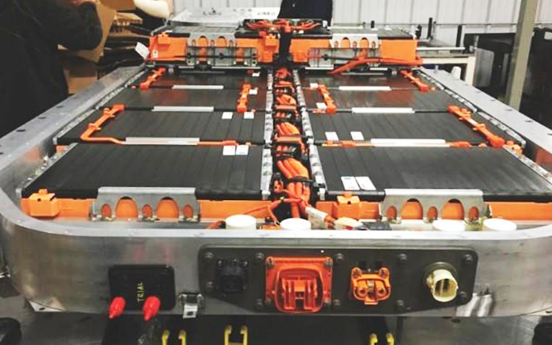
HVIL Connector application

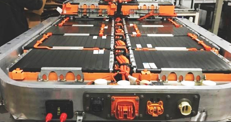
The HV800 HVIL (High Voltage Interlock) Connector is a critical component in high-voltage applications, particularly in sectors such as electric vehicles (EV), renewable energy systems, and industrial power applications. Specifically designed to meet the growing demand for safety, reliability, and performance in high-voltage systems, the HV800 HVIL connector offers innovative features that make it an excellent choice for various applications. In this article, we explore the primary applications for this connector and highlight the unique advantages offered by our HV800 HVIL connectors.

Key Applications of the HV800 HVIL Connector

1. Electric Vehicle (EV) Battery Systems

With the rapid advancement of electric vehicle technology, battery systems demand connectors that can support high-voltage and high-current requirements while ensuring driver and passenger safety. The HV800 HVIL connector is purposefully designed for EV battery packs, providing a secure and reliable high-voltage connection. The HVIL functionality is crucial in monitoring the integrity of high-voltage circuits, disconnecting power in the event of tampering or disconnection, and thus preventing potential hazards. The IP67-rated design of the HV800 HVIL connector ensures it remains free from water, dust, and other environmental contaminants, making it suitable for use in challenging automotive environments.

HVIL Connector application

2. Renewable Energy Systems

In renewable energy applications, such as solar power storage systems and wind energy equipment, high-voltage connectors are essential for handling the transmission of generated power. The HV800 HVIL connector supports the safe transmission of high-voltage power between storage systems and converters, while the HVIL feature enables critical monitoring and interlocking to prevent accidental disconnection. This capability not only enhances the safety of renewable energy systems but also ensures continuous and reliable energy supply, which is essential for uninterrupted power generation.

3. Industrial Power and Battery Storage Systems

In industrial environments, reliable power storage systems are critical for ensuring efficient operation, minimizing downtime, and enhancing productivity. The HV800 HVIL connector is ideal for high-power industrial applications that require durable and stable connections for high-voltage batteries and storage units. With its high current rating and interlocking capabilities, this connector provides both stability and protection in industrial power systems, preventing potential failures and ensuring smooth operational continuity.

4. Heavy-Duty Equipment and Off-Highway Vehicles

Heavy-duty vehicles, such as mining trucks, agricultural equipment, and construction machinery, are increasingly incorporating electric powertrains. The HV800 HVIL connector’s robust design and high IP rating make it suitable for use in such rugged and demanding environments. Its ability to handle high currents and voltages, combined with HVIL safety features, ensures that these heavy-duty applications operate safely and effectively under extreme conditions.

Unique Advantages of the HV800 HVIL Connector

At FPIC, we take pride in our HV800 HVIL connector’s engineering excellence and attention to detail. Here are some of the key advantages that set our product apart:

1. Robust and Stable Connectivity

The HV800 HVIL connector is specifically designed to ensure stable and secure connections. Its high-strength construction and IP67 rating protect it from environmental elements such as dust, moisture, and extreme temperatures. This robust design guarantees long-term reliability, making it suitable for use in high-demand applications such as EV battery systems and industrial power storage.

2. Safety and Compatibility

Safety is at the core of the HV800 HVIL connector’s design. The high-voltage interlock (HVIL) feature provides an additional layer of safety by monitoring the connector’s integrity and disconnecting the circuit if the connector is tampered with or disconnected. Additionally, the HV800 HVIL connector can accommodate a range of wire sizes, making it versatile for various power levels and ensuring compatibility with different system requirements.

3. End-to-End Manufacturing Excellence

As an industry-leading manufacturer, FPIC is committed to delivering quality at every stage of production. We provide end-to-end service that encompasses product design, mold design and manufacturing, component fabrication, automated assembly, rigorous testing, and packaging. This integrated approach allows us to maintain strict quality control across the entire production process, ensuring that every HV800 HVIL connector meets the highest standards for durability, performance, and safety.

4. High Current and Voltage Capabilities

The HV800 HVIL connector is rated for high current and voltage applications, supporting up to 850V DC. Its 8mm contact pin diameter and silver-plated contacts ensure excellent conductivity and reduced contact resistance, making it ideal for applications that require substantial power transfer with minimal energy loss.

5. Customization and Technical Support

We understand that every application is unique. That’s why FPIC offers customized solutions to meet specific project requirements. Our expert engineering team works closely with clients to adapt our HV800 HVIL connectors to their application’s particular needs, including connector configurations, material selection, and assembly methods. We also provide technical support throughout the project to ensure seamless integration and optimal performance.

Conclusion

The HV800 HVIL connector stands as a vital solution for high-voltage applications, combining durability, safety, and adaptability. Its extensive application in electric vehicles, renewable energy systems, industrial power storage, and heavy-duty machinery highlights its versatility and reliability. At FPIC, we remain committed to advancing connector technology and setting industry benchmarks for safety and performance. Our HV800 HVIL connector embodies our dedication to engineering excellence and customer satisfaction.

As we look toward the future, we continue to drive innovation and expand our range of high-voltage solutions. Whether you’re an automotive manufacturer, renewable energy provider, or industrial equipment producer, FPIC’s HV800 HVIL connectors are engineered to meet the rigorous demands of modern power systems. For further inquiries and to explore how our HV800 HVIL connectors can enhance your application, please reach out to our team. Let us be your trusted partner in high-voltage connectivity solutions.