Tag Archive for: Circular connectors

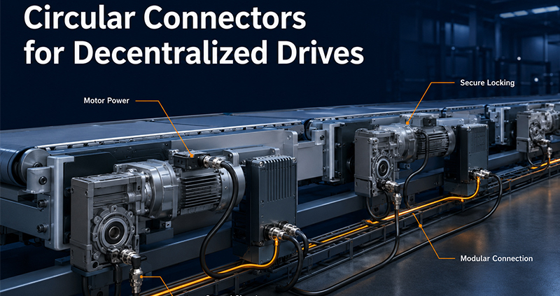
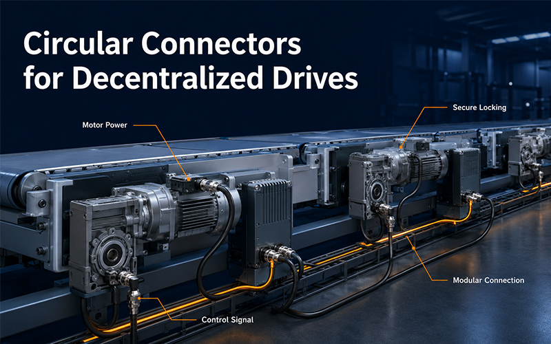
Circular Connectors for Decentralized Drives

Industrial automation is moving away from architectures in which every motor, sensor, and actuator is wired directly back to one central control cabinet.

More drives, controllers, I/O modules, and power-distribution functions are now installed closer to the machine process. This reduces long cable routes and supports modular equipment design, but it also places greater demands on the connectors used at the device level.

Quick Answer:

Circular connectors support decentralized drive systems by providing compact and secure interfaces for motor power, control signals, communication, and protective earth. Their standardized mating interfaces, reliable locking, environmental protection, and cable-assembly flexibility help simplify installation and maintenance.

The connector should not be selected only by diameter or pin count. Engineers must also evaluate voltage, current, conductor size, signal type, shielding, cable movement, environmental exposure, and the required maintenance strategy.


Why Drive Systems Are Becoming More Decentralized

In a traditional centralized architecture, motor starters, frequency converters, I/O modules, and control devices are usually installed inside a large electrical cabinet. Power and signal cables then run from that cabinet to each device on the machine.

A decentralized system moves some of these functions closer to the motor or production process.

Typical equipment may include:

  • decentralized motor starters;
  • compact drive controllers;
  • variable-frequency drives installed near motors;
  • remote I/O modules;
  • distributed sensor and actuator hubs;
  • machine-mounted power-distribution units;
  • modular conveyor and material-handling systems.

This architecture can reduce cabinet size, shorten field wiring, and allow machine modules to be assembled and tested separately.

However, decentralization also exposes connection points to vibration, dust, moisture, oil, cable movement, and repeated maintenance. The electrical interface therefore becomes a critical part of the machine architecture.

HARTING’s recent Size 15 circular connector announcement reflects this direction. The company positions the interface for asynchronous motors, decentralized control systems, and daisy-chain applications where compact size, standardization, and secure locking are important.

Circular Connectors Combine Multiple Functions in Limited Space

Installation space around motors and decentralized controllers is often restricted.

A connector may need to fit between:

  • the motor housing;
  • gearbox;
  • brake;
  • encoder;
  • local controller;
  • machine frame;
  • cable-routing system.

Circular housings offer a compact interface with good mechanical strength. Depending on the configuration, one interface can carry power, protective earth, brake control, temperature-sensor signals, encoder signals, or communication circuits.

Common arrangements include:

  • power contacts with protective earth;
  • power plus auxiliary signal contacts;
  • signal-only multipole configurations;
  • hybrid power, signal, and data layouts;
  • separate connectors for motor power, feedback, and communication.

HARTING’s Size 15 standard includes configurations for 630 V/16 A, 48 V/20 A, and 24 V/20 A applications. The company states that its supported variants can be used for daisy-chain systems up to 16 kW or asynchronous motors up to 7.5 kW, depending on the selected interface and application conditions.

These values describe one manufacturer’s standardized platform. They should not be applied automatically to other products. Every connector must be selected according to its own datasheet, conductor specification, ambient conditions, and validation results.

Standardized Interfaces Support Modular Machine Design

Standardization becomes more important when equipment manufacturers build modular machines or operate global production sites.

A standardized mating interface can help support:

  • repeatable machine-module design;
  • replacement of motors or controllers;
  • cross-manufacturer compatibility;
  • second-source planning;
  • easier spare-parts management;
  • simplified field-service procedures.

HARTING identifies IEC 61076-2-115 as the standard governing its Size 15 interface and highlights cross-manufacturer compatibility as a benefit for industrial automation users.

Other common industrial circular interfaces include M8, M12, M17, M23, and larger industrial formats. Each size supports a different balance of contact count, cable cross-section, current capacity, power level, shielding, and installation space.

The correct objective is not to choose the smallest connector available. It is to choose the smallest standardized or customized interface that can reliably support the required electrical and mechanical conditions.
Circular Connectors for Decentralized Drives

Reliable Locking Protects Connections Under Vibration

Motors, conveyors, pumps, fans, compressors, and robotic equipment generate continuous vibration and repeated mechanical movement.

If the mating interface is not securely locked, vibration can cause:

  • micro-movement between contacts;
  • increasing contact resistance;
  • intermittent signals;
  • shield discontinuity;
  • seal movement;
  • complete disconnection.

Industrial circular connectors use several locking methods.

Locking methodMain benefitKey consideration
Threaded couplingStable, familiar, suitable for vibrationInstallation time and correct tightening
Bayonet lockFast mating and clear locking movementCorrect rotation and lock engagement
Push-pull lockVery fast installation and removalRetention structure and application suitability
Quick-lock threadCombines speed with circular couplingCompatibility with the selected series
Screw or flange mountingStable equipment-side installationPanel strength and mounting torque

HARTING uses a bayonet lock for its Size 15 interface, describing it as a fast and vibration-resistant solution for industrial environments.

For FPIC projects, locking should be selected according to vibration level, mating frequency, available service space, required installation speed, and customer-defined retention requirements.


Power and Signal Requirements Must Be Evaluated Together

Decentralized drive interfaces may transmit both energy and control information.

Typical circuits can include:

  • three-phase motor power;
  • DC power;
  • protective earth;
  • brake control;
  • temperature monitoring;
  • encoder feedback;
  • sensor signals;
  • industrial Ethernet or fieldbus communication.

A connector that can physically accommodate all required contacts is not automatically suitable.

Engineers should review:

  • system voltage;
  • continuous and peak current;
  • number of simultaneously energized contacts;
  • conductor cross-section;
  • permitted voltage drop;
  • temperature rise;
  • creepage and clearance requirements;
  • signal frequency or data rate;
  • isolation between power and signal contacts;
  • protective-earth connection sequence.

When power and signal contacts share one connector, contact allocation becomes especially important. Noisy power circuits should not be placed without consideration next to sensitive feedback or communication signals.

Depending on the drive architecture, separate power and signal connectors may provide better signal integrity and easier troubleshooting. In other systems, a hybrid interface may reduce installation space and cable count.


Shielding Depends on the Motor and Control Architecture

Not every decentralized motor connection requires the same electromagnetic shielding.

HARTING notes that its Size 15 product is mainly intended for asynchronous drives that do not require frequency control, allowing the use of a robust plastic housing instead of a more complex shielded metal enclosure.

This distinction is important.

When a variable-frequency drive controls the motor, fast switching edges can generate electromagnetic interference. In such cases, engineers may need:

  • shielded motor cable;
  • 360-degree shield termination;
  • conductive connector housing;
  • low-impedance connection to the motor enclosure;
  • controlled grounding at the converter and motor;
  • separation from sensitive signal circuits.

Metal circular housings can provide EMC shielding when the housing, cable braid, connector shield, and equipment enclosure form a continuous conductive path. HARTING also identifies metal housings as a means of shielding against electromagnetic interference in industrial circular connector systems.

For an unshielded asynchronous motor, a plastic connector may reduce weight and cost. For servo drives, variable-frequency motors, encoders, or communication circuits, shielding requirements may be much more demanding.

The decision should follow the complete electrical architecture rather than a general rule that metal is always better.

Daisy-Chain Connections Can Simplify Field Wiring

In some decentralized systems, several low-power motors, controllers, or devices are connected in sequence.

This is commonly called a daisy-chain arrangement.

Instead of running one separate supply cable from the main cabinet to every device, power enters the first unit and continues to the next units through additional connectors.

Potential benefits include:

  • fewer long cable runs;
  • reduced cabinet wiring;
  • cleaner machine layout;
  • faster module installation;
  • easier expansion.

However, daisy chaining must be engineered carefully.

The upstream connector and conductor may carry the combined current of all downstream devices. Engineers must therefore calculate:

  • total connected load;
  • startup or inrush current;
  • voltage drop across the complete chain;
  • current through each upstream interface;
  • conductor size;
  • protection-device coordination;
  • permitted number of connected devices;
  • failure behavior if one unit is disconnected.

A connector suitable for one motor may not be suitable for the combined current of multiple motors.


Custom Cable Assemblies Complete the Connection System

The connector and cable should be designed as one assembly.

A technically suitable connector can still perform poorly when paired with the wrong conductor, shield, jacket, bend radius, or strain-relief method.

1. Conductor Size

The cable cross-section must support the continuous and peak load without excessive voltage drop or temperature rise.

The terminal barrel must also match:

  • conductor material;
  • wire cross-section;
  • strand class;
  • insulation diameter;
  • crimp geometry.

2. Core Count

The required core count depends on the drive architecture.

Typical combinations may include:

  • three power conductors plus protective earth;
  • motor power plus brake wires;
  • power plus temperature sensing;
  • separate feedback or encoder cable;
  • hybrid power-and-signal cable.

3. Shielding

Shielding should be defined according to the interference source and the sensitivity of nearby circuits.

Possible constructions include:

  • overall braided shield;
  • foil plus drain wire;
  • individually shielded signal pairs;
  • separate power and signal shielding;
  • 360-degree shield termination at the connector.

4. Jacket Material

The outer jacket should match the installation environment.

Common factors include:

  • oil resistance;
  • abrasion resistance;
  • coolant exposure;
  • flame behavior;
  • UV resistance;
  • operating temperature;
  • halogen-free requirements;
  • indoor or outdoor use.

5. Flexing and Torsion

A cable installed on a stationary motor has different requirements from one routed through a drag chain, robotic joint, rotating table, or moving gantry.

Dynamic applications may require validation for:

  • repeated bending;
  • torsional movement;
  • minimum bend radius;
  • acceleration;
  • travel length;
  • cycle life.

FPIC supports industrial circular connectors and customized cable assemblies for equipment applications. Internal company materials identify industrial connector features including stable threaded mating, vibration resistance, IP67-level protection for applicable designs, shielding options, and operating-temperature considerations. FPIC also manufactures industrial wire harnesses and complete connector-and-cable solutions.


Connector Installation Must Match the Equipment Layout

The installation method affects both production efficiency and long-term reliability.

Common equipment-side options include:

  • front-panel flange mounting;
  • rear-panel mounting;
  • threaded panel receptacles;
  • bulkhead feedthroughs;
  • PCB-mounted receptacles;
  • direct mounting on a motor or controller housing.

Cable-side options may include:

  • field-attachable connectors;
  • crimped cable connectors;
  • soldered terminations;
  • overmolded assemblies;
  • preassembled cable sets.

Overmolded cable assemblies can provide controlled strain relief and environmental sealing. Field-attachable connectors may offer more installation flexibility but require consistent conductor preparation and assembly control.

The equipment layout should allow sufficient space for:

  • connector mating;
  • lock operation;
  • cable bending;
  • technician access;
  • inspection;
  • disconnection during maintenance.

A compact connector does not create a compact installation when the cable is forced into an unsuitable bending radius.


Maintainability Should Be Defined Early

One of the main benefits of decentralized architecture is modular replacement.

A faulty motor, controller, or machine module can potentially be removed without rewiring the complete system.

Circular connectors support this strategy when they provide:

  • clear coding;
  • polarity protection;
  • reliable locking;
  • visible or tactile mating confirmation;
  • accessible release mechanism;
  • replaceable cable assemblies;
  • consistent interface definitions.

Coding is especially important when several similar connectors are installed close together. Different mechanical coding, contact arrangements, identification colors, or labels can reduce incorrect mating.

HARTING notes that circular connector coding helps prevent mismating and that standardized mating faces support compatibility across industrial applications.

Maintenance planning should also define whether the interface may be disconnected under load. Most motor and power connectors are not switching devices and should only be disconnected after the system has been safely isolated.

Environmental Conditions Determine Housing and Sealing

Decentralized equipment places connectors outside the protected cabinet.

The interface may be exposed to:

  • dust;
  • oil;
  • coolant;
  • water spray;
  • humidity;
  • temperature changes;
  • vibration;
  • accidental impact;
  • cleaning chemicals.

The required protection level should be specified for both the mated and unmated condition.

Engineers should verify:

  • IP rating;
  • seal material;
  • permitted cable diameter;
  • operating temperature;
  • chemical compatibility;
  • salt-spray requirements;
  • UV exposure;
  • washdown conditions;
  • connector-cap requirements when unmated.

HARTING describes industrial circular connectors as suitable for protecting connections from dust, dirt, grease, oils, moisture, vibration, and movement.

The final product rating still depends on correct assembly, cable diameter, mounting, sealing, and use of the specified accessories.


A Practical Selection Checklist

Before selecting a circular connector for a decentralized drive, define the following information.

Design areaRequired information
Drive typeAsynchronous motor, servo, VFD-controlled motor, actuator
System architecturePoint-to-point, daisy chain, remote I/O, modular machine
VoltageNominal voltage, maximum voltage, AC or DC
CurrentContinuous, peak, startup current, duty cycle
ContactsPower, PE, brake, temperature, signal, and data circuits
CableCore count, conductor size, shield, jacket, outer diameter
EMCUnshielded, overall shield, 360-degree termination
LockingThreaded, bayonet, push-pull, or quick-lock
EnvironmentDust, water, oil, chemicals, temperature, vibration
InstallationPanel, motor housing, controller, field assembly, overmolding
MovementFixed, flexing, drag-chain, torsion, robotic motion
MaintenanceMating cycles, service access, coding, replacement method
ComplianceIEC, UL, customer specifications, regional requirements

This information allows the connector manufacturer to evaluate the complete interface rather than simply matching a pin count.


From Prototype Validation to Repeat Production

A customized drive-connection project should move through controlled engineering and production stages.

Requirement Review

The connector and cable should be reviewed against the motor, controller, power architecture, signal requirements, installation space, and environmental conditions.

Prototype Development

Prototype samples allow the customer to verify:

  • fit;
  • routing;
  • mating access;
  • cable length;
  • electrical continuity;
  • shielding;
  • machine integration.

Electrical Validation

Depending on the project, testing may include:

  • contact resistance;
  • insulation resistance;
  • dielectric withstand;
  • voltage drop;
  • temperature rise;
  • continuity;
  • short-circuit checks.

Mechanical Validation

Relevant tests may include:

  • insertion and extraction force;
  • terminal retention;
  • cable pull force;
  • vibration;
  • mechanical shock;
  • flexing or torsion.

Environmental Validation

Depending on the application:

  • temperature cycling;
  • thermal shock;
  • humidity;
  • salt spray;
  • waterproof testing;
  • chemical exposure.

Production Control

Repeat production requires more than an approved sample.

The manufacturing process should control:

  • terminal and wire combinations;
  • crimp height;
  • conductor position;
  • pull force;
  • assembly sequence;
  • connector locking;
  • electrical testing;
  • traceability.

FPIC’s internal capability materials list contact-impedance, temperature-rise, insulation, withstand-voltage, insertion-force, vibration, thermal-shock, dimensional, X-ray, and cable-harness testing equipment. The company also uses automated assembly and CCD-supported inspection in applicable connector production.

These capabilities allow the validation plan to be defined according to the product, application, customer specification, and approved acceptance criteria.


How FPIC Supports Decentralized Drive Connections

FPIC provides circular connectors, industrial cable assemblies, terminals, plastic housings, metal components, and customized interconnection development.

Support for decentralized motor and equipment projects can include:

  1. connector and cable architecture review;
  2. pin-count and contact-layout development;
  3. power and signal integration;
  4. conductor and terminal matching;
  5. shielding and grounding structure review;
  6. housing, locking, and keying customization;
  7. cable-jacket and movement-requirement selection;
  8. mold, stamping, and assembly-process development;
  9. prototype manufacturing;
  10. electrical and mechanical verification;
  11. automated production and repeat-production support.

FPIC’s circular connector direction includes threaded and push-pull structures for industrial applications, while its broader manufacturing platform covers tooling, stamping, injection molding, insert molding, cable processing, automated assembly, and testing.

The appropriate solution should be selected according to the actual motor, controller, equipment layout, electrical load, and operating environment.


Frequently Asked Questions

1. Why are circular connectors suitable for decentralized drives?

Their compact shape, secure locking, environmental protection, coding options, and ability to carry power and signals make them suitable for machine-mounted motors, controllers, and distributed I/O.

2. Can one connector carry motor power and control signals?

Yes, when the contact layout, insulation, current capacity, signal integrity, thermal behavior, and EMC requirements are correctly engineered. Some applications may still perform better with separate interfaces.

3. Does every motor connector need a metal shield?

No. Uncontrolled or fixed-speed asynchronous motors may use an unshielded interface. VFD-controlled motors, servos, encoders, and communication circuits may require metal housings and 360-degree shielding.

4. What cable information is needed for connector selection?

Provide conductor size, core count, system voltage, continuous and peak current, shielding, outer diameter, jacket material, bending radius, and whether the cable is fixed or continuously moving.

5. Are circular connectors suitable for daisy-chain systems?

Yes, but engineers must calculate the combined downstream current, voltage drop, protection coordination, conductor size, and maximum number of connected devices.

6. What files should be provided for a customized project?

Provide 2D or 3D drawings, motor and controller specifications, pin assignment, cable requirements, installation space, operating conditions, annual volume, and required validation standards.


Conclusion

Circular connectors help decentralized drive systems combine compact installation, standardized interfaces, reliable locking, environmental protection, and modular maintenance.

Their value depends on more than connector size. Reliable system design requires the connector, terminal, cable, shielding, mounting method, and validation plan to be developed together.

For equipment manufacturers, this integrated approach supports faster installation, easier module replacement, and more consistent repeat production.

Discuss Your Drive Connection Project

FPIC supports customized circular connectors and industrial cable assemblies for motors, controllers, sensors, automation equipment, and modular machine systems.

Send your drawings, electrical requirements, cable specification, operating conditions, and forecast demand for engineering review.

Email: info@fpiconn.com


Resources

  • HARTING Technology Group. Size 15 Circular Connectors: An Efficient Interface for Decentralised Drive Systems. April 20, 2026.
  • HARTING Technology Group. Circular Connectors: Selection, Coding, Locking and Industrial Applications.
  • HARTING Technology Group. Metric Circular Connectors.
  • HARTING Technology Group. M12 PowerX for Compact Decentralized Applications.
  • HARTING Technology Group. M17 Circular Connectors for Modern Drive Applications.
Circular Connector Applications Across Industries

Circular connectors are widely used because they combine compact size, reliable electrical performance, and excellent environmental protection. From medical imaging systems and industrial robots to outdoor automation and renewable energy equipment, they provide dependable connections for power, signal, and data transmission.

However, there is no universal circular connector suitable for every application. A connector designed for a surgical device may not survive on construction machinery, while an outdoor waterproof connector may be unnecessarily large for laboratory equipment.

Selecting the right connector requires balancing electrical performance, environmental protection, mechanical reliability, and maintenance requirements.

This guide explains the most important factors engineers should consider when choosing circular connectors for different industries.

Circular Connector Applications Across Industries


Start with the Application Environment

Before comparing connector specifications, first understand where the connector will operate.

Typical environments include:

Medical Equipment

  • Diagnostic systems
  • Patient monitoring devices
  • Surgical equipment
  • Laboratory instruments

Design priorities:

  • Compact size
  • Frequent cleaning
  • High mating reliability
  • Excellent signal integrity

Industrial Automation

Typical applications include:

  • Industrial robots
  • Servo motors
  • PLC control systems
  • Machine tools
  • Factory automation

Design priorities:

  • Vibration resistance
  • EMC performance
  • High mating durability
  • Reliable locking

Outdoor Equipment

Typical applications include:

  • Renewable energy systems
  • Agricultural machinery
  • Construction equipment
  • Rail transportation
  • EV charging infrastructure

Design priorities:

  • Waterproof sealing
  • UV resistance
  • Corrosion resistance
  • Wide operating temperature

Different environments require different connector designs.


Choose the Appropriate Locking Mechanism

Connector locking directly affects operational reliability.

Common options include:

Push-Pull Locking

Advantages:

  • Fast connection
  • One-hand operation
  • Easy maintenance
  • Secure automatic locking

Ideal for:

  • Medical equipment
  • Laboratory systems
  • Collaborative robots

Threaded Locking

Advantages:

  • Excellent vibration resistance
  • Strong mechanical retention
  • Long-term stability

Ideal for:

  • Industrial automation
  • Servo systems
  • Heavy equipment

Bayonet Locking

Advantages:

  • Quick quarter-turn locking
  • Reliable positioning
  • Outdoor suitability

Ideal for:

  • Portable equipment
  • Field instruments
  • Mobile machinery

Consider Environmental Protection

Environmental sealing is critical when connectors are exposed to dust, water, oil, or cleaning chemicals.

Common protection levels include:

IP Rating                Typical Applications

IP67                         Industrial automation, robotics

IP68                        Outdoor automation, renewable energy

IP69K                      Food processing, washdown equipment, heavy-duty vehicles

The required protection level should match the actual operating conditions rather than simply selecting the highest rating available.


Evaluate EMC Requirements

Modern equipment often combines:

  • Power transmission
  • Industrial Ethernet
  • CAN Bus
  • High-speed data
  • Precision sensors

Shielded circular connectors help:

  • Reduce EMI
  • Improve signal integrity
  • Maintain communication stability
  • Support reliable automation

For high-speed communication, connector shielding should include proper 360° shield termination.


Select the Right Contact Configuration

Connector selection also depends on:

  • Number of contacts
  • Signal type
  • Power rating
  • Mixed power and signal transmission

Many applications combine:

  • Power contacts
  • Signal contacts
  • Data contacts
  • Ground contacts

Hybrid connectors simplify installation while reducing cable complexity.


Consider Mating Cycle Requirements

Some connectors remain installed for years.

Others are connected and disconnected daily.

Typical examples include:

Low Mating Frequency

  • Wind turbines
  • Energy storage systems
  • Control cabinets

High Mating Frequency

  • Medical devices
  • Test equipment
  • Portable instruments

Applications with frequent reconnection should prioritize connectors designed for thousands of mating cycles.


Material Selection Matters

Connector housing materials influence durability and EMC performance.

Common choices include:

Metal Housing

Advantages:

  • Better shielding
  • Higher mechanical strength
  • Improved heat dissipation

Engineering Plastic Housing

Advantages:

  • Lightweight
  • Corrosion resistant
  • Cost-effective

Material selection should reflect the environmental and mechanical demands of the application.


Validate Before Production

Connector selection should always be verified through testing.

Recommended evaluations include:

  • Mating cycle testing
  • Vibration testing
  • Salt spray testing
  • IP protection testing
  • Contact resistance testing
  • EMC verification
  • Temperature cycling

Testing complete connector assemblies under actual operating conditions provides the highest confidence in long-term performance.


How FPIC Supports Circular Connector Applications

FPIC develops circular connectors, push-pull self-locking connectors, waterproof connectors, and customized connectivity solutions for medical equipment, industrial automation, robotics, renewable energy, and outdoor applications.

With more than 23 years of manufacturing experience, our engineering team helps customers select the right connector based on electrical performance, environmental requirements, mechanical reliability, and application-specific standards. From prototype development to mass production, FPIC provides dependable connector solutions designed for long-term performance.


Final Thoughts

Choosing the right circular connector involves much more than selecting the correct number of contacts.

Engineers must consider the operating environment, locking mechanism, environmental sealing, EMC performance, durability, and maintenance requirements together

Whether designing a medical device, an industrial robot, or an outdoor energy system, selecting the appropriate connector improves equipment reliability, simplifies maintenance, and reduces lifecycle costs.


FAQ

What factors should be considered when choosing a circular connector?

Key factors include application environment, IP protection, locking mechanism, shielding, contact configuration, mating cycles, and environmental durability.

Which locking mechanism is best for medical equipment?

Push-pull connectors are widely used in medical equipment because they provide fast, secure, one-handed operation and support frequent mating cycles.

Is IP69K always better than IP67?

Not necessarily. The appropriate IP rating should match the operating environment. Higher protection levels may increase size and cost without adding practical benefits.

When are shielded circular connectors required?

Shielded connectors are recommended for applications involving Industrial Ethernet, CAN Bus, servo systems, or environments with significant electromagnetic interference.

Why is mating cycle life important?

Applications requiring frequent connection and disconnection need connectors with high mating durability to maintain reliable electrical performance over time.


Looking for the Right Circular Connector for Your Application?

Whether you’re designing medical equipment, industrial automation systems, or outdoor electrical installations, FPIC provides high-quality circular connectors, push-pull self-locking connectors, and waterproof connectivity solutions tailored to your application. Our engineering team can help you select the ideal connector for reliable performance in demanding environments.

Contact FPIC today to discuss your circular connector requirements.


Resources

  1. IEC 61076 – Connectors for Electrical and Electronic Equipment
    https://webstore.iec.ch/
    Provides international standards for the design, performance, and testing of circular and industrial connectors.
  2. IEC 60529 – Degrees of Protection Provided by Enclosures (IP Code)
    https://webstore.iec.ch/
    Defines IP67, IP68, and IP69K protection ratings for connectors used in industrial and outdoor environments.
  3. IEC 60601-1 – Medical Electrical Equipment
    https://webstore.iec.ch/
    Specifies general safety and essential performance requirements for medical electrical equipment, including connector-related considerations.
  4. Phoenix Contact – Circular Connectors for Industrial Applications
    https://www.phoenixcontact.com/
    Provides technical information on circular connector selection, industrial connectivity, and environmental protection.
  5. TE Connectivity – Circular Connector Solutions
    https://www.te.com/
    Offers engineering resources on circular connectors for medical devices, industrial automation, transportation, and energy applications.
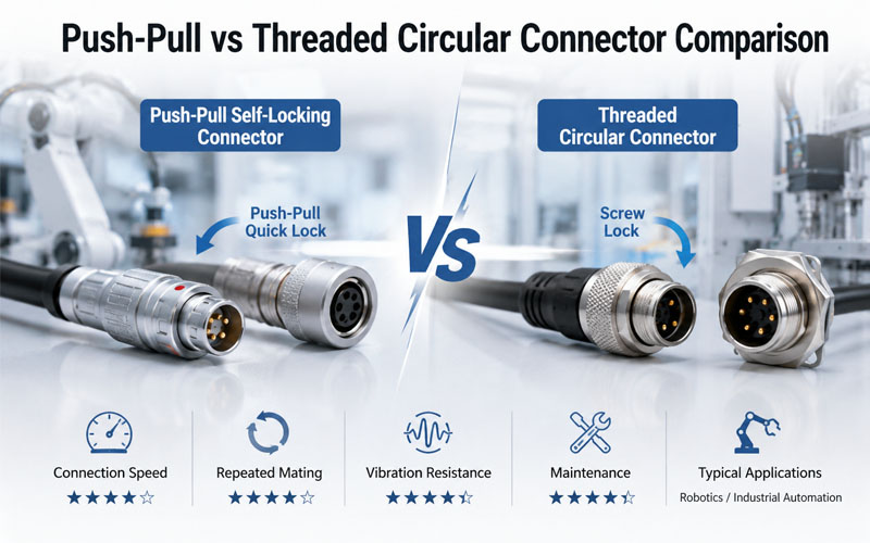
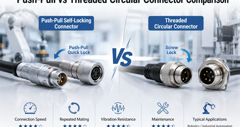
Push-Pull vs Threaded Circular Connectors Comparison

Circular connectors are widely used in industrial automation, robotics, medical devices, test equipment, and communication systems because they provide reliable electrical connections in demanding environments.

Two of the most common locking mechanisms are push-pull and threaded connectors. Both offer excellent electrical performance, but they are designed for different operating priorities.

When connectors are frequently connected and disconnected during equipment maintenance, tool changes, or production testing, the locking mechanism becomes just as important as the electrical specifications.

This article compares push-pull and threaded circular connectors from the perspective of repeated mating performance, helping engineers choose the right solution for long-term reliability.

Push-Pull vs Threaded Circular Connectors Comparison


Understanding the Two Locking Mechanisms

Although both connector types perform the same basic function, their locking principles are very different.

Push-Pull Connectors

Push-pull connectors automatically lock when inserted and can be released with a simple pull on the outer sleeve.

Key characteristics include:

  • One-handed operation
  • Automatic self-locking
  • Fast connection and disconnection
  • Compact structure
  • Reduced installation time

They are commonly used in:

  • Collaborative robots
  • Medical devices
  • Test equipment
  • Portable instruments
  • High-end industrial automation

Threaded Circular Connectors

Threaded connectors use screw threads to mechanically secure the connection.

Key characteristics include:

  • High locking force
  • Excellent vibration resistance
  • Reliable mechanical stability
  • Proven industrial performance

Typical applications include:

  • Servo motors
  • Machine tools
  • Heavy industrial equipment
  • Outdoor automation
  • Mobile machinery

Repeated Mating Performance

Repeated insertion and extraction gradually wear connector contacts and locking mechanisms.

For applications requiring frequent maintenance or module replacement, engineers should consider:

  • Mating cycle life
  • Ease of operation
  • Contact stability
  • Mechanical wear

Push-pull connectors are generally designed for rapid, repeatable operation with minimal handling effort.

Threaded connectors remain highly durable but require additional time to tighten and loosen during each connection cycle.


Maintenance Efficiency

Maintenance time directly affects production uptime.

Push-Pull Advantages

Because no threading is required, push-pull connectors allow technicians to:

  • Connect faster
  • Disconnect quickly
  • Operate with one hand
  • Reduce maintenance time
  • Lower the risk of improper tightening

These advantages are especially valuable in automated production lines where minimizing downtime is critical.


Threaded Connector Considerations

Threaded connectors require several turns to fully engage or disengage.

While this provides excellent mechanical security, it can increase maintenance time in applications with frequent connector changes.


Vibration Resistance

Industrial environments often expose connectors to continuous vibration and mechanical shock.

Threaded connectors have long been recognized for their strong vibration resistance due to their secure mechanical engagement.

Modern push-pull connectors, however, incorporate advanced self-locking mechanisms that provide reliable resistance to accidental disconnection while enabling much faster operation.

The choice depends on both the vibration level and maintenance frequency of the application.


Ergonomics and Operator Experience

Connector usability becomes increasingly important when operators repeatedly perform connection tasks.

Push-pull connectors offer several ergonomic benefits:

  • Reduced hand fatigue
  • Faster operation
  • Intuitive locking
  • Consistent mating force

Threaded connectors may require additional torque, particularly when connectors are installed in confined spaces.


Durability and Mating Cycles

Both connector types can achieve long service lives when properly designed.

Typical performance factors include:

  • Contact material
  • Gold plating thickness
  • Spring design
  • Housing material
  • Manufacturing precision

High-quality push-pull connectors are commonly designed for 5,000 or more mating cycles, making them well suited for applications involving frequent reconnection.

Threaded connectors also provide excellent durability, particularly in installations where connectors remain mated for extended periods.


How FPIC Supports High-Reliability Connector Solutions

FPIC develops push-pull self-locking connectors, circular connectors, and customized connector solutions for robotics, medical equipment, industrial automation, and testing systems.

Our push-pull connector series combines fast mating, secure locking, high-quality gold-plated contacts, and long mating life to help customers improve maintenance efficiency without compromising reliability. Backed by more than 23 years of manufacturing experience, FPIC supports projects from prototype development through high-volume production.


Final Thoughts

Push-pull and threaded circular connectors both provide reliable electrical connections, but they excel in different environments.

For applications involving frequent mating cycles, rapid maintenance, and operator convenience, push-pull connectors often deliver significant productivity advantages.

For heavy-duty environments where maximum mechanical retention is the priority, threaded connectors remain an excellent choice.

Understanding the operating environment, maintenance requirements, and expected mating frequency is the key to selecting the most suitable connector.


FAQ

Are push-pull connectors suitable for industrial automation?

Yes. Modern push-pull connectors are widely used in industrial automation, robotics, and medical equipment because they combine secure locking with fast connection and disconnection.

Which connector type is better for repeated mating?

Push-pull connectors are generally better suited for applications requiring frequent connection cycles because they reduce operating time and simplify maintenance.

Are threaded connectors more resistant to vibration?

Threaded connectors typically provide excellent vibration resistance through their mechanical screw-locking design, making them ideal for heavy industrial applications.

How many mating cycles can a push-pull connector withstand?

High-quality push-pull connectors are commonly designed for 5,000 or more mating cycles, depending on the connector series and operating conditions.

How should engineers choose between push-pull and threaded connectors?

The decision should be based on maintenance frequency, vibration level, available installation space, required mating speed, and overall application requirements.


Looking for High-Performance Push-Pull and Circular Connectors?

Whether your application requires rapid repeated mating or maximum mechanical retention, FPIC provides high-quality push-pull self-locking connectors and circular connectors engineered for robotics, industrial automation, medical equipment, and precision instrumentation. Our engineering team can help you select the right connector solution to improve reliability, simplify maintenance, and support long-term performance.

Contact FPIC today to discuss your connector application.


Resources

  1. IEC 61076 – Connectors for Electrical and Electronic Equipment
    https://webstore.iec.ch/
    Provides international standards covering the design, performance, and testing of circular and industrial connectors.
  2. IEC 60512 – Connectors for Electronic Equipment – Tests and Measurements
    https://webstore.iec.ch/
    Specifies standardized mechanical, electrical, and environmental test methods, including connector durability and mating cycle evaluations.
  3. LEMO – Push-Pull Connector Technology
    https://www.lemo.com/
    Introduces the principles, advantages, and applications of push-pull self-latching connector systems.
  4. ODU – Circular Connector Solutions
    https://www.odu-connectors.com/
    Provides technical resources on high-cycle mating connectors for medical, industrial, and testing applications.
  5. TE Connectivity – Circular Industrial Connectors
    https://www.te.com/
    Offers guidance on connector selection, durability, vibration resistance, and industrial interconnect solutions.
M12 Connector

Circular connectors are essential components in various industries due to their robust design, versatility, and reliable performance. These connectors are characterized by their cylindrical shape and multi-pin configuration, which allows for secure and efficient electrical connections. Below, we explore the top applications of circular connectors across different sectors.

M12 Connector

  1. Military and Aerospace

Military and aerospace applications demand connectors that can withstand extreme conditions, including high vibration, temperature fluctuations, and exposure to harsh environments. Circular connectors are ideal for these applications due to their durability and reliability. They are commonly used in:

  •  Avionics systems: Ensuring reliable connections in aircraft control systems.
  •  Communication equipment: Providing secure connections for military radios and communication devices.
  •  Weapon systems: Facilitating connections in missile guidance and control systems.
  1. Transportation

The transportation sector relies heavily on circular connectors for their robustness and ability to handle high currents and voltages. These connectors are used in:

  •  Automotive applications: Including engine control units, lighting systems, and infotainment systems.
  •  Railway systems: Ensuring reliable connections in signaling and control systems.
  •  Marine applications: Providing secure connections in navigation and communication systems on ships and boats.
  1. Industrial Automation

In industrial automation, circular connectors are essential for connecting sensors, actuators, and control systems. Their rugged design makes them suitable for use in harsh industrial environments. Key applications include:

  •  Robotics: Connecting various components in robotic systems.
  •  Factory automation: Ensuring reliable connections in assembly lines and manufacturing equipment.
  •  Process control: Facilitating connections in monitoring and control systems for industrial processes.
  1. Renewable Energy

The renewable energy sector is experiencing rapid growth, and circular connectors play a crucial role in ensuring reliable connections in various applications. These include:

  •  Solar power systems: Connecting solar panels to inverters and other system components.
  •  Wind turbines: Providing secure connections in turbine control systems and power transmission.
  •  Energy storage systems: Ensuring reliable connections in battery storage systems.
  1. Medical Devices

In the medical field, circular connectors are used in a wide range of devices due to their reliability and ease of use. Applications include:

  •  Diagnostic equipment: Connecting various components in imaging and diagnostic machines.
  •  Patient monitoring systems: Ensuring reliable connections in devices that monitor vital signs.
  •  Therapeutic devices: Providing secure connections in devices used for treatment and therapy.
  1. Telecommunications

The telecommunications industry relies on circular connectors for their ability to handle high data rates and provide secure connections. Key applications include:

  •  Base stations: Connecting various components in cellular base stations.
  •  Networking equipment: Ensuring reliable connections in routers, switches, and other networking devices.
  •  Broadcasting equipment: Providing secure connections in television and radio broadcasting systems.

Conclusion

Circular connectors are indispensable in a wide range of applications due to their durability, versatility, and reliable performance. From military and aerospace to renewable energy and medical devices, these connectors ensure secure and efficient electrical connections in some of the most demanding environments. As technology continues to advance, the importance of circular connectors in various industries will only continue to grow.


Shenzhen Forman Precision Industry CO., LTD is a professional supplier of circular connectors, offering customization with a zero-risk development promise. Our expertise and commitment to quality ensure that we meet the specific needs of our clients across diverse industries.