Connector Spring Force Design Overview

Inside every reliable connector is a carefully engineered contact system.

While connector housings provide mechanical protection, the spring force generated by the contact structure determines whether electrical connections remain stable during operation.

The correct spring force helps maintain:

  • Stable electrical contact
  • Low contact resistance
  • Resistance against vibration
  • Long mating cycle life

However, designing connector spring force is a balance.

Too little force may cause intermittent connections, while excessive force can increase insertion force and accelerate contact wear.

For automotive electronics, industrial automation, robotics, energy storage systems, and other demanding applications, spring force design is a key factor in connector reliability.

A reliable connector does not simply make contact.

It maintains consistent contact pressure throughout its service life.
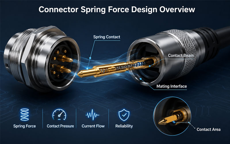
Connector Spring Force Design Overview


What Is Spring Force in Connector Contacts?

Spring force refers to the mechanical force generated by the elastic deformation of a connector contact element after mating.

When two contacts are connected:

1.The male and female contacts engage.

2.The contact element deforms elastically.

3.The spring force pushes the surfaces together.

4.Stable electrical contact is maintained.

This force creates the necessary contact pressure for reliable current transmission.

Common spring structures include:

  • Cantilever beams
  • Dual-beam contacts
  • Leaf springs
  • Cage-style contacts
  • Elastic socket structures

Each design provides different performance characteristics.


Why Spring Force Matters in Connector Reliability

The contact interface is constantly exposed to mechanical and environmental stress.

A properly designed spring force helps maintain performance under:

  • Vibration
  • Shock
  • Thermal expansion
  • Repeated mating cycles
  • Mechanical movement

Without sufficient spring force, connectors may experience:

  • Increased contact resistance
  • Signal interruption
  • Electrical arcing
  • Local heating
  • Premature failure

1.Spring Force Maintains Stable Electrical Contact

Electrical current flows through the actual contact points between mating surfaces.

The spring force determines how tightly these surfaces remain connected.

Proper contact pressure helps:

✔ Increase effective contact area

✔ Reduce resistance variation

✔ Improve current stability

✔ Prevent micro-movement


Low Spring Force Problems

Insufficient spring force can cause:

Contact Interruption

Small movements caused by vibration may temporarily break the electrical connection.

Increased Resistance

Poor contact pressure creates unstable electrical pathways.

Fretting Corrosion

Micro-motion between metal surfaces may generate wear particles and oxidation.


Excessive Spring Force Problems

Too much force can create:

High Insertion Force

Users may experience difficulty during mating.

Faster Contact Wear

Higher mechanical stress accelerates surface damage.

Reduced Mating Life

Repeated cycles may permanently deform the contact structure.


2.Spring Force and Contact Resistance Relationship

Contact resistance is directly affected by contact pressure.

Higher contact pressure generally improves electrical performance by creating more stable metal-to-metal contact.

However, the relationship is not unlimited.

After reaching an optimal range, increasing force provides fewer benefits while increasing mechanical stress.

Connector engineers must optimize:

Contact Force + Material Elasticity + Surface Condition

to achieve long-term reliability.


3.Contact Spring Design Affects Connector Durability

Different contact structures generate spring force in different ways.


Cantilever Beam Contacts

A cantilever beam uses a flexible metal arm to create contact pressure.

Advantages:

✔ Simple structure

✔ Cost-effective manufacturing

✔ Good electrical performance

Common applications:

  • PCB connectors
  • Automotive connectors
  • General electronic connectors

Dual Beam Contacts

Dual beam designs use two independent contact points.

Advantages:

✔ Improved redundancy

✔ Better vibration resistance

✔ More stable connection

If one contact point experiences contamination or wear, the second contact can help maintain electrical continuity.


Leaf Spring Contacts

Leaf spring structures provide controlled elastic force.

Advantages:

✔ Stable pressure distribution

✔ Good mechanical durability

✔ Suitable for high-cycle applications


4.Spring Force Helps Improve Vibration Resistance

Many connectors operate in environments with continuous vibration.

Examples:

  • Vehicles
  • Robots
  • Industrial machinery
  • Outdoor equipment

Vibration can cause:

  • Contact separation
  • Fretting wear
  • Signal interruption

Proper spring force helps maintain contact pressure during mechanical movement.

This is especially important for:

  • Automotive connectors
  • Circular connectors
  • Industrial Ethernet connectors

5.Spring Force Influences Mating Cycle Life

Every connector mating cycle creates mechanical stress.

During repeated mating:

  • Contact surfaces slide
  • Spring elements deform
  • Plating layers experience wear

A well-designed spring system maintains:

✔ Stable force over time

✔ Controlled contact wear

✔ Reliable electrical performance

For connectors requiring thousands of mating cycles, spring force consistency is critical.


6.Material Selection Determines Spring Performance

Spring force depends heavily on contact material properties.

Important factors include:

  • Elastic strength
  • Fatigue resistance
  • Conductivity
  • Corrosion resistance

Common contact materials include:

Copper Alloys

Advantages:

✔ Good conductivity

✔ Balanced mechanical performance


Phosphor Bronze

Advantages:

✔ Excellent spring properties

✔ Good fatigue resistance

Commonly used for:

  • High-cycle connectors
  • Signal connectors

Beryllium Copper

Advantages:

✔ High elasticity

✔ Excellent mechanical durability

Used in applications requiring:

  • High reliability
  • Long service life

7.Spring Force Must Be Combined with Contact Plating

Spring force alone cannot guarantee reliability.

The contact surface also requires proper plating.


Gold Plating

Benefits:

✔ Low contact resistance

✔ Excellent corrosion resistance

✔ Long mating life

Suitable for:

  • Signal connectors
  • Precision applications

Tin Plating

Benefits:

✔ Cost-effective

✔ Suitable for many power applications

Suitable for:

  • General electrical connectors

8.Testing Spring Force and Contact Reliability

Connector manufacturers validate spring performance through testing.

Common tests include:


Insertion and Extraction Force Testing

Measures:

  • Required mating force
  • User operation performance
  • Mechanical consistency

Contact Resistance Testing

Evaluates:

  • Electrical stability
  • Contact performance

Mating Cycle Testing

Verifies:

  • Contact durability
  • Spring performance after repeated use

Vibration Testing

Evaluates:

  • Contact stability under mechanical stress

9.Spring Force Design Requirements by Application

Different industries require different spring force characteristics.

Application Spring Force Requirements
Automotive Connector Vibration resistance, stable contact pressure
Robotics Connector High cycle durability, mechanical stability
Industrial Connector Reliable performance in harsh environments
Energy Storage Connector High current stability, thermal reliability
Medical Connector Stable connection and low failure risk

Common Spring Force Design Mistakes

Design Issue Potential Failure
Insufficient spring force Intermittent connection
Excessive spring force High insertion force
Poor material selection Loss of elasticity
Uneven pressure distribution Contact instability
Incorrect plating combination Increased resistance

How FPIC Optimizes Connector Contact Reliability

FPIC focuses on connector reliability through:

✔ Precision contact structure design

✔ Optimized spring force control

✔ Material and plating selection

✔ Contact resistance testing

✔ Mechanical reliability validation

Connector designs are evaluated to ensure:

  • Stable electrical performance
  • Reliable mating cycles
  • Consistent production quality

Through engineering optimization and manufacturing control, FPIC supports customers with reliable connector solutions for industrial and automotive applications.


Final Thoughts

Spring force is one of the most important elements in connector contact reliability.

A successful connector design requires the right balance between:

  • Contact pressure
  • Electrical performance
  • Mechanical durability
  • User operation

Too little force creates unstable connections.

Too much force reduces usability and service life.

The best connector designs achieve controlled spring force that maintains reliable performance throughout thousands of operating cycles.

A connector is not reliable because the contacts touch.

It is reliable because the contacts remain stable.


FAQ

What is spring force in a connector?

Spring force is the mechanical force generated by the elastic deformation of connector contacts after mating.

Why is spring force important for connector reliability?

It maintains contact pressure, reduces resistance variation, and improves resistance to vibration and mechanical stress.

Can higher spring force improve connector performance?

Not always. Excessive force can increase wear and reduce mating cycle life.

How is connector spring force tested?

Manufacturers evaluate spring performance through insertion force, extraction force, contact resistance, mating cycle, and vibration tests.

What materials are commonly used for connector spring contacts?

Copper alloys, phosphor bronze, and beryllium copper are commonly used due to their electrical and elastic properties.


Need Reliable Connector Contact Design?

FPIC provides custom connector solutions with expertise in contact structure design, spring force optimization, material selection, and reliability testing.

From prototype development to mass production, FPIC helps OEM customers create connectors designed for long-term performance.

Contact FPIC today to discuss your connector project.


Resources

1.IEC 60512 – Connectors for Electronic Equipment – Tests and Measurements
https://www.iec.ch/

Connector testing methods covering mechanical and electrical performance evaluation.

2.EIA-364 Connector Test Standards
https://www.eia-global.org/

Industry standards for connector reliability and performance testing.

3.USCAR Connector Performance Standards
https://www.uscar.org/

Automotive connector performance requirements and validation guidelines.
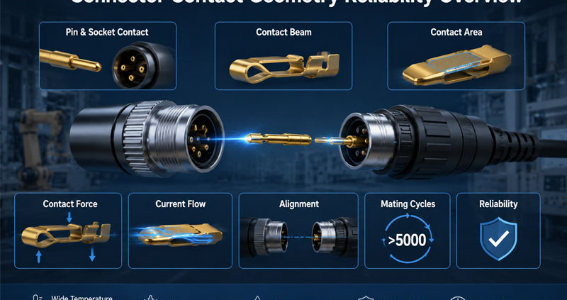
Connector Reliability Overview

A connector is only as reliable as its contact system.

Although the external housing provides protection and mechanical support, the actual electrical connection happens at the contact interface.

The design of this small area determines whether a connector can maintain stable performance under:

  • High current loads
  • Vibration
  • Temperature changes
  • Repeated mating cycles
  • Harsh operating environments

For applications such as automotive electronics, industrial automation, robotics, energy storage systems, and medical equipment, contact geometry plays a critical role in connector reliability.

A well-designed connector does not simply make contact.

It maintains consistent electrical and mechanical performance throughout its service life.

Connector Reliability Overview


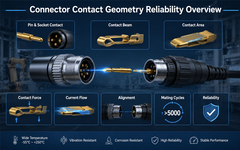
What Is Connector Contact Geometry?

Contact geometry refers to the physical design of the connector contact interface.

It includes:

  • Contact shape
  • Contact beam structure
  • Contact area
  • Contact engagement position
  • Contact pressure distribution
  • Wiping action during mating

The goal of contact geometry design is to achieve the right balance between:

  • Electrical conductivity
  • Mechanical strength
  • Contact stability
  • Mating durability

Different applications require different contact structures.

A high-current power connector and a high-speed signal connector may use completely different contact geometries because their performance requirements are different.


Why Contact Geometry Is Critical for Connector Reliability

When two connector contacts mate, several physical factors determine connection quality.

A reliable contact interface must provide:

Stable Electrical Path

Ensuring current can flow efficiently with minimal resistance.

Proper Contact Force

Maintaining connection stability without excessive mechanical stress.

Controlled Wear

Allowing repeated mating without rapid degradation.

Resistance to Environmental Stress

Maintaining performance against:

  • Vibration
  • Shock
  • Temperature variation
  • Corrosion

Poor contact geometry can result in:

  • Increased contact resistance
  • Intermittent electrical connection
  • Signal interruption
  • Excessive heat generation
  • Premature connector failure

1.Contact Shape Determines Connection Performance

The shape of the contact element directly affects current transmission and mechanical stability.

Common contact structures include:


Pin and Socket Contacts

Pin and socket designs are widely used in circular connectors and industrial connectors.

Advantages:

✔ Reliable alignment

✔ Stable contact interface

✔ Good environmental adaptability

The socket contact usually uses spring structures to maintain contact pressure around the pin.

This design helps compensate for:

  • Manufacturing tolerance
  • Vibration
  • Mechanical movement

Blade Contacts

Blade contacts provide a larger conductive path.

Advantages:

✔ High current capability

✔ Simple structure

✔ Good mechanical strength

They are commonly used in:

  • Power connectors
  • Automotive applications
  • Industrial equipment

Spring Contacts

Spring-based contacts use elastic deformation to maintain continuous pressure.

Advantages:

✔ Improved vibration resistance

✔ Stable contact force

✔ Longer service life

They are suitable for applications requiring frequent mating cycles.


2.Contact Force Affects Reliability and Mating Performance

Contact force is one of the most important design parameters.

The correct contact force ensures:

  • Stable electrical connection
  • Low contact resistance
  • Resistance to vibration

However, both insufficient and excessive force can create problems.


Too Low Contact Force

Potential issues:

  • Increased electrical resistance
  • Intermittent connection
  • Signal instability

Low contact force may allow micro-movement between contacts, causing electrical degradation over time.


Too High Contact Force

Potential issues:

  • Higher insertion force
  • Increased contact wear
  • Reduced mating cycles

A good connector design balances:

Contact Reliability + User Operation + Service Life


3.Contact Area Influences Current Flow and Heat Generation

The contact interface determines how efficiently electrical current transfers between mating components.

A well-designed contact area helps:

  • Reduce current concentration
  • Lower resistance
  • Minimize heat generation

However, contact area alone does not determine performance.

Engineers must also consider:

  • Contact pressure
  • Surface condition
  • Material properties
  • Contact alignment

A larger contact surface without proper pressure control may not provide better reliability.


4.Wiping Action Helps Maintain Clean Contact Surfaces

Many connector designs include wiping action during mating.

During insertion, the contact surfaces slide against each other.

This movement helps remove:

  • Dust particles
  • Surface oxidation
  • Minor contamination

Benefits include:

✔ Improved electrical stability

✔ Reduced contact resistance variation

✔ Better long-term reliability

Wiping action is especially important for:

  • Outdoor equipment
  • Industrial automation
  • High-cycle connectors

5.Contact Geometry Determines Mating Cycle Life

Every mating cycle creates mechanical stress on contacts.

Repeated connection and disconnection can cause:

  • Surface wear
  • Loss of contact force
  • Material deformation

A reliable contact design considers:

Contact Elasticity

Maintains pressure after repeated use.

Wear Resistance

Reduces surface damage.

Mechanical Stability

Prevents deformation during operation.

For connectors requiring thousands of mating cycles, optimized contact geometry is essential.


6.Alignment Design Prevents Contact Damage

Even a well-designed contact can fail if alignment is poor.

Incorrect alignment may cause:

  • Bent pins
  • Uneven contact pressure
  • Partial engagement
  • Contact damage

Reliable connector systems often include:

  • Polarization features
  • Guide structures
  • Mechanical keys
  • Alignment sleeves

These features ensure correct mating and protect the contact system.


7.Contact Geometry Influences Thermal Reliability

Electrical resistance generates heat.

When contact geometry is poor, current may concentrate in small areas, creating:

  • Hot spots
  • Temperature rise
  • Contact degradation

A properly designed contact structure improves:

  • Current distribution
  • Heat dissipation
  • Long-term stability

This is especially important for:

  • High-current connectors
  • Battery systems
  • Industrial power equipment

8.Contact Geometry Must Match Application Requirements

Different industries require different contact solutions.

Application Contact Design Priorities
Automotive Vibration resistance, durability, stable contact force
Robotics High mating cycles, mechanical stability
Industrial Automation Environmental protection, reliability
Energy Storage High current capability, thermal control
Medical Equipment Stable signal transmission, safety

Connector design should always begin with understanding the actual application environment.


9.Contact Material and Plating Work Together with Geometry

Contact geometry is only one part of connector reliability.

Material selection and surface treatment are equally important.


Contact Material

Common materials include:

  • Copper alloys
  • Brass
  • Phosphor bronze

Important characteristics:

  • Electrical conductivity
  • Spring performance
  • Mechanical strength

Contact Plating

Gold Plating

Advantages:

✔ Excellent corrosion resistance

✔ Low contact resistance

✔ Long mating life

Suitable for:

  • Signal connectors
  • Precision applications

Tin Plating

Advantages:

✔ Cost-effective

✔ Suitable for many power applications

Suitable for:

  • General electrical connections

10.How FPIC Optimizes Connector Contact Design

FPIC focuses on connector reliability through:

Precision Contact Engineering

Including:

  • Contact structure optimization
  • Contact force control
  • Mechanical tolerance management

Material and Plating Selection

Considering:

  • Current requirements
  • Environment
  • Mating cycles

Reliability Testing

Including:

  • Contact resistance testing
  • Insertion and extraction force testing
  • Mating cycle evaluation
  • Environmental testing

Through engineering optimization and manufacturing control, FPIC helps customers develop reliable connector solutions for demanding applications.


Common Contact Geometry Design Mistakes

Design Mistake Potential Result
Incorrect contact force Intermittent connection
Poor alignment design Contact damage
Insufficient contact area Heat generation
Weak wiping action Increased resistance
Improper material selection Reduced service life

Contact Geometry Design Checklist

Before finalizing a connector design, engineers should evaluate:

✔ Is the contact force within the correct range?

✔ Can the contact maintain stability after repeated mating?

✔ Is current distribution optimized?

✔ Does the geometry support the application environment?

✔ Are material and plating choices appropriate?

✔ Has the design been validated through testing?


Final Thoughts

Contact geometry is one of the most important factors influencing connector reliability.

A reliable connector requires careful optimization of:

  • Contact shape
  • Contact force
  • Contact area
  • Alignment
  • Material selection
  • Surface treatment

The contact interface may be small, but it determines the overall performance of the connector system.

A connector is not reliable because it connects once.

It is reliable because it maintains a stable connection thousands of times under real-world conditions.


FAQ

What is contact geometry in connectors?

Contact geometry refers to the physical structure and design of the electrical contact interface, including shape, contact area, and pressure distribution.

How does contact geometry affect connector reliability?

It affects electrical resistance, current flow, mating durability, vibration resistance, and long-term performance.

Why is contact force important in connector design?

Proper contact force ensures stable electrical connection while balancing insertion force and wear.

Can contact geometry affect connector temperature?

Yes. Poor contact geometry can increase resistance and create localized heat generation.

How do engineers improve connector contact reliability?

Engineers optimize contact structure, materials, plating, alignment, and validate performance through reliability testing.


Need a Reliable Custom Connector Solution?

FPIC provides custom connector design and manufacturing services with expertise in contact engineering, material selection, reliability testing, and mass production.

From concept development to final production, FPIC helps OEM customers build connectors designed for long-term performance.

Contact FPIC today to discuss your connector requirements.


Resources

  1. IEC 60512 – Connectors for Electronic Equipment – Tests and Measurements
    https://www.iec.ch/
    Connector testing methods covering electrical and mechanical performance evaluation.
  2. EIA-364 Connector Test Standards
    https://www.eia-global.org/
    Industry test standards for connector reliability and performance validation.
  3. IPC/WHMA-A-620 – Requirements and Acceptance for Cable and Wire Harness Assemblies
    https://www.ipc.org/
    Industry acceptance criteria for cable and wire harness assemblies.
Connector Design From Contact System to Final Assembly

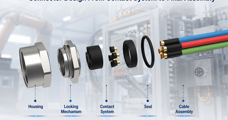
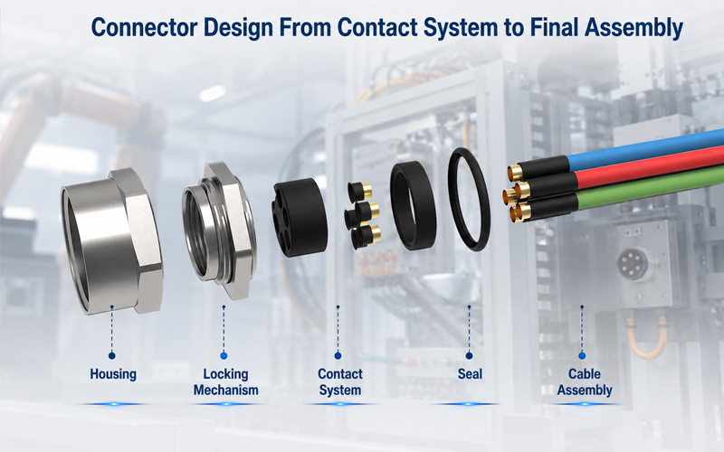
A connector may look like a simple component, but its performance depends on the interaction of multiple engineering elements.

A reliable connector requires careful design of:

  • Contact system
  • Housing structure
  • Locking mechanism
  • Sealing system
  • Material selection
  • Manufacturing process
  • Final assembly and testing

A mistake in any stage can affect:

  • Electrical performance
  • Mechanical reliability
  • Environmental protection
  • Service life

For engineers developing industrial, automotive, robotics, energy storage, and automation systems, connector design should be considered as a complete engineering process—not just a component selection task.

This guide explains the key stages of connector design, from the internal contact system to final production validation.

Connector Design From Contact System to Final Assembly


Why Connector Design Requires System-Level Thinking

A connector performs three primary functions:

Electrical Connection

Providing stable current or signal transmission.

Important factors:

Contact resistance

Current capacity

Signal integrity

Plating performance

Mechanical Connection

Maintaining a secure connection under real-world conditions.

Important factors:

Mating force

Locking structure

Vibration resistance

Mating cycles

Environmental Protection

Protecting internal components from harsh environments.

Important factors:

Waterproof sealing

Dust protection

Temperature resistance

Chemical exposure

A successful connector design balances all three requirements.


1.Contact System Design: The Core of Connector Performance

The contact system is the electrical heart of a connector.

Its design directly affects:

  • Conductivity
  • Heat generation
  • Reliability
  • Service life

Contact Geometry Design

Contact geometry determines how terminals connect and maintain contact force.

Key considerations include:

✔ Contact area

✔ Spring structure

✔ Contact pressure

✔ Current path design

A properly designed contact system provides:

Stable electrical connection

Low resistance

Long-term performance


Contact Material Selection

Common contact materials include:

Copper Alloys

Advantages:

✔ Good conductivity

✔ Balanced strength

✔ Cost efficiency

Phosphor Bronze

Advantages:

✔ Good spring performance

✔ Excellent fatigue resistance

Beryllium Copper

Advantages:

✔ High elasticity

✔ Excellent contact force retention

Used for:

  • High-cycle connectors
  • Precision applications

Contact Plating Selection

Surface plating affects:

  • Corrosion resistance
  • Contact stability
  • Mating life

Common options include:

Gold Plating

Advantages:

✔ Excellent corrosion resistance

✔ Reliable low contact resistance

Suitable for:

  • Signal connectors
  • Medical equipment
  • High-cycle applications

Tin Plating

Advantages:

✔ Cost-effective

✔ Suitable for many power applications

The correct plating depends on:

  • Current level
  • Environment
  • Required mating cycles

2.Housing Design: Mechanical Protection and Alignment

The connector housing protects internal contacts and ensures proper mating.

A good housing design must provide:

✔ Mechanical strength

✔ Accurate terminal positioning

✔ Electrical insulation

✔ Assembly efficiency


Housing Material Selection

Common materials include:

PA (Polyamide)

Used for:

  • Industrial connectors
  • General applications

Benefits:

  • Good strength
  • Cost efficiency

PBT

Benefits:

  • Dimensional stability
  • Low moisture absorption

PPS

Benefits:

  • High temperature resistance
  • Chemical resistance

Material selection depends on:

  • Operating temperature
  • Mechanical requirements
  • Environmental conditions

Terminal Positioning and Polarization

Connector housings should prevent incorrect assembly.

Important design features:

  • Keying structures
  • Polarization features
  • Secondary locks

These features help prevent:

❌ Wrong mating

❌ Terminal back-out

❌ Assembly mistakes


3.Locking Mechanism Design

A reliable locking system prevents accidental disconnection.

Common locking methods include:


Threaded Locking

Advantages:

✔ High vibration resistance

✔ Strong mechanical retention

Applications:

  • Industrial equipment
  • Outdoor systems

Push-Pull Locking

Advantages:

✔ Fast connection

✔ Easy operation

✔ High mating efficiency

Applications:

  • Medical
  • Automation
  • Test equipment

Snap Locking

Advantages:

✔ Simple operation

✔ Cost-effective

Applications:

  • General electronic applications

4.Sealing and Environmental Protection

For harsh environments, sealing design is critical.

Connector sealing protects against:

  • Water
  • Dust
  • Oil
  • Humidity

Common sealing components include:

  • O-rings
  • Gaskets
  • Rubber seals

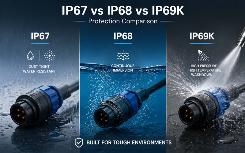
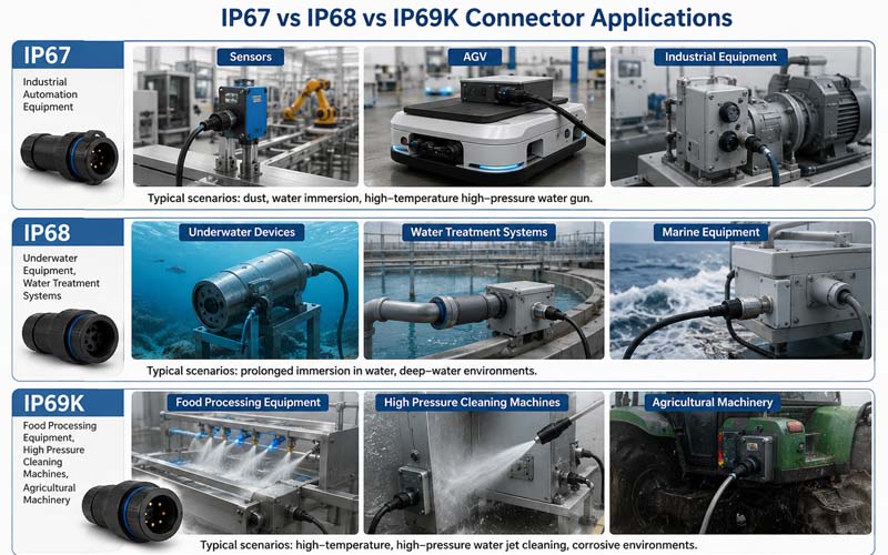
IP Protection Considerations

Depending on the application, connectors may require:

  • IP67
  • IP68
  • IP69K

Higher protection levels require careful control of:

  • Seal compression
  • Housing interface
  • Material compatibility

5.Connector Assembly Design

Connector assembly affects both quality and manufacturing efficiency.

A production-ready design should consider:


Terminal Insertion

Important factors:

✔ Insertion force

✔ Terminal retention

✔ Position accuracy


Secondary Locking System

Secondary locks improve:

  • Terminal retention
  • Assembly reliability
  • Safety

Assembly Error Prevention

Good designs include:

  • Visual identification
  • Mechanical keying
  • Assembly guidance

These features improve production consistency.


6.Connector Validation and Testing

Before mass production, connectors require validation.

Common tests include:


Electrical Testing

Including:

  • Contact resistance
  • Insulation resistance
  • Hi-Pot testing

Mechanical Testing

Including:

  • Insertion force
  • Extraction force
  • Mating cycles
  • Vibration testing

Environmental Testing

Including:

  • Temperature cycling
  • Humidity testing
  • Salt spray testing
  • Water ingress testing

Testing ensures the connector performs under real application conditions.


7.Connector Design for Mass Production

A successful connector design must also consider manufacturing.

Key DFM considerations include:

Injection Molding

Evaluate:

  • Wall thickness
  • Draft angle
  • Mold complexity

Terminal Stamping

Evaluate:

  • Material utilization
  • Contact geometry
  • Production consistency

Assembly Automation

Evaluate:

  • Assembly direction
  • Process repeatability
  • Inspection requirements

Good connector design reduces production risks.


How FPIC Approaches Connector Design

FPIC provides customized connector solutions from engineering design through mass production.

Our connector development process considers:

  • Contact system design
  • Housing structure
  • Material selection
  • Manufacturing feasibility
  • Assembly optimization
  • Reliability testing

By combining engineering experience with manufacturing capability, FPIC helps customers develop connectors that meet demanding industrial requirements.


Final Thoughts

Connector design is a system engineering process.

A reliable connector requires the right balance between:

  • Contact performance
  • Mechanical structure
  • Environmental protection
  • Manufacturing efficiency

From the first contact design to final assembly validation, every detail influences long-term reliability.

For OEM engineers, selecting the right connector partner means choosing a team that understands both product performance and manufacturing reality.

A high-quality connector is not simply assembled—it is engineered.


FAQ

What are the main parts of a connector?

The main parts include contacts, housing, locking mechanism, sealing components, and assembly features.

Why is contact design important in connectors?

The contact system determines electrical performance, contact resistance, current capability, and mating reliability.

What factors affect connector lifetime?

Key factors include materials, contact force, mating cycles, environment, vibration, and manufacturing quality.

What tests are required for connector validation?

Common tests include electrical testing, mechanical testing, environmental testing, and durability testing.

Why should connector design consider manufacturing early?

Early manufacturing consideration improves production efficiency, reduces defects, and controls cost.


Need a Custom Connector Solution?

FPIC develops customized connector solutions for industrial automation, robotics, energy storage, automotive, and other demanding applications.

From contact design and material selection to tooling, assembly, and testing, FPIC supports customers from concept development to mass production.

Contact FPIC today to discuss your connector project.


Resources

  1. IEC 60512 – Connectors for Electronic Equipment – Tests and Measurements
    https://www.iec.ch/
    Connector testing methods covering electrical, mechanical, and environmental performance.
  2. IPC/WHMA-A-620 – Requirements and Acceptance for Cable and Wire Harness Assemblies
    https://www.ipc.org/
    Industry requirements for cable assembly quality and workmanship.
  3. ISO 16750 – Road Vehicles Environmental Conditions and Testing
    https://www.iso.org/
    Environmental testing guidance for automotive electrical components.
  4. IATF 16949 Automotive Quality Management System
    https://www.iatfglobaloversight.org/
    Automotive quality management requirements for production consistency.
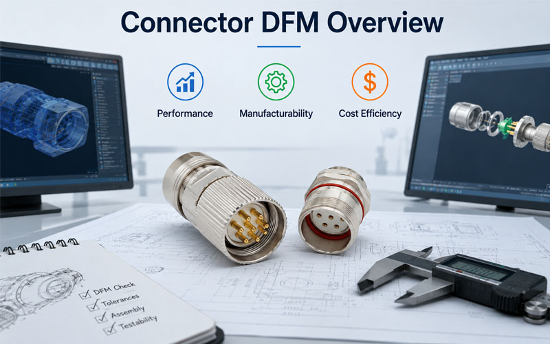
Connector DFM Design Optimization Overview

Designing a connector is not only about achieving the highest electrical performance.

A connector must also be:

  • Easy to manufacture
  • Consistent in mass production
  • Cost-effective
  • Reliable throughout its service life

Many connector designs fail to consider manufacturing requirements early enough.

The result can include:

  • Complex assembly processes
  • Higher tooling costs
  • Production delays
  • Difficult quality control
  • Increased unit cost

This is why Design for Manufacturing (DFM) plays an important role in connector development.

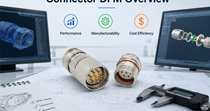
A successful connector design balances three key factors:

Performance + Manufacturability + Cost

Connector DFM Design Optimization Overview


What Is Connector DFM?

Connector DFM (Design for Manufacturing) is an engineering approach that considers production requirements during the design stage.

Instead of designing a connector first and solving manufacturing problems later, DFM integrates:

  • Material selection
  • Tooling requirements
  • Assembly processes
  • Testing methods
  • Production scalability

from the beginning.

The goal is to create a connector that performs well while remaining practical for high-volume manufacturing.


Why DFM Matters in Connector Development

A connector may perform well in a laboratory environment but face challenges during mass production.

Common issues caused by poor DFM include:

❌ Difficult assembly

❌ Tight manufacturing tolerances

❌ High tooling complexity

❌ Low production yield

❌ Increased inspection requirements

❌ Higher manufacturing cost

A DFM-focused design reduces these risks by considering the entire product lifecycle.


1.Design for Electrical Performance

The first priority of any connector is reliable electrical performance.

DFM does not mean reducing performance.

Instead, it means achieving required performance with an optimized design.

Key electrical considerations include:


Contact System Design

The contact structure affects:

  • Current capacity
  • Contact resistance
  • Mating cycles
  • Signal integrity

Engineers should evaluate:

✔ Contact geometry

✔ Contact force

✔ Material selection

✔ Plating thickness

✔ Current path design

A well-designed contact system improves reliability while avoiding unnecessary material costs.


Creepage and Clearance Design

For higher voltage applications, spacing requirements are critical.

Proper DFM considers:

  • Insulation distance
  • Housing structure
  • Manufacturing capability

Over-designing spacing may increase connector size and cost.

Under-designing may create safety risks.

The goal is the correct balance.


2.Design for Manufacturability

A connector designed for manufacturing should support stable and efficient production.

Important factors include:

Simplify Connector Structure

Complex structures increase:

  • Mold difficulty
  • Assembly steps
  • Failure risks

Good DFM practices include:

✔ Reducing unnecessary components

✔ Simplifying assembly direction

✔ Minimizing manual operations

✔ Improving part consistency


Optimize Housing Design

The connector housing must consider injection molding requirements.

Important factors:

  • Wall thickness
  • Draft angles
  • Rib design
  • Shrinkage control
  • Mold release

Poor housing design can lead to:

  • Warpage
  • Cracks
  • Dimensional variation

Improve Assembly Efficiency

Mass production requires repeatable assembly.

Design considerations:

✔ Easy terminal insertion

✔ Clear orientation features

✔ Locking mechanism feedback

✔ Error-proof assembly

These features reduce production errors and improve efficiency.


3.Material Selection for DFM

Material selection affects both performance and manufacturing cost.

Important factors include:

  • Temperature resistance
  • Mechanical strength
  • Chemical resistance
  • Processing requirements

Common connector materials:


Housing Materials

PA (Polyamide)

Advantages:

✔ Good mechanical strength

✔ Cost-effective

✔ Widely available

PBT

Advantages:

✔ Dimensional stability

✔ Good electrical insulation

PPS

Advantages:

✔ High temperature performance

✔ Excellent chemical resistance

The right material depends on the application requirements.


Contact Materials

Common choices:

  • Copper alloys
  • Phosphor bronze
  • Beryllium copper

Selection depends on:

  • Conductivity
  • Spring performance
  • Mating cycles
  • Cost targets

4.Design for Tooling Efficiency

Connector tooling can represent a significant development investment.

DFM helps reduce tooling complexity.

Key considerations:

Mold Design

Good connector designs consider:

✔ Fewer sliders

✔ Simple parting lines

✔ Stable cavity design

✔ Easy maintenance


Terminal Stamping Design

Terminal design affects:

  • Material usage
  • Stamping speed
  • Production consistency

Optimized terminal geometry can reduce:

  • Material waste
  • Processing cost
  • Defect rates

5.Balancing Performance and Cost

The lowest-cost connector is not always the most economical solution.

A cheaper connector may create:

  • Higher failure risk
  • More maintenance
  • Increased warranty costs

Effective cost optimization focuses on:

Right Specification

Avoid unnecessary features.

Example:

Not every application requires:

  • Premium plating
  • Extreme temperature materials
  • Maximum mating cycles

Production Efficiency

Reduce cost through:

✔ Better tooling design

✔ Automated assembly

✔ Higher yield

✔ Reduced inspection time


Lifecycle Cost

A reliable connector can reduce:

  • Downtime
  • Replacement costs
  • Field failures

The best design optimizes total value, not only unit price.


6.DFM Review Process for Connector Development

A typical connector DFM review includes:

Step 1: Requirement Analysis

Evaluate:

  • Electrical requirements
  • Mechanical conditions
  • Environmental exposure
  • Cost targets

Step 2: Design Review

Check:

  • Structure
  • Materials
  • Tolerances
  • Assembly method

Step 3: Manufacturing Evaluation

Review:

  • Mold feasibility
  • Stamping process
  • Automation possibility
  • Testing requirements

Step 4: Prototype Validation

Perform:

  • Dimensional inspection
  • Electrical testing
  • Mechanical testing
  • Environmental testing

Step 5: Mass Production Optimization

Monitor:

  • Yield
  • Process stability
  • Quality data
  • Cost performance

How FPIC Applies DFM Principles to Connector Development

FPIC supports customers from connector concept development to mass production.

Our engineering approach considers:

  • Application requirements
  • Connector structure
  • Material selection
  • Tooling feasibility
  • Assembly efficiency
  • Quality validation

Through DFM-driven development, FPIC helps customers achieve connectors that are:

✔ Reliable

✔ Manufacturable

✔ Cost-efficient

✔ Ready for mass production


Final Thoughts

A successful connector design requires more than excellent technical specifications.

The best connector balances:

  • Electrical performance
  • Mechanical reliability
  • Manufacturing efficiency
  • Cost control

By applying DFM principles early, engineers can reduce development risks, improve production consistency, and create products that perform reliably in real-world applications.

Good connector design begins before production starts.


FAQ

What does DFM mean in connector design?

DFM means Design for Manufacturing, an approach that optimizes connector design for efficient and reliable production.

Why is DFM important for connectors?

DFM reduces manufacturing problems, improves production yield, lowers cost, and helps ensure consistent quality.

Does DFM reduce connector performance?

No. Proper DFM achieves the required performance while improving manufacturability and cost efficiency.

What factors should be considered during connector DFM?

Engineers should consider materials, tooling, assembly process, tolerances, testing, and production requirements.

When should DFM review happen?

DFM should begin during the early connector design stage before tooling and mass production.


Need a Connector Designed for Mass Production?

FPIC provides customized connector solutions with engineering support from design optimization to volume manufacturing.

With experience in connector development, tooling coordination, assembly, and testing, FPIC helps OEM customers create reliable and production-ready connector solutions.

Contact FPIC today to discuss your connector development project.


Resources

  1. IEC 60512 – Connectors for Electronic Equipment – Tests and Measurements
    https://www.iec.ch/
    Connector testing methods for electrical and mechanical performance evaluation.
  2. IPC/WHMA-A-620 – Requirements and Acceptance for Cable and Wire Harness Assemblies
    https://www.ipc.org/
    Industry requirements for cable and harness manufacturing quality.
  3. ISO 9001 Quality Management Systems
    https://www.iso.org/iso-9001-quality-management.html
    Quality management principles supporting consistent manufacturing processes.
  4. IATF 16949 Automotive Quality Management System
    https://www.iatfglobaloversight.org/
    Automotive quality requirements focused on process control and defect prevention.
How Temperature Rise Affects High-Current Connectors

High-current connector selection often starts with one number: the rated current.

A customer may see “450A” on a product specification and reasonably assume that the connector can continuously carry 450A in any equipment environment.

That assumption can be dangerous.

Quick Answer:

Temperature rise in a high-current connector depends on current, contact resistance, conductor size, terminal design, material, ambient temperature, installation conditions, and heat dissipation. A 450A rating only applies under defined test conditions; actual continuous current may need to be reduced when ambient temperature or thermal loading increases.

That is why high-current connector engineering should focus not only on current rating, but also on thermal performance under real operating conditions.


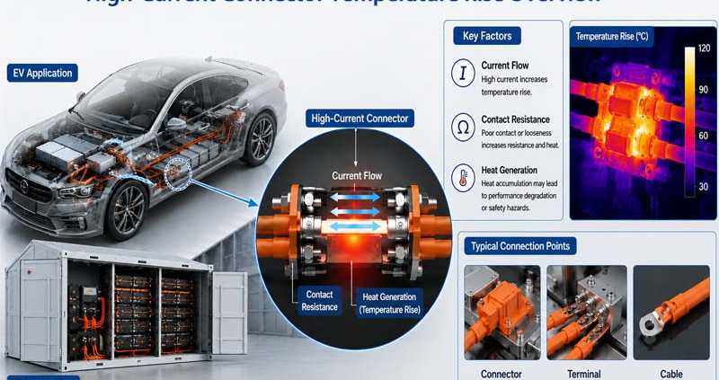
Why High-Current Connectors Generate Heat

Every electrical connection has resistance.

Even when that resistance is very small, current passing through the interface generates heat.

The basic relationship is:

Power loss = I² × R

This is one of the most important relationships in high-current connector design.

If current doubles while resistance remains unchanged, the heat generated by resistive losses increases by a factor of four.

That means a resistance change that seems insignificant at 10A may become important at 300A or 450A.

For example, heat can develop at:

  • contact interfaces;
  • crimp connections;
  • busbar interfaces;
  • conductor transitions;
  • cable terminals;
  • bolted connections.

The goal is therefore not simply to achieve low resistance at the initial test.

The contact system must maintain low and stable resistance throughout its service life.


Contact Resistance Is One of the Main Heat Sources

Contact resistance is created where two conductive surfaces touch.

In a high-current connector, this usually occurs between the plug and receptacle terminals.

The resistance depends on several factors:

  • contact geometry;
  • effective contact area;
  • normal contact force;
  • surface roughness;
  • terminal material;
  • plating material;
  • contamination;
  • wear;
  • corrosion;
  • mating cycles.

A well-designed terminal provides sufficient contact pressure to maintain a stable conductive path.

If contact pressure becomes too low, resistance may rise.

This can lead to:

Higher resistance → More heat → Faster material degradation → Even higher resistance

That cycle can become a long-term reliability risk.

TE describes low contact resistance as one reason its high-power connector designs can reduce temperature rise and power loss. Molex similarly links low contact resistance with lower voltage drop and lower heat generation in its high-current COEUR-based interconnects.


Terminal Material Influences Thermal Performance

How Temperature Rise Affects High-Current Connectors

Terminal material must provide both electrical conductivity and mechanical stability.

Typical high-current connector contacts use copper or copper-alloy materials.

Pure copper offers excellent conductivity, but connector terminals also require mechanical properties such as:

  • strength;
  • spring stability;
  • formability;
  • fatigue resistance;
  • resistance to stress relaxation.

Depending on the terminal structure, manufacturers may therefore use different copper alloys to balance conductivity and mechanical performance.

Common options include:

  • high-conductivity copper;
  • brass;
  • phosphor bronze;
  • copper-nickel-silicon alloys;
  • other high-conductivity copper alloys.

FPIC’s internal connector materials identify alloys such as C7025, C7035, and C18400 as suitable options for higher-current applications because they provide a useful combination of conductivity and mechanical properties.

Material choice should therefore be based on both electrical and mechanical requirements.


Plating Also Affects Contact Stability

The base terminal material is only one part of the contact system.

The contact surface may use plating such as:

  • tin;
  • silver;
  • gold;
  • nickel underlayers.

For high-current power applications, silver plating is commonly used because of its conductivity and contact performance.

Tin can also be suitable in many applications, although friction, fretting, oxidation, temperature, and mating-cycle requirements must be considered.

The plating system affects:

  • contact resistance;
  • corrosion resistance;
  • wear;
  • friction;
  • temperature stability;
  • service life.

The correct plating is therefore determined by the application rather than by choosing the most expensive material.


Cable Cross-Section Directly Affects Temperature Rise

A connector cannot be evaluated independently from its cable.

The resistance of a conductor depends on:

Material resistivity × conductor length ÷ conductor cross-sectional area

In practical terms:

A smaller conductor generally has greater resistance and produces more heat under the same current.

This is why connector specifications normally define compatible cable sizes.

For example, a high-current interface might be designed around conductor sizes such as:

  • 35 mm²;
  • 50 mm²;
  • 70 mm²;
  • 95 mm²;
  • 120 mm²;
  • 150 mm².

The cable cross-section must match both:

  1. the required current capacity; and
  2. the terminal crimp or termination design.

Phoenix Contact provides a useful example: the same connector can have different permissible currents depending on whether it is used with 2.5 mm², 4 mm², or 6 mm² conductors. Its published derating example shows that conductor size and ambient temperature both materially change the usable current.


Crimp Quality Can Become a Hidden Heat Source

Even when the connector and cable are correctly sized, poor termination can create additional resistance.

For a crimped connection, engineers must control:

  • crimp height;
  • crimp width;
  • conductor position;
  • conductor compression;
  • strand damage;
  • bellmouth;
  • terminal deformation;
  • pull-out force.

A poor crimp can create:

  • insufficient conductor contact;
  • uneven current distribution;
  • localized resistance;
  • localized heating.

FPIC’s terminal crimping standards therefore treat crimp height as one of the most important production controls and also use pull-force and cross-section analysis to verify termination quality.

For high-current connectors, termination quality is part of thermal management.


Ambient Temperature Changes the Available Thermal Margin

Connector temperature is not determined by self-heating alone.

The final operating temperature is approximately influenced by:

Ambient temperature + temperature rise caused by current

This means the same connector may behave differently in:

  • a 25°C laboratory;
  • a 40°C industrial cabinet;
  • a 55°C BESS cabinet;
  • an outdoor enclosure exposed to solar heating.

If a connector housing or cable insulation has a maximum permitted operating temperature, higher ambient temperature leaves less room for self-heating.

Phoenix Contact describes current-carrying capacity as dependent on both self-heating and ambient temperature, and its derating curves show permissible current decreasing as ambient temperature rises.

This is why high-current connector selection should include a current-temperature derating curve, not only one headline ampere value.


Continuous Current Is More Important Than Short Peak Current

A connector may experience several types of current:

  • continuous operating current;
  • short peak current;
  • startup current;
  • overload current;
  • pulse current.

These loads do not create the same thermal effect.

A short-duration peak may not allow enough time for the complete connector assembly to reach thermal equilibrium.

Continuous current is different.

When current flows for a long period, the connector continues heating until the generated heat and dissipated heat reach equilibrium.

For BESS applications, this distinction is particularly important because energy storage systems can operate under sustained charging or discharging conditions.

Therefore, the engineering question should not only be:

What is the maximum current?

It should also be:

How long will that current flow?


Why “Rated 450A” Does Not Mean 450A Everywhere

This is the most important point of the article.

A current rating is normally determined under specified test conditions.

Those conditions can include:

  • ambient temperature;
  • conductor size;
  • conductor length;
  • contact configuration;
  • mounting arrangement;
  • temperature-rise limit;
  • airflow;
  • measurement location.

TE explicitly states that its published current ratings represent maximum continuous current under defined or optimum conditions and that derating factors must be applied for higher ambient temperature and multiple loaded circuits.

IEC 60512-5-1 defines a standardized method for evaluating connector temperature rise under current load, while IEC 60512-5-2 addresses current-temperature derating at elevated ambient temperatures.

Therefore:

450A means:

The connector has demonstrated a defined current-carrying capability under specified conditions.

It does not mean:

The connector can operate continuously at 450A in every enclosure, cable configuration, temperature, altitude, or cooling condition.

That distinction should always be explained clearly to customers.


Multiple Loaded Contacts Can Change Current Capacity

For multi-contact connectors, another factor appears: mutual heating.

When multiple adjacent contacts carry current simultaneously, each contact contributes heat to the connector housing.

This raises the internal temperature and can reduce the current that each contact can safely carry.

TE notes that the current capacity per contact decreases when multiple contacts are simultaneously used for power transmission.

This means engineers must define:

  • how many contacts carry current;
  • current per contact;
  • spacing between contacts;
  • conductor sizes;
  • enclosure temperature.

A single-contact rating cannot simply be multiplied by the number of contacts.


Connector Housing Material Sets Another Thermal Limit

The terminal is not the only component exposed to heat.

The housing, seals, cable insulation, and nearby materials also have temperature limits.

Typical connector housing materials include:

  • PA66;
  • PBT;
  • LCP;
  • PA6T;
  • PA9T;
  • PPS.

Different polymers provide different:

  • heat resistance;
  • mechanical strength;
  • moisture absorption;
  • dimensional stability;
  • flame performance.

FPIC’s internal engineering materials identify high-temperature materials such as LCP, PA9T, PA6T, PA46, and PPS for connector designs that must withstand elevated-temperature processes such as reflow soldering.

The thermal limit of the complete system should therefore reflect the lowest critical material limit, not only the copper contact.


High-Voltage BESS Cabinets Create More Difficult Thermal Conditions

Energy storage systems are a particularly relevant example.

Inside a BESS cabinet, multiple heat sources may exist:

  • battery modules;
  • busbars;
  • contactors;
  • fuses;
  • high-current connectors;
  • power conversion equipment;
  • cable bundles.

The cabinet itself may also have restricted airflow.

This means the connector operates within a larger thermal system.

Engineers must consider:

  • cabinet ambient temperature;
  • cable bundle temperature;
  • neighboring components;
  • ventilation;
  • cooling system design;
  • continuous charge/discharge profile.

For this reason, the connector temperature should ideally be evaluated inside a representative system environment rather than only through a catalog value.


Temperature Rise Testing Provides the Evidence

Temperature-rise testing helps determine how much the connector heats when current passes through it.

A typical test process includes:

  1. assemble the connector with the specified conductor;
  2. place temperature sensors at defined measurement points;
  3. record initial ambient and component temperature;
  4. apply the test current;
  5. wait until thermal equilibrium;
  6. record the maximum temperature;
  7. calculate the temperature rise;
  8. repeat at different current levels if required.

IEC 60512-5-1 specifically defines a test method for assessing current-carrying capability based on connector temperature rise.

The resulting data can then help generate a current-temperature derating curve.


What FPIC Tests During High-Current Validation

FPIC has dedicated equipment for connector electrical and thermal validation.

Our internal laboratory capability includes:

  • temperature-rise testers;
  • contact-impedance testers;
  • withstand-voltage testers;
  • insulation-resistance testing;
  • insertion and extraction force testing;
  • vibration testing;
  • thermal-shock chambers;
  • X-ray inspection;
  • dimensional inspection.

FPIC’s equipment list includes multiple temperature-rise testers and contact-impedance instruments, supporting validation of high-current connector and cable-assembly performance.

For high-current projects, the validation plan can evaluate:

  • connector temperature rise;
  • terminal resistance;
  • cable temperature;
  • crimp condition;
  • interface stability;
  • mechanical reliability.

Applying This to FPIC’s 2000V 450A Connector

FPIC’s high-current energy storage connector portfolio includes 2000V / 450A solutions for battery-system applications.

But the correct engineering message is not:

“450A can always be used continuously.”

The more technically credible message is:

The 450A platform is designed and validated for high-current energy storage applications under defined conditions, and final current capability should be confirmed against conductor size, ambient temperature, installation environment, and system thermal requirements.

This distinction strengthens rather than weakens the product story.

It tells engineers that FPIC understands how current ratings actually work.

For BESS customers, FPIC can support project evaluation based on:

  • system voltage;
  • continuous and peak current;
  • cable cross-section;
  • connector mounting;
  • ambient temperature;
  • cabinet cooling;
  • duty cycle;
  • required temperature-rise limit.

This moves the discussion from catalog selling to engineering selection support.


High-Current Connector and Cable Assembly Must Be Evaluated Together

For high-current systems, the connector and cable assembly form one electrical and thermal path.

The evaluation should include:

Component Key thermal factors
Contact Material, geometry, resistance, plating
Terminal Crimp structure and conductor interface
Cable Cross-section, material, length, insulation
Connector housing Temperature capability and heat dissipation
Busbar interface Surface area, contact pressure, resistance
Cabinet Ambient temperature and airflow
Load Continuous current, peak current, duty cycle

Ignoring any one of these factors can produce an incomplete thermal assessment.


A Practical High-Current Connector Selection Checklist

Before selecting a high-current connector, provide the following data:

Electrical Requirements

  • nominal voltage;
  • maximum voltage;
  • continuous current;
  • peak current;
  • peak duration;
  • duty cycle.

Cable Requirements

  • conductor material;
  • conductor cross-section;
  • cable outer diameter;
  • insulation temperature rating.

Thermal Environment

  • minimum and maximum ambient temperature;
  • enclosure temperature;
  • airflow;
  • cooling method;
  • nearby heat sources.

Mechanical Installation

  • panel mount or cable mount;
  • busbar connection;
  • cable orientation;
  • available space.

Validation Requirements

  • permitted temperature rise;
  • test current;
  • test duration;
  • applicable IEC, UL, or customer standards.

Providing this information allows engineers to evaluate the real usable current, not simply repeat the catalog rating.


Frequently Asked Questions

1. What causes temperature rise in a connector?

Temperature rise primarily comes from electrical resistance in contacts, terminals, crimps, conductors, and interfaces while current is flowing.

2. Does lower contact resistance reduce temperature rise?

Generally yes. Lower resistance reduces resistive power loss at a given current, assuming the rest of the thermal system remains unchanged.

3. Does a larger cable always reduce connector temperature?

A larger conductor usually reduces cable resistance and can improve heat conduction away from the interface, but connector geometry, terminal design, ambient temperature, and installation conditions must still be evaluated.

4. Can a 450A connector continuously carry 450A?

Only under the conditions for which the current rating has been established. Higher ambient temperature, different conductor sizes, restricted cooling, or other installation factors may require derating.

5. Why is temperature-rise testing important?

It verifies how the complete connector assembly behaves under current load and helps determine whether the contact, terminal, housing, and cable remain within permitted temperature limits.

6. What is a connector derating curve?

A derating curve shows how permissible current decreases as ambient temperature increases. It provides a more realistic selection tool than a single rated-current number.


Conclusion

Current rating alone does not define high-current connector performance.

Temperature rise depends on the complete electrical and thermal system:

current + resistance + conductor + material + ambient temperature + installation + duty cycle

For BESS and other high-power systems, this is why a 450A connector should be evaluated as part of the complete application rather than treated as an isolated 450A component.

FPIC supports high-current connector and cable-assembly projects with connector development, conductor and terminal matching, temperature-rise testing, contact-resistance measurement, prototype validation, and repeat-production quality control.

Discuss Your High-Current Connector Project

FPIC supports high-voltage and high-current interconnection development for BESS, battery systems, industrial equipment, and customized power applications.

Send us your voltage, current profile, cable specification, ambient temperature, installation method, and project drawings for engineering evaluation.

Email: info@fpiconn.com


Resources

  1. IEC. IEC 60512-5-1:2002 – Connectors for Electronic Equipment – Current-Carrying Capacity Tests – Temperature Rise.
  2. IEC. IEC 60512-5-2:2002 – Connectors for Electronic Equipment – Current-Temperature Derating.
  3. TE Connectivity. Battery Pack Connectors – Current Carrying Capacity, T-Rise and Derating.
  4. TE Connectivity. Power Connectivity – Current Rating and Derating Guidance.
  5. Phoenix Contact. Electrical Tests for Connectors – Current Carrying Capacity and Derating.
  6. Molex. SW1 High-Current Interconnects and COEUR Socket Technology.
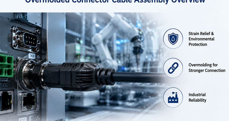
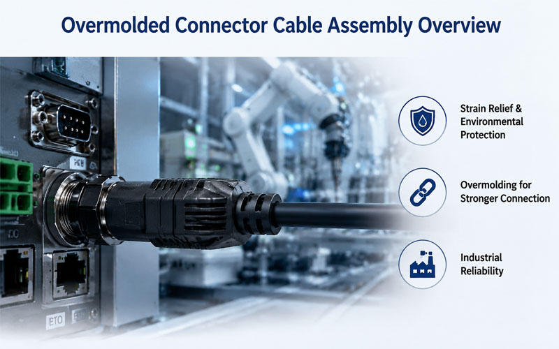
Overmolded Connector Cable Assembly Overview

Connector cable assemblies are widely used in industrial automation, robotics, medical equipment, transportation, energy systems, and outdoor applications where reliability is critical.

While connector selection and cable specifications are important, the connection between the cable and connector is often the weakest point in a system. Repeated bending, vibration, moisture exposure, and mechanical stress can gradually damage this area and lead to electrical failures.

Overmolding technology provides an effective solution by creating a strong, integrated protective structure around the connector and cable transition area.

By improving sealing, strain relief, and mechanical protection, overmolding helps extend service life and improve the reliability of cable assemblies in demanding environments.

Overmolded Connector Cable Assembly Overview


What Is Overmolding in Connector Cable Assemblies?

Overmolding is a manufacturing process where a protective material is molded directly around a connector, cable exit, or existing assembly component.

During the process:

1.The connector and cable are positioned inside a mold.

2.A thermoplastic or elastomer material is injected around the assembly.

3.The material forms a permanent protective layer.

4.The finished assembly becomes a single integrated component.

Unlike traditional methods that rely only on external boots or mechanical clamps, overmolding creates a seamless connection between the connector and cable.


Why Connector Cable Assemblies Need Overmolding

The cable exit area experiences some of the highest mechanical stress in an assembly.

Common failure causes include:

  • Repeated bending
  • Pulling force
  • Vibration
  • Moisture penetration
  • Cable twisting
  • Connector loosening

Without proper protection, these stresses can cause:

  • Broken conductors
  • Damaged insulation
  • Seal failure
  • Intermittent electrical connections
  • Reduced service life

Overmolding strengthens this critical transition area and improves overall assembly durability.


1.Improved Strain Relief and Mechanical Protection

One of the biggest advantages of overmolding is enhanced strain relief.

During operation, cables may experience:

  • Pulling force
  • Bending cycles
  • Repeated movement
  • Installation stress

A properly designed overmold distributes mechanical stress over a larger area instead of concentrating it at the cable exit.

Benefits include:

✔ Reduced cable fatigue

✔ Improved bend resistance

✔ Better pull-force performance

✔ Longer cable life

For applications such as robotics, servo systems, and moving machinery, effective strain relief is essential.


2.Enhanced Waterproof and Environmental Protection

Many industrial applications require protection against moisture, dust, chemicals, and harsh environments.

Overmolding creates a sealed structure that reduces the risk of:

  • Water ingress
  • Dust contamination
  • Corrosion
  • Chemical exposure

Depending on design and material selection, overmolded cable assemblies can support demanding protection requirements such as IP-rated applications.

Typical applications include:

  • Outdoor equipment
  • Industrial sensors
  • Automation systems
  • Medical devices
  • Transportation equipment

3.Increased Vibration and Shock Resistance

Industrial environments often expose connectors to continuous vibration and mechanical impact.

Examples include:

  • Robotics
  • CNC equipment
  • Construction machinery
  • Vehicle systems

Overmolding helps secure the connector-to-cable interface by:

  • Reducing connector movement
  • Supporting cable orientation
  • Absorbing mechanical stress
  • Preventing loosening

This improves reliability in applications where equipment operates continuously.


4.Better Protection Against Contamination

Traditional connector assemblies may have gaps where dust, oil, or moisture can accumulate.

Overmolding creates a smooth external surface that helps prevent contamination buildup.

Advantages include:

  • Easier cleaning
  • Improved hygiene
  • Reduced corrosion risk
  • Better long-term stability

This is especially valuable in:

  • Medical equipment
  • Food processing systems
  • Laboratory instruments

5.Improved Cable Assembly Durability During Installation

Cable assemblies are often exposed to handling stress before installation.

Overmolding protects critical areas during:

  • Transportation
  • Installation
  • Maintenance
  • Equipment replacement

A robust molded structure reduces accidental damage and improves field reliability.


Material Selection Matters in Overmolding

The performance of an overmolded cable assembly depends heavily on material selection.

Common materials include:

PVC

Advantages:

  • Cost-effective
  • Good flexibility
  • Suitable for general industrial applications

TPU

Advantages:

  • Excellent abrasion resistance
  • High flexibility
  • Good mechanical strength

Common applications:

  • Robotics
  • Motion systems
  • Industrial automation

Silicone

Advantages:

  • Wide temperature range
  • Excellent flexibility
  • Medical compatibility

Common applications:

  • Medical equipment
  • High-temperature environments

Choosing the correct material depends on:

  • Temperature requirements
  • Chemical exposure
  • Flexing cycles
  • Environmental conditions

Overmolding Design Considerations

A successful overmolded cable assembly requires careful engineering.

Important considerations include:

Cable Exit Design

The transition area must provide:

  • Smooth stress distribution
  • Proper bending support
  • Adequate sealing

Material Compatibility

The overmold material must bond properly with:

  • Cable jacket
  • Connector housing
  • Sealing components

Application Requirements

Engineers should evaluate:

  • Static or dynamic movement
  • Operating temperature
  • IP protection requirements
  • Mechanical loads
  • Expected service life

How FPIC Provides Overmolded Connector Cable Assembly Solutions

FPIC provides customized connector cable assemblies with overmolding capabilities for industrial, medical, automation, and harsh-environment applications.

Our manufacturing capabilities include:

  • Custom connector integration
  • Cable assembly production
  • Overmolding solutions
  • Electrical testing
  • High-volume manufacturing

By combining engineering design with controlled manufacturing processes, FPIC helps customers achieve reliable cable assemblies with improved mechanical protection and long-term performance.


Final Thoughts

Overmolding is more than an appearance improvement—it is a reliability enhancement technology.

By strengthening the connector-to-cable transition area, improving sealing, and reducing mechanical stress, overmolding helps cable assemblies perform reliably in challenging environments.

For OEM customers, selecting the right overmolded connector cable assembly can reduce maintenance costs, minimize failures, and extend equipment service life.

A reliable connection starts with protecting the weakest point.


FAQ

What is overmolding in cable assemblies?

Overmolding is a process where protective material is molded around a connector and cable interface to create an integrated, durable assembly.

Why is overmolding important for connector cables?

It improves strain relief, sealing, vibration resistance, and mechanical protection, helping extend cable assembly life.

Are overmolded cable assemblies waterproof?

Properly designed overmolded assemblies can provide enhanced environmental protection and support IP-rated applications.

Which materials are commonly used for cable overmolding?

Common materials include PVC, TPU, and silicone, depending on flexibility, temperature, and environmental requirements.

What applications use overmolded cable assemblies?

They are widely used in robotics, industrial automation, medical equipment, outdoor systems, transportation, and energy applications.


Need Custom Overmolded Connector Cable Assemblies?

FPIC specializes in customized connector cable assemblies with overmolding solutions for demanding industrial applications.

From connector selection and cable design to molding, testing, and mass production, FPIC provides reliable interconnection solutions designed for long-term performance.

Contact FPIC today to discuss your custom cable assembly requirements.


Resources

  1. IPC/WHMA-A-620 – Requirements and Acceptance for Cable and Wire Harness Assemblies
    https://www.ipc.org/
    Industry standard covering workmanship, inspection, and acceptance requirements for cable and wire harness assemblies.
  2. IEC 60529 – Degrees of Protection Provided by Enclosures (IP Code)
    https://www.iec.ch/
    Defines protection levels against dust and water ingress for electrical equipment.
  3. UL Solutions – Cable and Wire Safety Resources
    https://www.ul.com/
    Provides technical information related to cable safety, materials, and performance requirements.
  4. ISO 10993 – Biological Evaluation of Medical Devices
    https://www.iso.org/standard/68936.html
    Provides evaluation guidance for materials used in medical applications.
  5. WHMA – Wire Harness Manufacturer’s Association
    https://www.whma.org/
    Provides industry resources and best practices for cable assembly and harness manufacturing.
Common Shield Termination Mistakes

As industrial automation systems continue to adopt high-speed communication protocols such as Industrial Ethernet, EtherCAT, PROFINET, and CAN Bus, electromagnetic compatibility (EMC) has become an essential part of circular connector design.

While engineers often focus on cable shielding, one critical detail is frequently overlooked—the shield termination inside the connector.

A high-quality shielded cable can still perform poorly if the shield is improperly terminated. In many EMC failures, the connector itself is not the problem; rather, it is the way the shield is connected.

This article explains the most common shield termination mistakes found in circular connectors and provides practical recommendations for improving EMC performance.

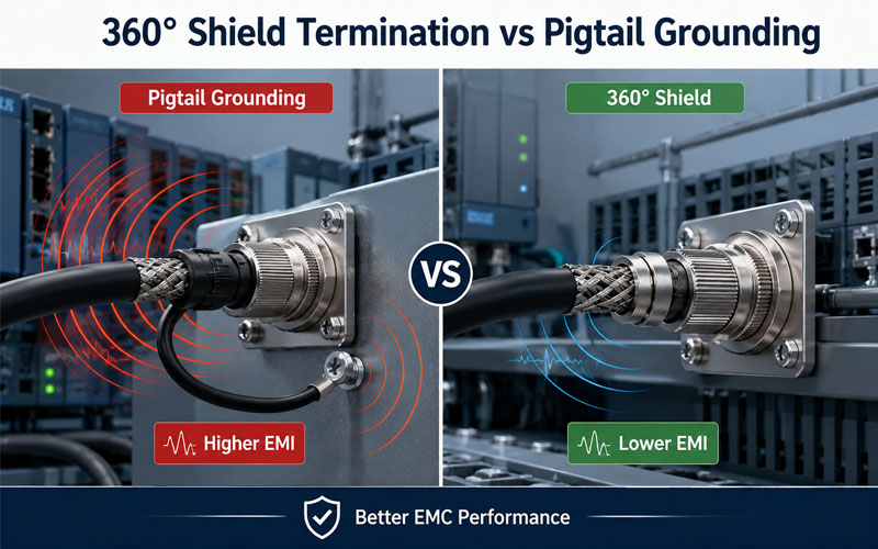
360° Shield Termination vs Pigtail Grounding


What Is Shield Termination?

Shield termination refers to the method used to electrically connect the cable shield to the connector housing or grounding system.

Its purpose is to:

  • Maintain shield continuity
  • Minimize electromagnetic emissions
  • Improve immunity against external interference
  • Provide a low-impedance path for high-frequency noise

A properly terminated shield allows electromagnetic energy to flow safely to ground instead of coupling into nearby signal conductors.


Why Shield Termination Matters

Modern industrial equipment contains numerous EMI sources, including:

  • Servo drives
  • Frequency inverters
  • Switching power supplies
  • Industrial Ethernet
  • High-speed digital communication
  • High-current power cables

Without effective shield termination, these noise sources may result in:

  • Communication failures
  • Packet loss
  • Encoder errors
  • Sensor instability
  • Unexpected equipment shutdown

Proper shield termination is often the difference between passing and failing EMC testing.


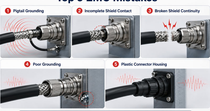
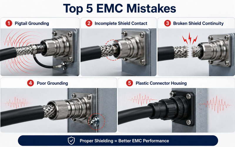
Common Mistake #1: Pigtail Grounding

One of the most common installation mistakes is connecting the shield through a long drain wire or “pigtail.”

Although convenient, this creates additional inductance that significantly reduces shielding effectiveness at high frequencies.

Recommended practice:

  • Avoid long pigtails.
  • Use direct 360° shield termination whenever possible.

Common Mistake #2: Incomplete 360° Shield Contact

Some connectors only contact a small portion of the cable braid.

This creates gaps in the shielding path and allows electromagnetic energy to leak.

Good shield termination should provide:

  • Full circumferential contact
  • Uniform pressure
  • Continuous metal-to-metal connection

Complete 360° termination offers substantially better EMC performance.

Common Shield Termination Mistakes


Common Mistake #3: Poor Shield Continuity

The shield should remain electrically continuous from one connector to the other.

Common problems include:

  • Broken braid
  • Damaged foil
  • Poor crimping
  • Loose shield clamps
  • Oxidized metal surfaces

Even small discontinuities may reduce shielding effectiveness.


Common Mistake #4: Incorrect Grounding Strategy

Shield grounding depends on system architecture.

Single-end grounding may reduce low-frequency ground loops.

Dual-end grounding generally provides better high-frequency EMC performance.

The appropriate strategy should be selected according to:

  • Operating frequency
  • Equipment layout
  • Grounding system
  • EMC requirements

There is no universal solution for every application.


Common Mistake #5: Ignoring Connector Housing Material

Plastic connector shells provide little shielding capability.

For demanding industrial environments, engineers often prefer:

  • Metal circular connectors
  • Conductive connector shells
  • Nickel-plated housings
  • Aluminum alloy housings

Metal housings improve overall shielding continuity and EMC performance.


Selecting Connectors for High EMC Applications

When selecting circular connectors for robotics, industrial automation, or energy storage systems, engineers should evaluate:

  • 360° shield termination
  • Metal housing
  • Shield continuity
  • Contact resistance
  • IP protection level
  • Vibration resistance
  • Mating cycle durability

Connector performance should be evaluated as part of the complete cable assembly rather than as an individual component.


Verifying Shield Performance

Proper shield termination should be validated through testing.

Typical evaluations include:

  • Shield continuity measurement
  • Contact resistance testing
  • Radiated emission testing
  • Conducted emission testing
  • EMC immunity testing
  • High-frequency impedance measurement
  • Cable flex testing

Laboratory verification ensures consistent EMC performance before production.

Shielded Circular Connector EMC Design


Industry Standards

Shielded circular connectors commonly reference:

  • IEC 61000 Series — Electromagnetic Compatibility (EMC)
  • IEC 61076 Series — Connectors for Electronic Equipment
  • CISPR 11 — Industrial Equipment Emissions
  • CISPR 32 — Multimedia Equipment EMC Requirements
  • IEC 60512 — Connector Mechanical and Electrical Tests

Compliance with these standards helps ensure reliable operation in industrial environments.


How FPIC Supports EMC Connector Solutions

FPIC develops circular connectors, push-pull self-locking connectors, and customized connector assemblies for industrial automation, robotics, medical devices, and energy storage applications.

Our engineering team focuses on optimized shield termination, reliable connector grounding, and robust mechanical design to help customers achieve stable signal transmission and improved EMC performance in demanding environments.


Final Thoughts

Shield termination is one of the most important—but often overlooked—factors affecting connector EMC performance.

Even the highest-quality shielded cable cannot compensate for poor connector termination.

By using proper 360° shield termination, maintaining continuous shielding, selecting appropriate connector materials, and validating EMC performance, engineers can significantly improve communication reliability and reduce electromagnetic interference.

As industrial communication speeds continue to increase, connector shield termination will play an even greater role in system performance.


FAQ

What is shield termination in a circular connector?

Shield termination is the electrical connection between the cable shield and the connector housing or grounding system, providing a controlled path for electromagnetic noise.

Why is a 360° shield termination better than a pigtail?

A 360° termination minimizes high-frequency impedance and provides continuous shielding around the cable, while pigtails introduce inductance that reduces EMC performance.

Do metal connector housings improve EMC?

Yes. Metal housings help maintain shield continuity and provide better electromagnetic shielding than plastic housings.

Should cable shields be grounded at one end or both ends?

The best grounding method depends on operating frequency, grounding architecture, and EMC requirements. High-frequency applications often benefit from dual-end grounding.

How is shield termination verified?

Common tests include shield continuity, contact resistance, EMC emissions, immunity testing, and high-frequency performance evaluation.


Looking for High-Performance Shielded Circular Connectors?

Reliable EMC performance begins with proper connector design. FPIC provides shielded circular connectors, push-pull self-locking connectors, and custom connector solutions engineered for industrial automation, robotics, medical equipment, and energy storage systems. Our engineering team supports customers with optimized shielding, connector integration, and reliable manufacturing for demanding applications.

Contact FPIC today to discuss your EMC connector requirements.


Resources

  1. IEC 61000 Series – Electromagnetic Compatibility (EMC)
    https://webstore.iec.ch/
    International EMC standards covering electromagnetic emissions, immunity, and grounding practices.
  2. IEC 61076 Series – Connectors for Electrical and Electronic Equipment
    https://webstore.iec.ch/
    Provides international standards for the design, testing, and performance of circular and industrial connectors.
  3. IEC 60512 – Connectors for Electronic Equipment – Tests and Measurements
    https://webstore.iec.ch/
    Specifies mechanical, electrical, and environmental test methods for connector assemblies.
  4. Phoenix Contact – EMC Connection Technology
    https://www.phoenixcontact.com/
    Explains shield termination, grounding concepts, and EMC best practices for industrial connectors.
  5. TE Connectivity – EMC Shielding Solutions for Industrial Connectivity
    https://www.te.com/
    Provides technical guidance on connector shielding, 360° shield termination, and high-speed industrial communication.
IP67 vs IP68 vs IP69K Connectors Protection Comparison

When selecting industrial connectors, one of the first specifications engineers notice is the IP rating. Products are commonly advertised as IP67, IP68, or IP69K, often implying that a higher number automatically means better protection.

However, this assumption is not always correct.

Each protection level is designed for different environmental conditions, and choosing the wrong rating can either reduce equipment reliability or unnecessarily increase product cost.

This article explains what IP67, IP68, and IP69K ratings actually mean, how they are tested, and how engineers should interpret these ratings in real-world applications.

IP67 vs IP68 vs IP69K Connectors Protection Comparison


Understanding the IP Rating System

The Ingress Protection (IP) rating is defined by IEC 60529, an international standard used to classify the degree of protection provided by electrical enclosures against solid particles and liquids.

An IP rating consists of two digits.

  • The first digit indicates protection against solid objects and dust.
  • The second digit indicates protection against water.

For industrial connectors, the first digit is commonly 6, representing complete protection against dust ingress.

The primary difference between IP67, IP68, and IP69K lies in their resistance to water under different conditions.


What Does IP67 Mean?

IP67 is one of the most common protection ratings used in industrial automation.

A connector meeting IP67 requirements must:

  • Be completely dust-tight (IP6X)
  • Withstand temporary immersion in water up to 1 meter for 30 minutes

Typical Applications

IP67 connectors are commonly used in:

  • Industrial automation equipment
  • Sensors
  • Factory machinery
  • AGVs
  • Warehouse automation
  • Outdoor lighting

What IP67 Does Not Mean

One common misconception is that IP67 connectors are suitable for continuous underwater operation.

In reality, IP67 is designed for temporary immersion only. Continuous submersion may eventually compromise the sealing system unless the connector is specifically designed for that environment.


What Does IP68 Mean?

IP68 provides protection against continuous immersion.

Unlike IP67, IEC 60529 does not specify a fixed immersion depth or duration.

Instead, the manufacturer defines the test conditions.

Typical examples include:

  • 2 meters for 24 hours
  • 5 meters for 48 hours
  • Other application-specific requirements

Because of this flexibility, two IP68 connectors may have significantly different underwater performance.

Typical Applications

IP68 connectors are often selected for:

  • Marine equipment
  • Underground monitoring systems
  • Water treatment facilities
  • Outdoor telecommunications
  • Renewable energy systems

When comparing IP68 products, engineers should always verify the manufacturer’s immersion specifications rather than relying solely on the IP rating.


What Does IP69K Mean?

IP69K addresses a completely different challenge.

Instead of prolonged immersion, IP69K evaluates resistance to high-pressure, high-temperature water jets.

During testing, connectors are exposed to:

  • Water temperatures up to 80°C
  • Pressures around 80–100 bar
  • Spray angles of 0°, 30°, 60°, and 90°
  • Rotating spray conditions

The objective is to verify sealing performance during aggressive cleaning processes.

Typical Applications

IP69K connectors are widely used in:

  • Food processing equipment
  • Beverage production
  • Pharmaceutical manufacturing
  • Agricultural machinery
  • Construction equipment
  • Commercial vehicles

Frequent washdown environments often require IP69K rather than IP68.

IP67 vs IP68 vs IP69K Connectors Application


IP67 vs IP68 vs IP69K: A Practical Comparison

Feature IP67 IP68 IP69K
Dust Protection Yes Yes Yes
Temporary Water Immersion ✔ ✔ Not primary purpose
Continuous Submersion Limited ✔ Not designed for this
High-Pressure Washdown ✖ Limited ✔
High-Temperature Cleaning ✖ ✖ ✔

The table shows that none of these ratings is universally “better.” Each addresses a different environmental challenge.


Common Misconceptions About IP Ratings

Higher IP Ratings Are Not Always Better

Selecting IP69K for a machine that only requires occasional rain exposure may increase cost without providing additional practical benefits.

Conversely, using IP67 in a high-pressure washdown environment may result in premature seal failure.

IP68 Is Not a Universal Underwater Rating

Because manufacturers define immersion conditions, engineers should always request the specific IP68 test parameters.

Connector Design Matters

Even when connectors share the same IP rating, long-term field performance depends on factors such as:

  • sealing materials
  • connector locking mechanism
  • cable gland quality
  • installation practices
  • maintenance procedures

Proper installation is just as important as connector selection.


Additional Factors Beyond the IP Rating

An IP rating only evaluates protection against dust and water.

Industrial connector selection should also consider:

  • vibration resistance
  • operating temperature
  • UV resistance
  • chemical compatibility
  • mating cycle life
  • corrosion resistance
  • EMC shielding

In harsh environments, these characteristics often determine connector reliability more than the IP rating itself.


Validation in Real Applications

Field validation should include tests that reflect actual operating conditions.

Typical validation activities include:

  • water immersion testing
  • pressure wash testing
  • thermal cycling
  • vibration testing
  • salt spray testing
  • connector durability testing
  • sealing inspection after repeated mating cycles

Laboratory certification alone does not guarantee long-term field reliability.


How FPIC Supports Sealed Connector Development

Selecting the correct protection level requires understanding the actual operating environment rather than simply choosing the highest IP rating.

FPIC develops custom connector and cable assembly solutions for industrial automation, robotics, energy storage, transportation, medical equipment, and harsh-environment applications. Our engineering team supports customers in selecting sealing structures, connector configurations, and validation methods that match real operating conditions while balancing performance, durability, and cost.


Final Thoughts

IP67, IP68, and IP69K are often misunderstood as progressive levels of waterproof performance.

In reality, each rating addresses different environmental conditions.

Understanding the testing methods behind these ratings allows engineers to make better connector selections, improve equipment reliability, and avoid unnecessary costs.

Rather than asking which rating is higher, the more important question is:

Which rating best matches the actual application?


FAQ

Is IP69K better than IP68?

Not necessarily. IP69K is designed for high-pressure, high-temperature washdown, while IP68 is intended for continuous water immersion.

Can an IP67 connector be used underwater?

Only for temporary immersion. Continuous underwater applications generally require a connector specifically qualified for IP68 conditions.

Does IP68 always mean the same immersion depth?

No. The immersion depth and duration are defined by the manufacturer and should always be verified.

Are IP69K connectors also dustproof?

Yes. Like IP67 and IP68, IP69K connectors provide complete protection against dust ingress.

What other factors should be considered besides IP ratings?

Engineers should also evaluate vibration resistance, temperature range, UV resistance, chemical compatibility, mating cycle life, and corrosion resistance.


Looking for Reliable Sealed Connector Solutions?

Choosing the right IP rating is only one part of connector selection. FPIC provides custom sealed connectors and cable assemblies engineered for demanding industrial environments, helping customers improve equipment reliability while avoiding unnecessary design costs.

Contact FPIC today to discuss your application requirements.


Resources

  1. IEC 60529 – Degrees of Protection Provided by Enclosures (IP Code): Defines the international IP rating system, including IP67 and IP68 test requirements.
  2. ISO 20653 – Road Vehicles – Degrees of Protection (IP Code): Specifies IP69K testing methods for high-pressure, high-temperature water jet protection used in automotive and industrial applications.
  3. Phoenix Contact – IP Protection Classes Explained: Explains how IP ratings apply to industrial connectors and highlights practical selection considerations.
  4. TE Connectivity – Sealed Connector Solutions: Discusses sealing technologies, environmental performance, and connector selection for harsh environments.
  5. UL Solutions – Environmental Testing Services: Provides an overview of environmental validation methods, including water ingress, thermal cycling, and durability testing.
Anatomy of an EV High-Voltage HV Connector

Walk into any electric vehicle battery pack, inverter compartment, or charging system and one feature immediately stands out:

Orange high-voltage connectors.

While many people assume the orange color is simply a visual identifier, these connectors differ from standard power connectors in far more significant ways.

Orange high-voltage (HV) connectors are designed specifically for applications involving hazardous voltages and high-power electrical systems. Their design requirements extend beyond electrical conductivity and include safety, insulation coordination, EMC performance, environmental protection, and validation standards.

This article explains the key differences between orange HV connectors and conventional power connectors used in lower-voltage systems.

Orange HV Connector vs Standard Power Connector


Why Are High-Voltage Connectors Orange?

The orange color serves as an internationally recognized safety indicator.

In EVs and many industrial electrification systems, orange components identify circuits carrying hazardous voltages.

The objective is simple:

  • improve technician awareness
  • reduce accidental contact risks
  • support maintenance procedures
  • comply with industry safety practices

However, the color itself does not make the connector safe.

The engineering behind the connector is what matters.

Anatomy of an EV High-Voltage HV Connector


Voltage Levels Are Fundamentally Different

Traditional power connectors often operate at:

  • 12V
  • 24V
  • 48V

EV high-voltage connectors commonly operate at:

  • 400V systems
  • 800V systems
  • 1000V+ ESS systems

Higher voltage introduces additional risks such as:

  • electrical arcing
  • insulation breakdown
  • surface tracking
  • transient overvoltage stress

As voltage increases, connector design becomes significantly more complex.


Creepage and Clearance Requirements

One of the biggest differences is insulation coordination.

Orange HV connectors require carefully engineered:

  • creepage distances
  • clearance distances
  • insulation barriers

Standard low-voltage connectors often have minimal spacing requirements because the risk of electrical breakdown is much lower.

In high-voltage systems, insufficient spacing can result in:

  • flashover
  • carbon tracking
  • catastrophic failure

Touch Safety Design

High-voltage connectors must prevent accidental contact with energized conductors.

Common features include:

  • finger-safe terminals
  • recessed contacts
  • touch-proof interfaces
  • protective shrouds

Many low-voltage power connectors do not require this level of protection.


HVIL Integration

Most EV high-voltage connectors incorporate:

HVIL (High Voltage Interlock Loop)

HVIL continuously monitors connector engagement.

If a connector becomes disconnected or partially unmated:

  • the HVIL circuit opens
  • contactors disconnect high voltage
  • the system enters a safe state

Standard power connectors typically do not include this functionality.


Enhanced Locking Mechanisms

Connector separation under load can be dangerous in high-voltage systems.

For this reason, HV connectors often include:

  • CPA (Connector Position Assurance)
  • secondary locking devices
  • mechanical retention features
  • visual mating indicators

These systems reduce the risk of incomplete mating and accidental disconnection.


Shielding and EMC Requirements

EV power electronics generate substantial electromagnetic noise.

Orange HV connectors frequently incorporate:

  • metal shielding
  • conductive backshells
  • 360° shield termination
  • grounding structures

These features help maintain EMC compliance.

Many standard power connectors are not designed for high-frequency EMC control.


Thermal Performance Expectations

EV connectors often carry:

  • high continuous current
  • rapid charging current
  • inverter power loads

As a result, designers pay close attention to:

  • contact resistance
  • terminal design
  • thermal rise
  • current cycling performance

Thermal validation is generally more demanding than for conventional power connectors.


Environmental Protection Requirements

High-voltage connectors frequently operate in:

  • battery packs
  • underbody locations
  • motor compartments
  • charging systems

Common requirements include:

  • IP67 sealing
  • IP68 sealing
  • vibration resistance
  • chemical resistance
  • thermal cycling durability

Environmental exposure can directly affect electrical safety.


Validation Standards Are More Demanding

Orange HV connectors must typically satisfy extensive validation programs.

Common tests include:

  • dielectric withstand (HiPot)
  • insulation resistance
  • vibration testing
  • thermal shock
  • salt spray
  • humidity exposure
  • HVIL validation
  • EMC testing

These requirements exceed those of many standard power connector applications.


Serviceability Considerations

High-voltage systems require controlled service procedures.

Connectors often include:

  • service disconnect functions
  • maintenance lockouts
  • visual safety indicators
  • tool-assisted release mechanisms

Safety during maintenance is a major design priority.


Typical Applications for Orange HV Connectors

Common applications include:

EV Battery Packs

High-current battery interfaces.

Inverters

Motor drive power connections.

Onboard Chargers (OBC)

AC-to-DC charging systems.

DC/DC Converters

High-voltage to low-voltage power conversion.

Energy Storage Systems (ESS)

Battery energy storage power distribution.

Fast Charging Equipment

High-power charging infrastructure.


Common Misconceptions

Orange Color Alone Means Safe

False.

The color is only a visual identifier.

Safety comes from:

  • insulation design
  • HVIL
  • locking systems
  • validation testing

Any Power Connector Can Be Used in HV Applications

False.

High-voltage systems require specialized designs and validation.

Current Rating Is the Only Important Specification

False.

Voltage, insulation, EMC, and environmental performance are equally important.


How FPIC Supports High-Voltage Connectivity

FPIC develops custom high-voltage connectors and cable assemblies for:

  • EV platforms
  • ESS systems
  • industrial electrification
  • charging infrastructure

Our capabilities include:

  • HVIL integration
  • shielding design
  • creepage and clearance optimization
  • thermal validation
  • environmental testing support
  • custom cable assembly manufacturing

We help customers develop safe and reliable high-voltage interconnect solutions.


Final Thoughts

Orange high-voltage connectors represent far more than a color standard.

Compared with conventional power connectors, they incorporate:

  • enhanced insulation systems
  • touch-safe interfaces
  • HVIL functionality
  • shielding structures
  • advanced locking mechanisms
  • rigorous validation requirements

As EV and energy storage systems continue moving toward higher voltages and power densities, connector design plays an increasingly critical role in system safety and reliability.


FAQ

Why are EV high-voltage connectors orange?

Orange provides a visual warning that hazardous voltage may be present.

What is the biggest difference between HV and standard power connectors?

Electrical safety requirements, including insulation, HVIL, and touch protection.

Do all orange connectors contain HVIL?

Not all, but HVIL is widely used in automotive high-voltage systems.

Why do HV connectors require shielding?

To control EMC issues generated by high-power electronics.

Can standard power connectors be used in EV battery systems?

Generally no. Specialized high-voltage connectors are required.


Looking for High-Voltage Connector Solutions?

FPIC provides custom high-voltage connectors and cable assemblies with HVIL, shielding, sealing, and validation support for EV, ESS, and industrial applications.

Contact us to discuss your high-voltage connectivity requirements.


Resources

  1. ISO 6469 – Electrically Propelled Vehicle Safety Requirements
    International safety requirements for EV high-voltage systems.
  2. LV215 – High Voltage Connector Systems for Road Vehicles
    Automotive requirements for HV connector systems.
  3. USCAR-2 – Automotive Connector Performance Specification
    Environmental and electrical validation requirements.
  4. IEC 60664-1 – Insulation Coordination Standard
    Creepage and clearance design requirements.
  5. TE Connectivity – High Voltage EV Connectivity Solutions
    Technical guidance on EV high-voltage connector systems.
High-Current Connector Temperature Rise Overview

As electric vehicles (EVs), energy storage systems (ESS), and industrial electrification platforms continue increasing in power density, high-current connectors thermal performance has become a major engineering concern.

High-current connectors must safely carry large amounts of current for extended periods without excessive heating.

Even small increases in contact resistance can generate significant heat under high current conditions.

Temperature rise testing is therefore one of the most important validation methods for high-current connectors and cable assemblies.

This article explains why temperature rise testing matters, how test setups are designed, and the key failure risks engineers should monitor.

High-Current Connector Temperature Rise Overview.


Why Temperature Rise Testing Is Critical

A connector may pass continuity and dielectric tests while still suffering from poor thermal performance.

Excessive temperature rise can lead to:

  • insulation degradation
  • contact oxidation
  • reduced spring force
  • thermal runaway
  • voltage drop
  • accelerated aging
  • connector melting

Thermal issues are especially important in:

  • EV battery systems
  • inverters
  • OBC interfaces
  • DC fast charging
  • ESS battery cabinets

Basic Principle of Temperature Rise Testing

The test measures how much the connector temperature increases above ambient while carrying current.

The general process includes:

1.Apply specified current

2.Stabilize thermal conditions

3.Measure conductor and terminal temperatures

4.Compare temperature rise against acceptance criteria

The test evaluates the combined effect of:

  • contact resistance
  • conductor size
  • terminal design
  • plating quality
  • cooling conditions

What Causes Temperature Rise?

Heat generation mainly comes from electrical resistance.

The power loss relationship is approximately:

P = I²R

This means:

  • doubling current increases heat dramatically
  • small resistance increases can create large thermal effects

Critical resistance sources include:

  • contact interface resistance
  • crimp resistance
  • conductor resistance
  • degraded plating surfaces

Typical Test Setup

A temperature rise test setup generally includes:

  • programmable current source
  • calibrated thermocouples
  • data acquisition system
  • test fixture
  • controlled ambient environment

The connector is assembled using production-intent components and cable lengths.


Thermocouple Placement

Common measurement points include:

  • contact interface area
  • terminal crimp area
  • cable conductor near the connector
  • housing surface

Proper sensor attachment is critical for accurate results.


Steady-State Testing

Most tests continue until thermal stabilization occurs.

Steady state is typically defined as:

temperature change below a specified threshold over time

Depending on current level and connector mass, stabilization may require several hours.


Continuous Current vs Peak Current

Validation often includes both:

Continuous Current Testing

Evaluates long-term thermal capability.

Peak or Overload Testing

Assesses short-duration thermal stress.

Real applications may experience both conditions.


Important Environmental Factors

Temperature rise depends heavily on installation conditions.

Factors include:

  • ambient temperature
  • airflow
  • cable bundling
  • enclosure confinement
  • mounting orientation

Catalog ratings may not represent actual system conditions.


Common Failure Risks

High Contact Resistance

Poor contact interfaces create localized heating.

Inadequate Crimp Quality

Poor crimps increase resistance and heat generation.

Reduced Contact Force

Thermal cycling may weaken terminal spring force.

Poor Shield Grounding

In shielded connectors, grounding paths may also heat.

Insufficient Cooling

Compact packaging can trap heat.


Thermal Aging Effects

Long-term exposure to elevated temperature may cause:

  • oxidation
  • plastic deformation
  • plating degradation
  • insulation hardening
  • creep relaxation

Temperature rise testing is often combined with aging cycles.


Acceptance Criteria

Acceptance limits depend on:

  • connector material
  • insulation class
  • application standard
  • OEM requirements

Many standards specify maximum allowable temperature rise above ambient.


Relevant Standards

Common references include:

  • USCAR-2
  • LV214
  • IEC 60512
  • UL connector standards
  • OEM-specific validation requirements

Correlation with Other Tests

Temperature rise testing should be combined with:

  • contact resistance testing
  • thermal cycling
  • vibration testing
  • humidity exposure
  • mechanical durability testing

Many connector failures occur only after combined stress exposure.


Typical Applications

Temperature rise testing is essential for:

  • battery pack connectors
  • charging connectors
  • inverter interfaces
  • busbar connections
  • ESS power connectors
  • industrial high-current systems

How FPIC Supports Thermal Validation

FPIC provides high-current connector and cable assembly solutions with:

  • thermal performance evaluation
  • crimp resistance control
  • contact resistance verification
  • current cycling validation
  • customized test support
  • EV and ESS application engineering

We help customers optimize connector reliability under real operating conditions.


Final Thoughts

Temperature rise testing is one of the most important validation methods for high-current connectors.

A successful design depends on:

  • low and stable resistance
  • robust contact systems
  • controlled crimp quality
  • realistic installation conditions
  • comprehensive validation

As power density increases in EV and energy systems, thermal validation becomes increasingly critical to long-term reliability and safety.


FAQ

Why is temperature rise testing important?

It verifies whether a connector can safely carry current without overheating.

What mainly causes connector heating?

Electrical resistance at contacts, crimps, and conductors.

Does ambient temperature affect results?

Yes. Installation environment strongly influences thermal performance.

Can a connector pass electrical tests but fail thermally?

Yes. Low-level electrical tests may not reveal thermal weaknesses.

Why is steady-state testing necessary?

Because some thermal failures appear only after long stabilization periods.


Need Reliable High-Current Connector Solutions?

FPIC supports EV, ESS, and industrial projects with custom high-current connectors and cable assemblies validated for thermal performance and long-term reliability.

Contact us to discuss your application requirements.

Resources

  1. USCAR-2 – Automotive Connector Performance Specification
    Defines connector environmental and thermal validation requirements.
  2. IEC 60512 – Connector Test Methods
    International connector electrical and mechanical test procedures.
  3. LV214 Automotive Connector Validation Standard
    Automotive connector qualification requirements.
  4. TE Connectivity – High Current Connector Thermal Design
    Thermal considerations for high-power connectors.
  5. Molex – Power Connector Thermal Performance Guide
    Connector current carrying and temperature rise guidance.