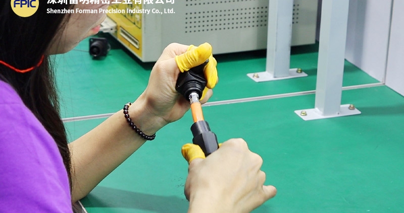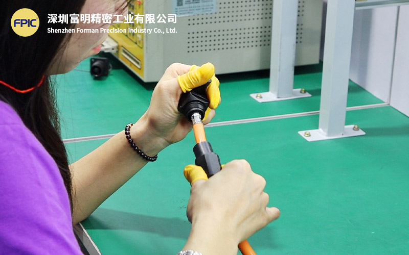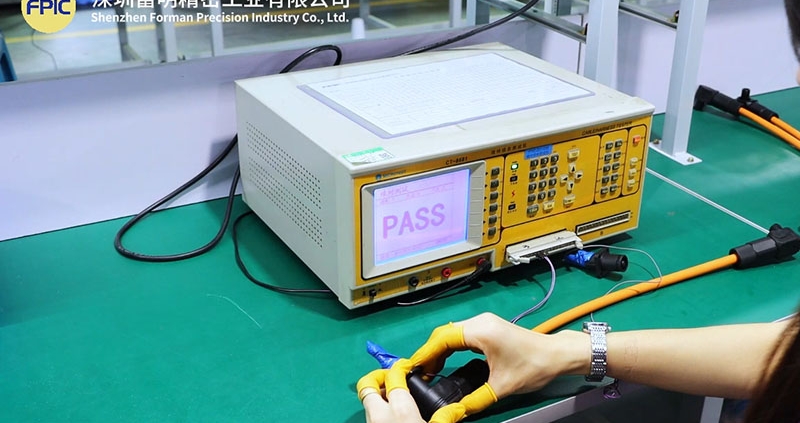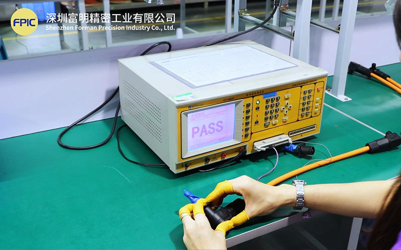
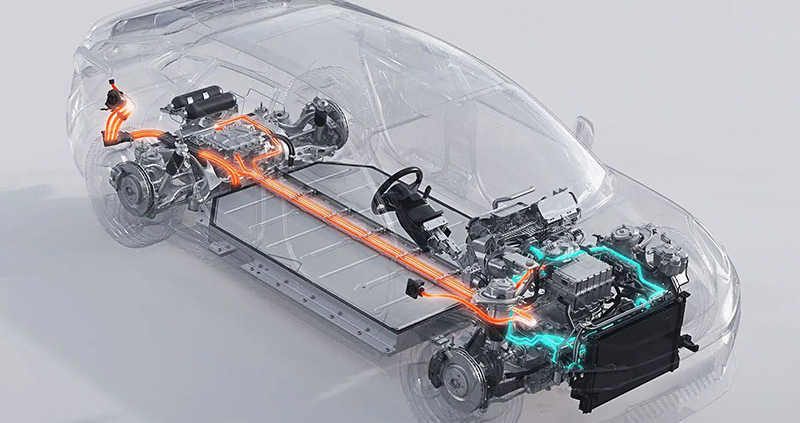
Automotive connector

Automotive connector operate in some of the most demanding environments found in engineering applications. From high vibration and temperature cycling to humidity, contamination, and long service life expectations, connectors must maintain stable electrical and mechanical performance over years of operation.

To ensure this reliability, OEMs and Tier 1 suppliers rely on structured validation standards such as LV214 and USCAR. However, passing standard validation tests does not always guarantee real-world durability. A robust connector validation plan must bridge the gap between laboratory testing and actual field conditions.

This article explains how LV214 and USCAR frameworks are applied, and how to build a validation strategy that reflects real-world reliability requirements.


Why Connector Validation Is Critical in Automotive Systems

Modern vehicles integrate a wide range of electrical systems, including power distribution, sensor networks, communication interfaces, and high-voltage architectures. Connectors are critical interfaces within these systems.

A failure at the connector level can lead to:

  • intermittent signal loss
  • increased contact resistance
  • thermal buildup and potential damage
  • system malfunction or shutdown

Unlike many components, connectors are exposed interfaces. They must tolerate mechanical stress, environmental exposure, and repeated mating cycles while maintaining stable performance.
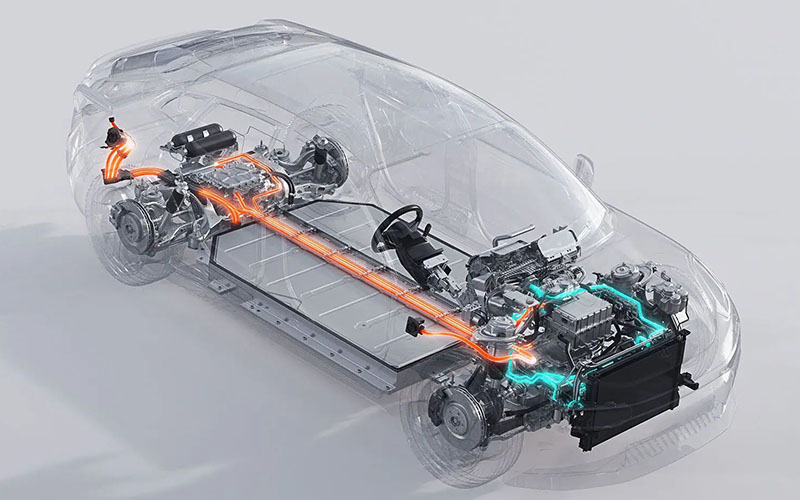
Automotive connector


Overview of LV214 and USCAR Standards

Two widely used frameworks define automotive connector validation requirements: LV214 and USCAR.

LV214: European OEM Validation Framework

LV214 is a comprehensive standard developed by major European OEMs. It defines test sequences and performance requirements for electrical connector systems.

Key features of LV214 include:

  • application-specific test classes
  • combined environmental and mechanical testing
  • sequential validation procedures
  • defined acceptance criteria

LV214 emphasizes realistic stress combinations, ensuring connectors are evaluated under conditions that simulate actual vehicle operation.


USCAR: North American Performance Specifications

USCAR standards, widely used in North America, define performance-based validation methods for connectors and terminals.

Typical USCAR test categories include:

  • thermal cycling
  • vibration testing
  • electrical performance verification
  • sealing and environmental resistance

USCAR standards are modular, allowing engineers to select relevant tests based on application requirements.


Key Validation Tests for Automotive Connectors

A robust validation plan typically includes a combination of electrical, mechanical, and environmental tests.

Electrical Performance Testing

Electrical validation ensures that the connector maintains stable signal and power transmission.

Common tests include:

  • contact resistance measurement
  • current carrying capability
  • insulation resistance
  • voltage drop analysis

Even small changes in contact resistance can indicate long-term degradation.


Mechanical Durability Testing

Mechanical testing evaluates how connectors perform under physical stress.

Typical tests include:

  • mating and unmating cycles
  • terminal retention force
  • connector locking strength
  • vibration resistance

These tests simulate installation, service, and vehicle operation conditions.


Environmental Testing

Environmental factors are a major source of connector failure.

Validation often includes:

  • temperature cycling
  • humidity exposure
  • salt spray testing
  • dust and water ingress (IP rating)

These tests assess how connectors perform in real-world environments such as engine compartments or exterior installations.
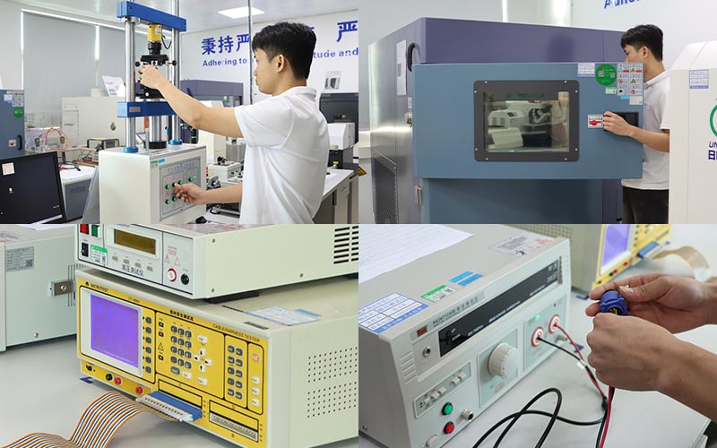
Automotive connector


The Gap Between Validation and Real-World Performance

While LV214 and USCAR provide structured validation frameworks, real-world failures still occur. This gap often arises because:

  • test conditions are simplified compared to real use
  • stress factors may occur simultaneously rather than sequentially
  • installation variability is not fully captured
  • long-term aging effects are difficult to simulate

For example, a connector may pass vibration testing and thermal cycling individually, but fail when both stresses are applied simultaneously over extended periods.


Designing for Real-World Reliability

To improve real-world performance, validation plans should go beyond minimum requirements.

Combine Stress Conditions

Instead of testing factors separately, combine:

  • vibration with temperature cycling
  • humidity with electrical load
  • mechanical stress with environmental exposure

This approach better reflects actual operating conditions.


Consider Application-Specific Risks

Different applications require different validation focus:

  • engine bay: high temperature and contamination
  • chassis: vibration and moisture
  • interior: lower environmental stress but higher mating cycles

Tailoring validation to the application improves reliability.


Evaluate Connector System Integration

Connector performance is influenced by more than the connector itself. Factors include:

  • wire harness routing
  • terminal crimp quality
  • sealing design
  • mounting conditions

A system-level approach ensures all interfaces are considered.


How FPIC Supports Connector Validation Projects

In automotive and industrial applications, connector reliability depends on both component quality and integration design.

FPIC supports connector and cable assembly projects with:

  • application-based design review
  • connector and terminal selection support
  • validation planning assistance
  • prototype development and testing coordination

By aligning design and validation early, FPIC helps reduce risk and improve long-term performance.


Final Thoughts

LV214 and USCAR provide strong foundations for automotive connector validation, but they should not be treated as checklists alone. Real-world reliability requires a deeper understanding of how connectors behave under combined stress, installation variability, and long-term use.

A well-structured validation plan considers both standard requirements and application-specific conditions. By doing so, engineers can ensure connectors perform reliably not just in testing, but throughout the entire lifecycle of the vehicle.


FAQ

What is LV214 in automotive connector testing?

LV214 is a validation standard used by European OEMs that defines test procedures and performance requirements for electrical connector systems.

What does USCAR stand for?

USCAR stands for United States Council for Automotive Research, which develops performance standards for automotive components including connectors.

Why do connectors fail even after passing validation tests?

Failures can occur because real-world conditions involve combined stresses, installation variation, and long-term aging that may not be fully replicated in standard tests.

What is the most critical connector test?

There is no single most critical test. Reliability depends on a combination of electrical, mechanical, and environmental validation.

How can connector reliability be improved?

By combining test conditions, tailoring validation to the application, and considering system-level integration factors.


Need Support for Automotive Connector Validation?

If you’re developing automotive or industrial systems, a well-planned connector validation strategy can reduce failure risk and improve product reliability.

FPIC provides custom connector and cable assembly solutions with engineering support from design through validation.

Contact FPIC to discuss your project requirements and validation needs.


Resources

  1. LV214 Standard Overview: outlines validation concepts and requirements used by European OEMs for electrical connector systems.
  2. USCAR Connector Performance Specifications: provides detailed testing procedures and performance requirements for automotive connectors.
  3. TE Connectivity – Connector Reliability Guide: explains connector design, testing, and reliability considerations in automotive environments.
  4. Molex – Automotive Connector Testing: covers validation methods and environmental testing for automotive connectors.
  5. Amphenol Automotive Solutions: offers insight into connector performance requirements and application-specific solutions.
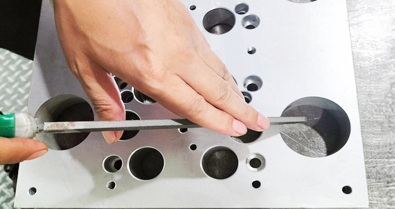
metal mold assembly

Introduction

Metal stamping molds are essential in manufacturing industries, enabling precise and efficient production of metal components. The mold assembly process plays a critical role in ensuring the quality, durability, and accuracy of stamped parts.

In this article, we will walk you through the complete metal stamping mold assembly process, covering essential steps, best practices, and quality control measures. Whether you are a mold engineer, manufacturer, or industry professional, this guide will provide valuable insights into achieving high-performance stamping molds.

I. Pre-Assembly Preparation

Before starting the assembly process, it is crucial to prepare the necessary tools, measuring instruments, and reference documents to ensure smooth execution.

1. Tools & Measuring Instruments

Ensure that the required tools and measuring instruments are available, including:

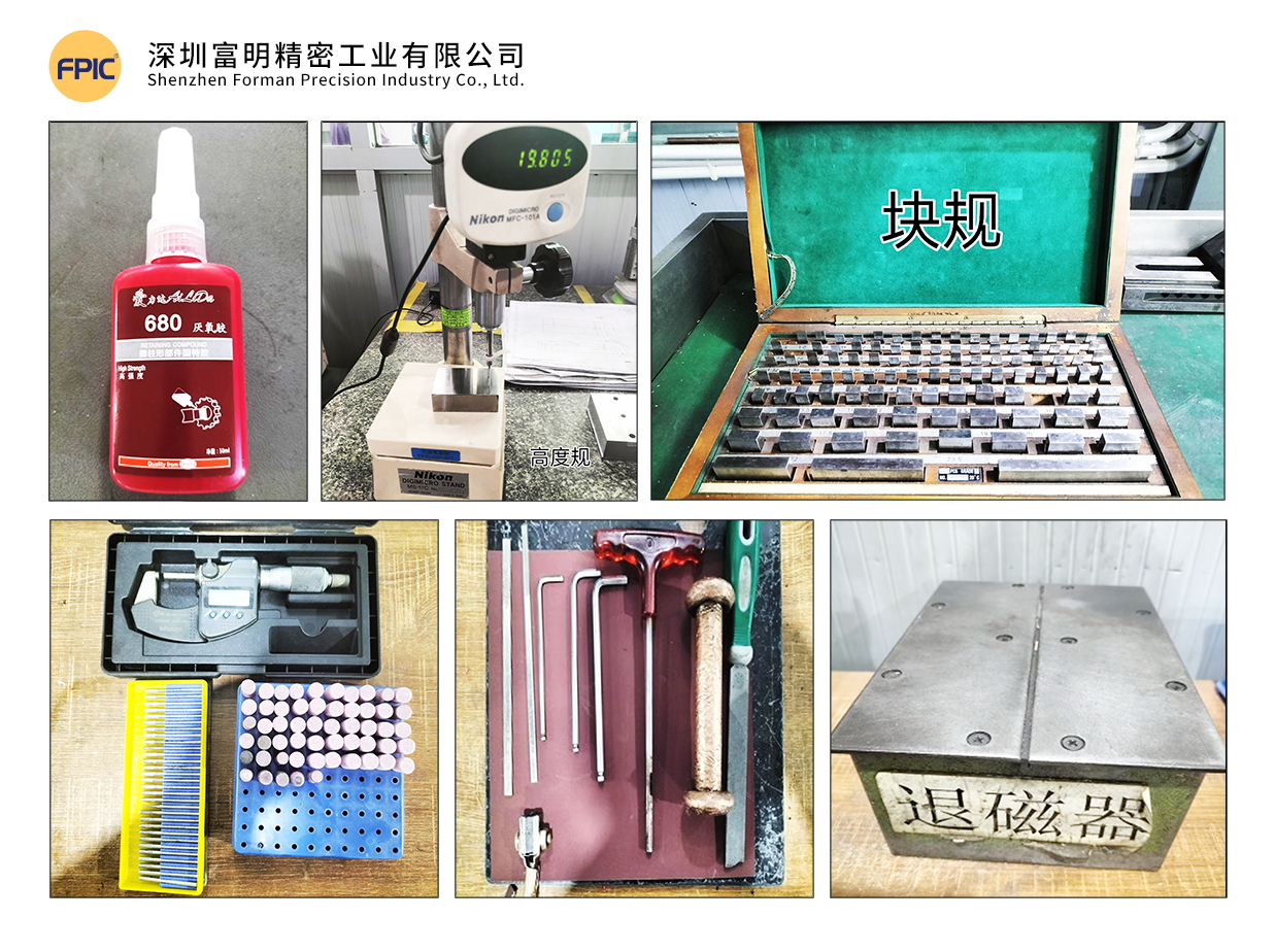
  • Hand tools: Wrenches, files, copper hammers
  • Surface finishing tools: Oil stones, sandpaper, pneumatic grinders, polishing heads
  • Cleaning agents: Mold cleaner
  • Adhesives & lubricants: 680 glue
  • Measuring instruments: Vernier calipers, micrometers, gauge blocks, thin shims, demagnetizer, etc.mold tools

2. Understanding the Mold

Before assembly, review all relevant drawings:

  • Product drawings
  • Layout drawings
  • Mold part drawings

3. Mold Assembly Process Overview

Familiarize yourself with the entire mold assembly process:

  1. Main Plate Gluing (Clamping Plate + Stripper Plate + Bottom Plate)
  2. Template Assembly
  3. Clamping Plate Component Assembly
  4. Stripper Plate Assembly
  5. Bottom Plate Assembly
  6. Upper & Lower Mold Matching & Confirmation
  7. Mold Base Gluing (Upper & Lower Mold Base)
  8. Installation of Standard Components
  9. Trial Stamping & Sample Testing


II. Template & Component Inspection Before Assembly

1. Template Inspection

✅ Material & Hardness Verification: Ensure templates have undergone deep-freezing and stabilization treatment.
✅ Flatness & Warping Check: Warping should not exceed 0.005mm per 100mm.
✅ Hole Position & Processing Accuracy: Verify drilled holes, allowances, and surface finish.
✅ Screw Hole Depth & Alignment: Check threaded hole depth and perpendicularity for proper fastener fitment.
✅ Embossing & Pressing Grooves: Ensure correct width and depth.
✅ Labeling & Marking: Verify mold number, material width, pitch, and part name.

2. Component Inspection

  • Material, Quantity & Hardness Verification
  • Dimensional Accuracy Check

Proper inspection eliminates potential errors that could cause misalignment, improper fits, and structural weaknesses in the final mold.

III. Template Machining & Finishing

1. Mold Base Preparation

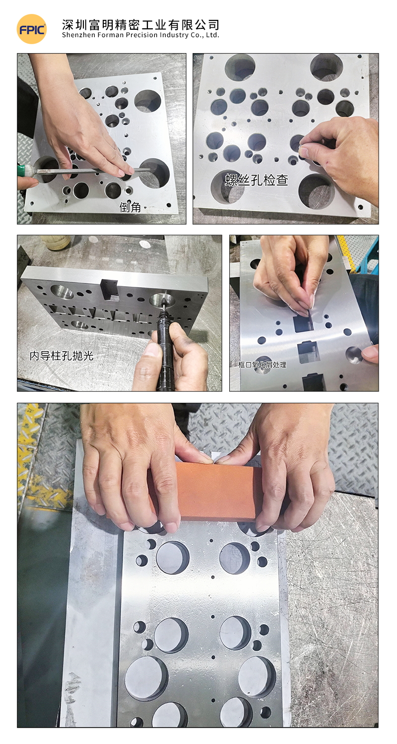
  • Clean all threaded holes of debris; check for damaged or unthreaded holes.
  • Deburr sharp edges and corners using a flat file.
  • Polish the surface with an oil stone to remove burrs.

2. Hole Deburring & Edge Rounding

  • Use round oil stones, files, grinders, and sandpaper for chamfering insert holes, round holes, and square holes.
  • Remove oxidation residues from wire-cut holes using fiber oil stones and round rods.

3. Surface Finishing

  • Polish the template with fine oil stones in the direction of the grinding pattern.
  • Use lubricating oil during polishing to prevent scratches.Mold Base & Template Finishing

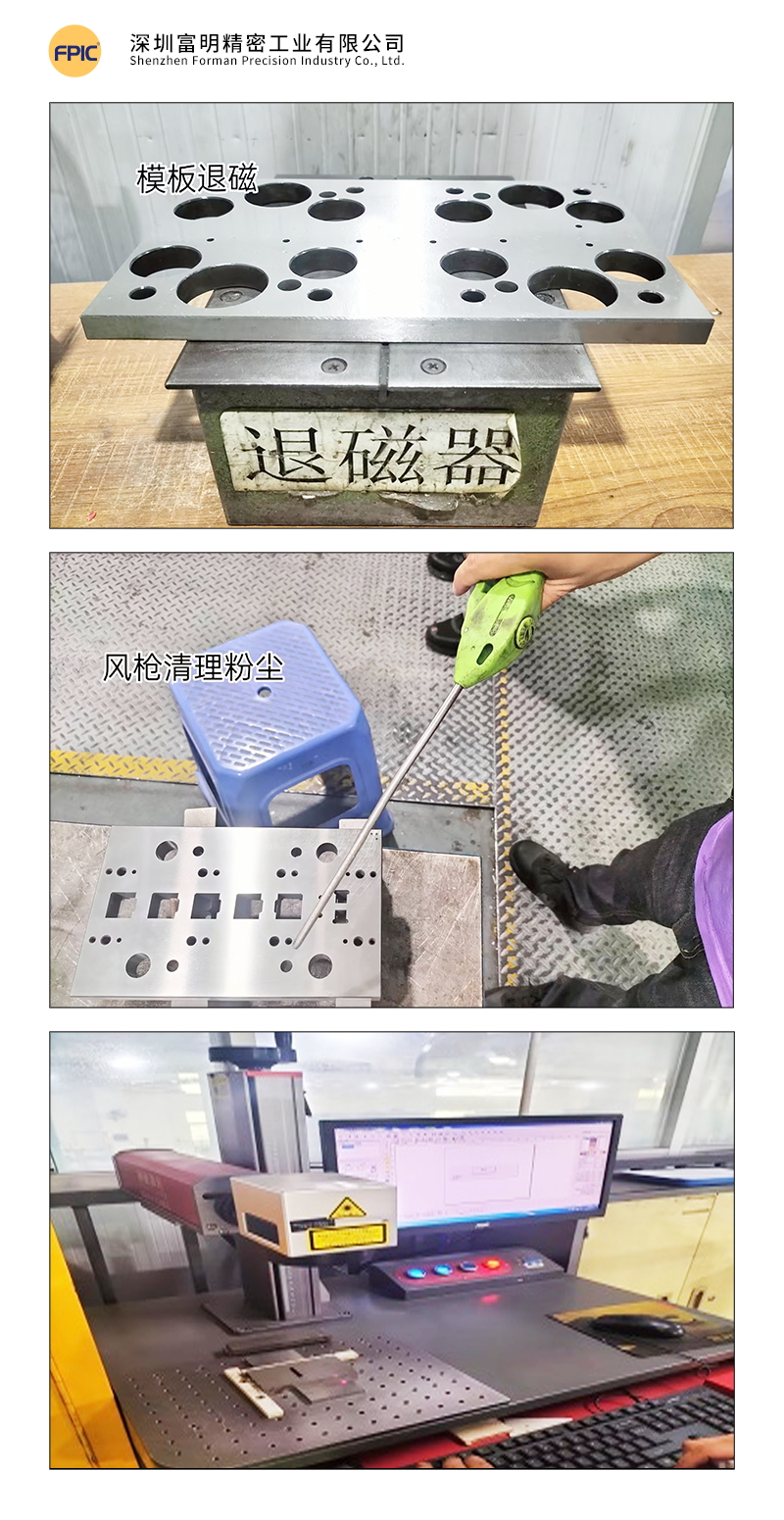
4. Demagnetization

  • Use a demagnetizer to remove magnetism from the mold base and all components to prevent iron powder absorption, which could affect assembly accuracy.

5. Cleaning

  • Clean templates thoroughly using mold cleaner and compressed air.
  • Precision mold assembly requires a high level of cleanliness to ensure optimal performance.

6. Component Handling

  • Engrave part numbers on components.
  • Add lead-in angles to guide posts.
  • Sort, match, and demagnetize all parts.mold cleaning

Tip: Precision molds require extreme cleanliness to prevent defects in stamped parts.

IV. Measurement & Alignment Verification

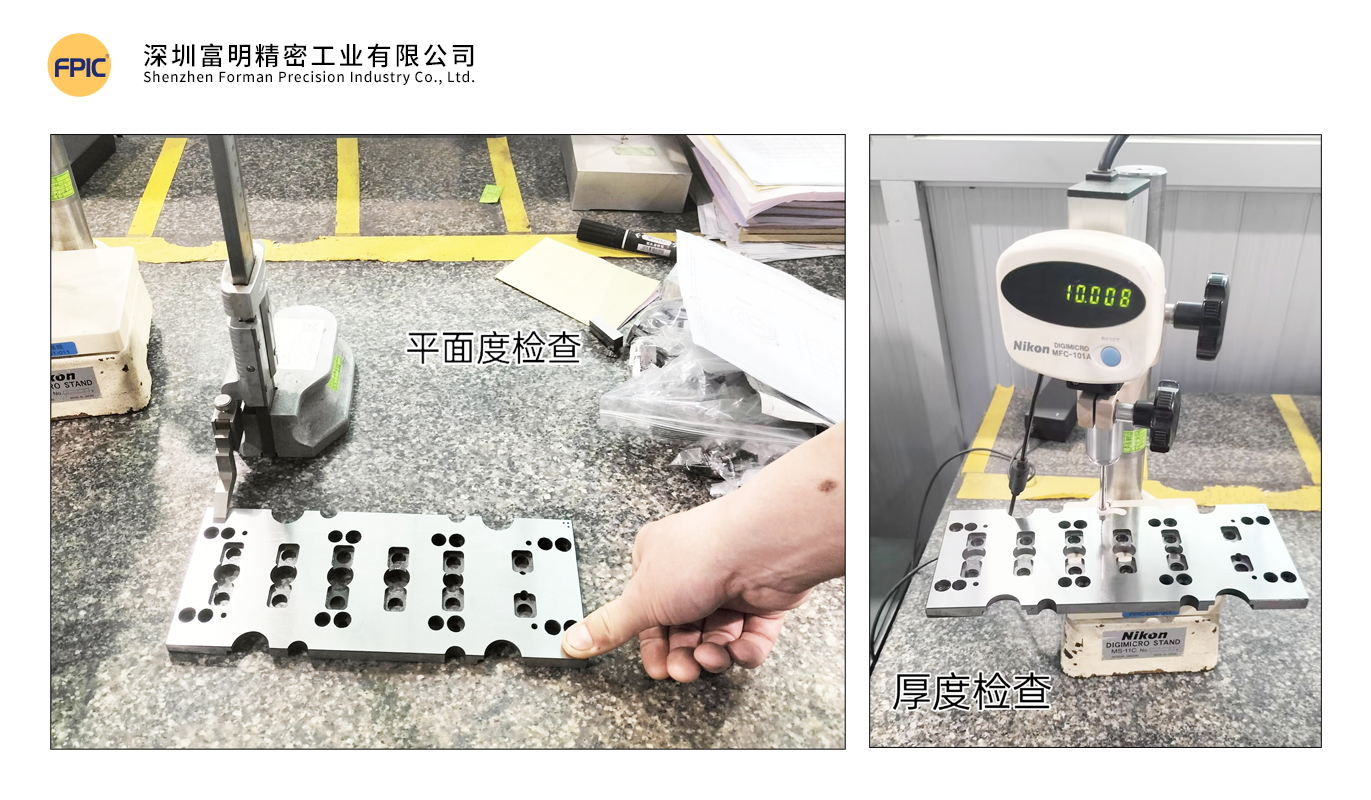
1. Template Parallelism Measurement

  • Fix a dial indicator to zero on a reference platform and measure.
  • Standard tolerance: ≤ 0.002mm.

2. Template Warping & Deformation Check

  • Press one end of the template and observe dial indicator changes at the other end.
  • Deformation should not exceed 0.003mm.

3. Main Template Parallelism & Warping Measurement

  • Tolerance should not exceed 0.005mm.

4. Guide Post & Guide Bushing Measurement

  • Ensure guide posts conform to the required dimensions and roundness.
  • Measure guide post fitment and machining accuracy per the drawings.Measurement & Quality Control

V. Mold Gluing Process

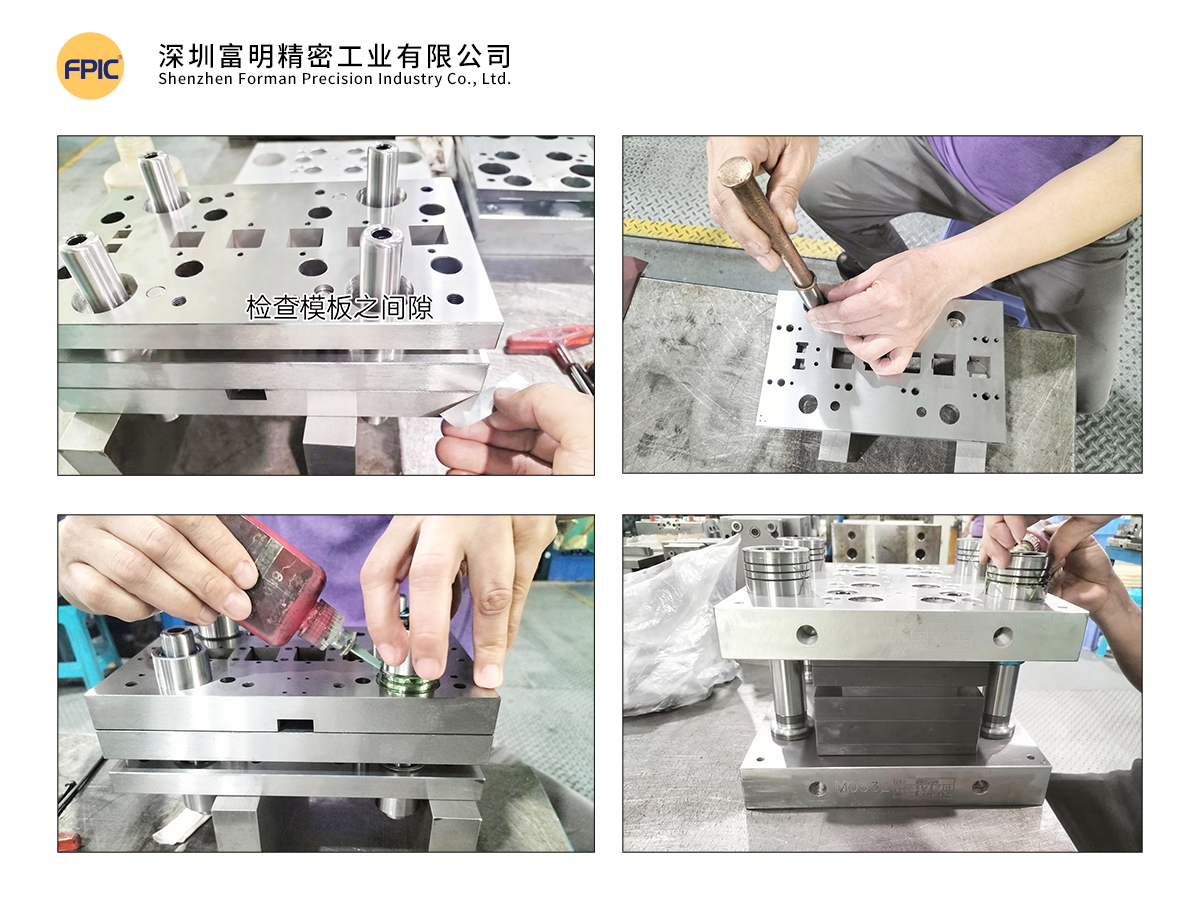
1. Gluing Steps

Step 1:

  • Use 0.005mm shims to check for gaps after mold closure.
  • The mold is qualified when shims cannot enter the gap.

Step 2:

  • After confirming the main template, insert a 10mm positioning pin from the clamping plate to the bottom plate to align the three primary templates.
  • If any gaps exist, check for debris or interference before proceeding.

Step 3:

  • Clean guide post and guide bushing thoroughly.
  • Insert guide posts into the stripper plate and secure with screws.
  • Place 0.2mm steel shims in each guide bushing hole.

Step 4:

  • Apply 680 glue evenly on the guide bushings while rotating them for even distribution.
  • Slowly insert guide bushings into the template until they rest against the steel shims.
  • Repeat for all guide bushings.Mold Gluing ProcessVI. Standard Component Assembly
1. Standard Component Inspection

  • Verify that all standard parts meet specifications.

2. Height & Position Check

  • Confirm the heights of floating pins, equal-height sleeves, limit posts, guide pins, and ejector rods.

3. Standard Component Installation

  • Clean all round holes before inserting components.
  • Install components into the mold cavity in order.

4. Final Confirmation

  • Ensure all parts are flat and properly fitted.
  • Verify free movement of standard components.
  • Check for clogged scrap ejection holes.
  • Ensure adjustment rods are correctly positioned and do not interfere with other templates.

VII. Mold Testing & Issue Documentation

1. Mold Closure Height Verification

  • Record closure height in the Mold Testing & Issue Report.

2. Manual Mold Closure Test

  • Close the mold manually to check for proper spring compression.

3. Trial Stamping & Sample Testing

  • Record initial data for comparison in subsequent trials.
  • Repeat trials until samples meet specifications.

4. Issue Analysis & Data Collection

  • Document all design & machining issues.
  • Analyze the root cause and record corrective actions.
  • Collect data for future design optimizations.

Example: Mold Testing & Issue Report

Date Issue Description Corrective Action Design Issue Machining Issue Resolution Date Result Responsible Person
2.18 Tight-fitting D07 forming part Wire-cut rework ✔ 2.18 Normal Engineer A
2.19 S05 part causing ejection failure Added ejector structure ✔ 2.19 Normal Engineer B
2.19 Dimension 2.02mm undersized Added 0.02mm shim ✔ 2.19 Normal Engineer B
2.20 Sent for FAI inspection 2.20 QA Inspector

 Note: All mold trials must be fully documented, ensuring a complete history of deviations and corrective actions.

Conclusion

The metal stamping mold assembly process requires precision, attention to detail, and strict quality control to ensure high-performance and long-lasting molds. By following these structured steps—from pre-assembly preparation to final testing—manufacturers can optimize efficiency, reduce downtime, and improve mold longevity.

Implementing these best practices will help ensure high-quality stamped parts, reducing waste, rework, and production costs.

Looking for High-Quality Metal Stamping Solutions?

At FPIC, we specialize in precision mold manufacturing with a focus on quality, efficiency, and innovation. Contact us today to learn more about our custom mold solutions!

Get in touch with us today!

metal stamping mold

Metal stamping is a crucial manufacturing process, shaping raw materials into precision components used across various industries. At the heart of this process are the metal stamping molds, instrumental in achieving consistency, accuracy, and efficiency in production. The standardization of these molds plays a pivotal role in elevating the quality of stamped parts and streamlining the entire manufacturing workflow.

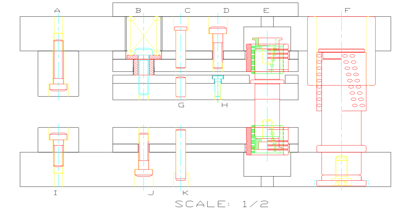
1. Mold Design Standard Structural Diagram
metal stamping molds

No. Standard Parts Diagram
A Upper Limit High Pillar: Functions to ensure the precision of mold closure and prevent parts from being damaged.
B Upper Mold Spring and Equi-height Sleeve: Functions to aid in ejecting the molded part
C Upper Mold Pin: Functions to precisely fix and locate the upper mold base, upper bolster, and clamp plate.
D Upper Mold Screw: Functions to secure the mold plate.
E Misumi Inner Guide Post and Guide Sleeve: Functions to bear the precision of the entire set of mold components.
F Misumi Outer Guide Post and Guide Sleeve: Functions to bear the precision of mold components and ensure alignment between upper and lower molds.
G Ejector Pin: Functions to fix and position the fixed plate and ejector plate.
H Ejector Screw: Functions to secure the mold plate.
I Lower Limit High Pillar: Functions to ensure the precision of mold closure and prevent parts from being damaged.
J Lower Mold Screw: Functions to secure the lower mold plate.
K Lower Mold Pin: Functions to precisely fix and locate the lower mold base, lower bolster, and lower mold seat.

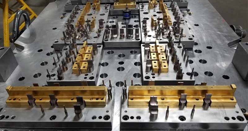
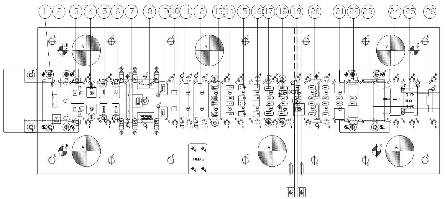
2. Standard Specifications for the Layout of Material Strips in Mold DesignLayout of Material Strips in Mold Design

No. Layout Diagram
1 Holes with high positional tolerance requirements or those prone to breakage need to be punched simultaneously; as shown in figures 1/2.
2 If there are holes for bending or other processes with high positional accuracy requirements, punch them after bending.

This can avoid inaccuracies in unfolding that may affect dimensions; as shown in figures 11/12 for bending, and figure 13 for cutting after bending.

3 In cases where there is symmetrical bending in the product, synchronous bending needs to be designed; as shown in figures 21/22/23.
4 Processes like stretching or others that may affect dimensions during forming need to be addressed in advance;

as shown in figure 10 with stretching first, followed by forming in figures 15/16.

5 For variations in the production process, adjustments to parts need to be increased, reducing the need for maintenance of the

lower mold during production; as shown in figure 19.

3. Design Standards for Mold Components

Cutting Station Design Standards

  • The drawing should specify the processing technology, where K represents fast cutting, M represents slow cutting, Y represents grinding, F represents discharge machining, X represents milling, PG represents wire cutting, and YG represents oil cutting. For precision blade drawings, the requirements are YG oil cutting – Y grinding – F discharge machining.
  • Material selection for components, such as ASP23, ASP60, WC, DC53, SKD11, SKH-9, SKH-53. Different materials should be applied based on the characteristics of the plate. For cutting punches, ASP60 with an HRC of 62 degrees is prioritized.
  • For soft materials with a thickness t < 1MM, the blade gap is c = (3%-4%) t; for t = 1MM-3MM, the blade gap is c = (5%-8%) t; for t = 3MM-5MM, the blade gap is c = (8%-10%) t.
  • For hard materials with a thickness t < 1MM, the blade gap is c = (4%-5%) t; for t = 1MM-3MM, the blade gap is c = (6%-8%) t; for t = 3MM-8MM, the blade gap is c = (8%-13%) t.
  • Try to avoid designing rectangular punches, as rectangular punches are prone to waste jumping.
  • For blade widths less than 1.0mm (round holes less than 1.0mm in diameter), for easy processing and improved accuracy, the blades need to be processed separately.
  • Punches should avoid excessively long and narrow grooves, and sharp corners should be avoided as much as possible. The length of small punches should be kept as short as possible, with appropriate reinforcement added.
  • Punches should be designed with an anti-stripping structure, considering the reduction of discharge machining.

    Design Standards for Forming Components
    Standard for the fit clearance of forming punches, standard for the springback parameters of parts with R-angle bending, referring to the “Springback Value Table.” Depending on the hardness of the material, the greater the hardness, the larger the values can be.

    Springback Standard for R≤5 Bending

    Material Thickness Bending Angle
    >90° <90° 90° Empty
    Stainless steel Phosphor/ Bronze/ Beryllium copper T<0.3mm 3°-5° 2°-4° 0.1-0.2° 5°-10°
    T>0.3mm 2°-4° 2°-3° 0.1-0.2° 4°-8°
    Iron material/ Bronze/Red copper T<0.3mm 1°-3° 2°-3° 0.1-0.2° 2°-4°
    T>0.3mm 1°-2° 1°-2° 0.1-0.2° 1°-3°

4. Template Block Design and Processing Standards

  • Precision requirements for template processing: machining tolerances and special manufacturing processes.
  • For template templates longer than 500mm, split design is required; all molds need to have process reference holes.
  • The processing accuracy of mold template parts in the whole set is required to be controlled within ±0.01mm, and the surface roughness of the template is required to be less than 0.4um.
  • For the blanking holes, stacking bodies, and oil cutting of the blanking plate and lower template, all fixed pin holes are treated with JG grinding; the sliding fit clearance C+ (0.005-0.010mm), non-sliding fit clearance C+0.003mm, machining accuracy ±0.002mm.
  • For the upper template, blanking plate, and lower template, the use of Misumi internal guide pins and guide bushes filled with glue improves guiding accuracy to ensure the positional accuracy of the template during production.
  • After heat treatment, the template undergoes super-deep cryogenic aging treatment, and some may require stabilization treatment to eliminate internal stress, prevent grinding deformation, and ensure template flatness of 0.005mm.

5. Mold Inspection Requirements

  • Verify that punches, inserts, dimensions of template length, and thickness conform to the drawing specifications.
  • Check the condition of screw holes and threading; assess the fit clearance of internal and external guide pillars; inspect for any missed wire cutting.
  • Measure the thickness dimensions of the template, and a difference of within 0.005mm in four-point measurements is considered acceptable.
  • Inspect the relinquishment processing status; ensure that the hole diameters and counterbore depths of various template through-holes comply with the drawing specifications.
  • Examine whether each hole is eccentric, assess the alignment of templates, and check the normality of positioning pins.
  • Apply chamfering to the periphery of the template. Include mold identification details on the sides, such as mold number, part number, material code, pitch, material width, mold closing height, and other parameters.

6. Mold Assembly Standards

  • Mold assembly is divided into two parts, upper and lower, assembled separately, and finally, the upper and lower molds are assembled together.
  • Firstly, understand the mold drawings, product information, analyze the mold structure, and comprehend the design intent of the mold.
  • Chamfer, polish, engrave, and categorize the templates and parts.
  • Use specialized positioning tools for installing internal and external guide pins and bushings to ensure their verticality during the positioning and gluing process.
  • Ensure smooth assembly of punches and block pairs, and appropriate force when tapping parts.

7. Mold Spare Parts Detailed Management

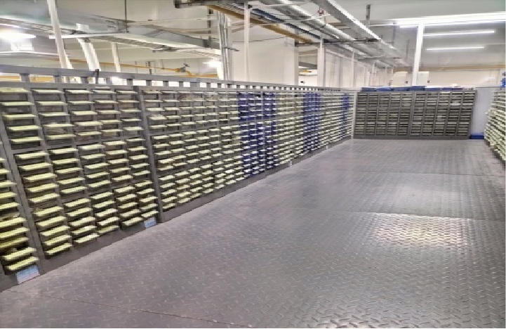
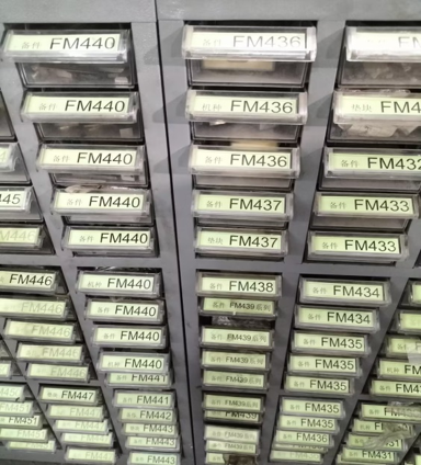
For molds accommodating multiple machine types, each part is assigned a unique number for clear and separate storage. This facilitates efficient replacement during the production process, expedites effective mold assembly, and reduces downtime during the production line changeover.

Spare Part Temporary Storage Area       Spare Parts Temporary Storage Area

Figure 1: Spare Part Temporary Storage Area

Parts are systematically arranged for easy visibility and subdivided into spare parts, blade components, machine-specific parts, molding parts, and standard components.

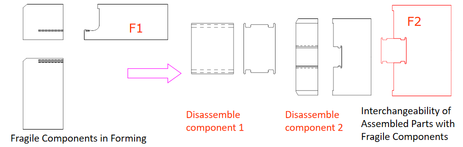
8. Continuously Optimize Part Structures, Validated Parts as Design Standards

Emphasizing technological innovation in designing parts: Figure 1 depicts a symmetric part that, once subjected to bending wear during the production process, becomes unusable. In Figure 2, a design optimization involves disassembling the part and redesigning the bending position as a double-sided molded part. Wear can be mitigated by turning to the other side for forming, effectively reducing processing costs and production downtime.

Optimize Part Structures

Conclusion:

In the dynamic landscape of metal stamping, the standardization of molds emerges as a cornerstone for operational excellence. It not only ensures the reliable production of high-quality parts but also positions manufacturers to adapt swiftly to industry advancements. As technology continues to reshape the manufacturing landscape, the role of standardized metal stamping molds becomes increasingly critical in driving efficiency, precision, and overall competitiveness.

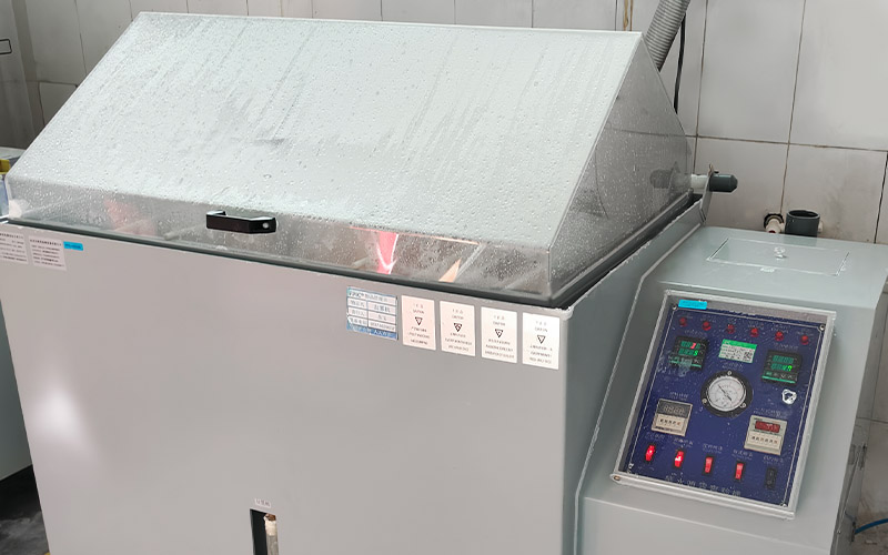
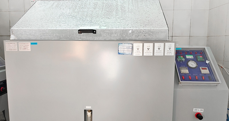
salt spray test machine

Automotive connectors are the unsung heroes behind modern vehicle electronics. From lighting control to infotainment, these tiny components ensure secure signal and power transmission in environments that are anything but gentle. Moisture, vibration, high temperatures — and especially salt — are constant threats. That’s why the salt spray test is a vital benchmark in ensuring durability and long-term performance.


What Is a Salt Spray Test?

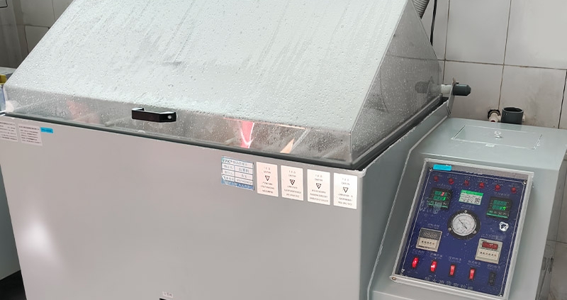
A salt spray test (or salt fog test) is a laboratory procedure used to evaluate the corrosion resistance of materials and coatings. Connectors are placed in a sealed chamber filled with a fine mist of 5% salt solution, replicating years of exposure to harsh environmental conditions like road salt, coastal air, and chemical spray — all common in real-world automotive scenarios.

This test runs for 48, 72, or even 96 hours, with results used to validate how well a connector can withstand corrosion without compromising its structural or electrical integrity.

salt spray test machine


Why the Salt Spray Test Matters in Automotive Connectors

1. Corrosion Resistance = System Reliability

A corroded pin or terminal increases electrical resistance, which leads to signal loss, power fluctuation, or complete failure. Salt spray testing ensures that your connectors will stay conductive and safe, even in salt-rich environments like snowy roads or coastal regions.

2. Protection for Critical Functions

Whether it’s lighting control, power seats, electric windows, or multimedia systems, FPIC automotive connectors are designed to maintain stable performance under extreme conditions. A failed connector in these systems could mean malfunctioning lights or unresponsive controls—and customer dissatisfaction.

3. EV-Ready and High-Voltage Capable

As new energy vehicles (NEVs) become mainstream, FPIC is also investing in the development of high-voltage automotive connectors. These require even higher resistance to corrosion, as failure in high-voltage components could compromise vehicle safety and efficiency.

Salt spray testing is an essential part of validating these next-gen products for long-term field use.

4. Meeting Global Automotive Standards

Passing salt spray tests is a requirement for many OEM and Tier 1 customers who demand compliance with IATF 16949 and other international quality standards. FPIC’s automotive connectors are tested to withstand up to 96 hours of salt spray, providing proven reliability and performance.

5. Confidence for Global Applications

From the icy roads of Scandinavia to the humid coasts of Southeast Asia, salt and corrosion vary by geography. By passing this test, FPIC connectors are validated for use in global automotive platforms, regardless of climate or terrain.


How FPIC Delivers Reliable, Corrosion-Resistant Connector Solutions

At FPIC, we provide complete connector solutions for:

  • Lighting systems (headlights, taillights, ambient lighting)

  • Seat control modules and heating units

  • Power window lift systems

  • In-car multimedia and infotainment applications

  • High-voltage connections for EV platforms

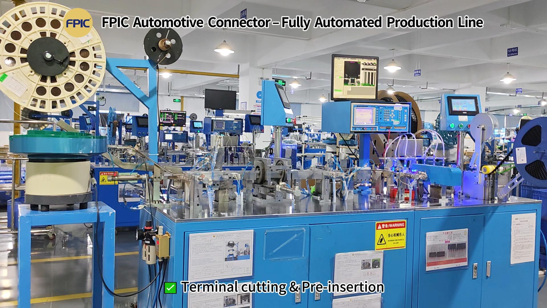
Our connectors are manufactured in fully automated production lines, with processes that include:

  • Terminal forming, bending, and riveting

  • Electrical performance testing

  • CCD vision inspection for size, alignment, and appearance

  • Tape & reel packaging for SMT-ready handling

Every product undergoes strict quality checks — and is backed by our zero-risk custom development promise, ensuring you receive a solution tailored to your needs without compromise.

Automotive connector production process--new


Conclusion: Salt Spray Testing Is Not Optional — It’s Essential

The salt spray test may take place in a lab, but its impact is felt on every road, in every climate, and across every application. For FPIC, passing this test is not just about compliance — it’s about delivering automotive connectors that customers can trust in every condition.

When performance matters, and corrosion is the enemy, choose FPIC—where durability is engineered, tested, and proven.

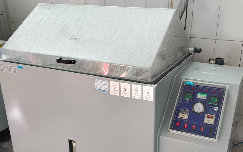
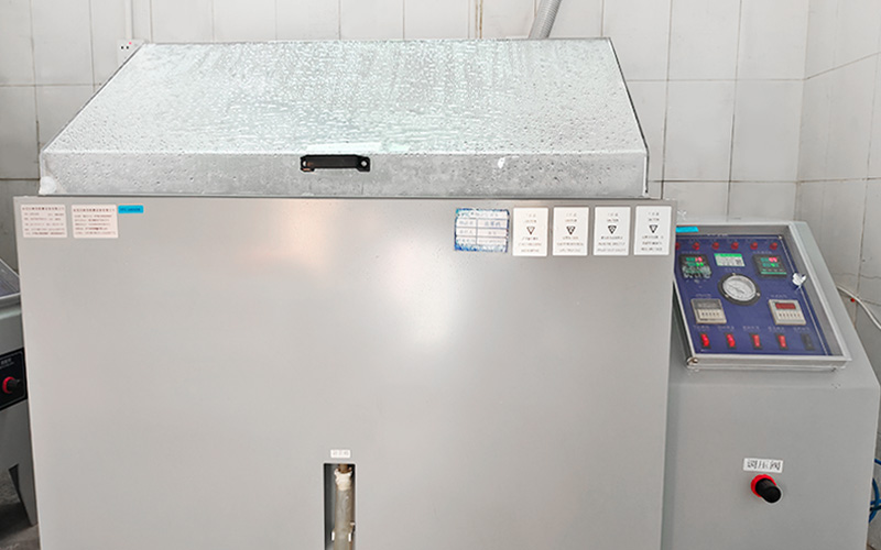
Salt spray test standard

In the demanding world of automotive engineering, connector reliability is critical. Vehicles operate in harsh environments where temperature fluctuations, road salts, moisture, and chemical exposure can compromise connector performance over time. One of the most trusted indicators of corrosion resistance is the salt spray test—an essential part of automotive connector validation.


? What Is Salt Spray Testing?

Salt spray testing, also known as salt fog testing, is a standardized corrosion test used to evaluate the resistance of surface coatings to a saline environment. It simulates accelerated aging to predict how materials and coatings will perform in long-term real-world conditions.

The test exposes connectors or components to a continuous saline mist (typically 5% NaCl solution) inside a sealed chamber at 35°C (95°F). Components are evaluated over hours or days depending on the test standard and product requirements.


? Common Salt Spray Test Standards in the Automotive Industry

Automotive manufacturers follow strict standards to ensure product durability. Some of the most widely accepted test protocols include:

  • ISO 9227 (NSS Test) – Neutral salt spray, globally recognized.

  • ASTM B117 – Commonly used across industries for corrosion testing.

  • IEC 60068-2-11 – For environmental testing of electrical equipment.

  • JIS Z 2371 – Japanese industrial standard for salt spray resistance.

  • OEM-Specific Standards – Like VW PV1210, Ford CETP, or GM GMW 3172, which include extended test durations and failure criteria.
    salt spray test machine Salt spray test standard


? Why Salt Spray Resistance Matters for Automotive Connectors

Automotive connectors are exposed to corrosive elements such as:

  • De-icing road salts

  • Humidity and water ingress

  • Engine fluids and chemicals

  • High-vibration environments

Corrosion can degrade conductivity, cause signal loss, increase contact resistance, and eventually lead to electrical failure. That’s why compliance with salt spray performance standards is crucial for any connector used in:

  • Powertrain systems

  • Battery electric vehicles (BEVs)

  • Energy storage modules

  • Sensor and control circuits

  • EV charging systems


? Forman’s Salt Spray Testing Capabilities

At Forman Precision Industry Co., Ltd., our automotive-grade connectors undergo rigorous in-house salt spray testing to ensure:

✅ 96 hours salt spray resistance under neutral conditions (NSS test)
✅ No visible corrosion or performance degradation
✅ Full compliance with IATF 16949 quality standards
✅ Corrosion-resistant coatings for long-term stability
✅ Application-specific design and prototyping support


? Our In-House Testing Laboratory

Equipped with environmental test chambers, our lab performs:

  • Salt spray & humidity testing

  • Thermal cycling & vibration analysis

  • Contact resistance & insulation testing

  • Cross-section analysis after exposure

Every production batch follows strict process control and traceability, ensuring product reliability from prototyping to mass production.


? Application Areas

Forman’s salt spray-tested connectors are ideal for:

  • Automotive wiring harnesses

  • EV battery connectors

  • Energy storage solutions

  • Industrial automation systems

  • Heavy-duty transportation & off-road equipment


? Why Choose Forman?

✅ Over 20 years in precision connector manufacturing
✅ Certified: IATF 16949, ISO 9001, VDA 19.1, ISO 14001
✅ Custom connector solutions from concept to production
✅ Fully equipped in-house testing for fast validation
✅ Trusted by global OEMs and Tier 1 suppliers


? Ready to Improve Your Connector Durability?

Partner with Forman to develop corrosion-resistant, automotive-grade connectors built to perform.
? Contact us at info@fpiconn.com
? Learn more: www.fpiconn.com

Energy storage connector solutions

As the world transitions to a low-carbon future, energy storage systems (ESS) are becoming the cornerstone of modern power infrastructure. Whether supporting renewable energy, electric vehicles (EVs), or smart grids, the efficiency and reliability of these battery systems rely heavily on one often-overlooked component: the connector.

At Forman Precision Industry Co., Ltd (FPIC), we understand that high-performance energy storage connectors are not just accessories — they are essential to unlocking the full potential of battery technology. In this article, we explore the critical role that connectors play in advanced battery systems, the technologies behind them, and how we help customers deliver safer, smarter, and more efficient energy solutions.


Why Connectors Matter in Energy Storage Systems

Modern battery energy storage systems (BESS) must manage high voltage, high current, and intense thermal conditions — all while maintaining system integrity, safety, and longevity. The right energy storage connector:

  • Enables low-resistance power transmission

  • Ensures safe, secure connections under high voltage (often up to 1500V)

  • Simplifies maintenance and scalability

  • Supports modular battery pack design

  • Improves system uptime and reliability

Without high-quality, purpose-built connectors, energy storage systems risk voltage drops, heat generation, and even failure under dynamic operating conditions.


Key Types of Connectors in Battery Systems

? High-Voltage Battery Connectors

These are used in EV battery packs, grid-scale storage, and renewable energy systems. They’re engineered to support up to 1500V and currents from 100A to 350A or more, making contact resistance, insulation, and heat dissipation critical design considerations.

? Modular Energy Storage Connectors

Often used in lithium-ion battery modules and racks, these connectors allow for quick-disconnect, easy maintenance, and plug-and-play configurations — ideal for scalable ESS solutions.

? Power Connectors for Battery Management Systems (BMS)

These connectors provide signal and control data, ensuring real-time monitoring of battery temperature, voltage, and performance. They must offer stable contact, low noise, and shielding from electromagnetic interference.


Connector Design Factors that Influence Energy Storage Efficiency

✅ Current-Carrying Capacity

High-power energy storage connectors must be engineered for low contact resistance to avoid power loss and reduce heating, improving overall system efficiency and energy density.

✅ Thermal Management

Thermal buildup can damage batteries and reduce lifespan. Connectors designed with optimized conductor paths and heat-resistant materials improve safety and energy efficiency.

✅ Vibration & Shock Resistance

In mobile and industrial ESS applications, connectors must withstand mechanical stress, maintaining a secure connection without performance degradation.

✅ Ingress Protection (IP Ratings)

Connectors used in outdoor or industrial environments must meet IP67/IP68 standards, ensuring protection from dust, water, and contaminants.

✅ Material Quality

Premium copper alloys, gold-plated or silver-plated contacts, and high-performance thermoplastics are vital for corrosion resistance, conductivity, and long service life.


FPIC’s Energy Storage Connector Solutions

At FPIC, we deliver complete connector and cable assembly solutions designed specifically for battery storage and high-voltage applications.

? Custom Prototyping – Our engineering team works closely with clients to design and develop tailored connector solutions that match voltage, current, and installation needs.
? Cable Assembly Integration – We offer factory-assembled harnesses to reduce installation errors and support modular ESS deployment.
? In-House Testing – All products undergo stringent testing, including hipot testing, insulation resistance, salt spray, and temperature cycling, ensuring compliance with UL, TUV, and CE standards.
? Fast Sampling & Scalable Production – From pilot runs to mass manufacturing, FPIC supports your product launch and scale-up timelines.


Applications of Energy Storage Connectors

Our high-voltage energy storage connectors are widely used in:

  • Grid-tied energy storage systems

  • Solar and wind energy battery backup systems

  • Electric vehicle (EV) battery packs and charging stations

  • Uninterruptible power supplies (UPS)

  • Telecom power and industrial automation


End-to-End Value with FPIC

Choosing FPIC as your energy storage connector supplier means gaining a technology partner with deep experience in:

  • Connector R&D and precision manufacturing

  • Wire harness assembly and customization

  • System-level design support for modular battery applications

  • ISO 9001, ISO 14001, IATF 16949, and VDA 19.1 certified processes

We don’t just supply components — we build long-term connectivity solutions that drive performance, safety, and scalability.

Energy storage connector solutions


Conclusion

As energy storage continues to evolve and expand, the demand for smarter, safer, and more efficient connectors will only grow. The right high-voltage connector improves thermal performance, simplifies integration, and enhances the overall reliability of battery systems.

At Forman (FPIC), we are committed to driving energy innovation forward — one powerful connection at a time.

? Ready to advance your energy storage design? Contact us today at info@fpiconn.com or visit www.fpiconn.com to explore our solutions.

high voltage connectors test

As industries rapidly evolve towards electrification, renewable energy, and energy storage systems (ESS), the demand for high-voltage connectors with superior performance and uncompromised safety is higher than ever. At Forman Precision Industry Co., Ltd (Forman), we lead the way in high-voltage connector innovation, offering customers end-to-end solutions — from custom prototyping and sampling to full mass production, backed by our own in-house testing laboratory and assembly lines.

In this article, we explore the latest engineering innovations behind high-voltage connector design, and how Forman helps customers achieve better performance, greater safety, and faster time-to-market.

high voltage connectors test


The Need for Innovation in High-Voltage Connectors

Modern energy systems — whether in electric vehicles (EVs), battery storage systems, industrial automation, or solar power plants — require connectors that:

  • Handle higher voltages and currents safely

  • Operate reliably in harsh environments

  • Offer easy installation and maintenance

  • Meet international safety and quality standards

To meet these growing demands, connector design must continually advance with new materials, smarter structures, and tighter manufacturing tolerances.


Key Innovations Driving High-Voltage Connector Design

? 1. Advanced Insulation and Sealing Technologies

Today’s connectors must withstand up to 1500V or higher, demanding superior dielectric materials and multi-layer insulation structures.

  • Enhanced creepage and clearance distances to prevent arcing

  • IP67/IP68 sealing to protect against dust, water, and contaminants

  • Thermal-resistant materials to ensure stability in high-temperature environments

At Forman, we use advanced polymer compounds and precision molding techniques to achieve the highest insulation reliability.


? 2. Compact, High-Current Designs

Space-saving without sacrificing performance is key.

  • Optimized contact geometries to support higher current loads with lower resistance

  • Smaller form factors to fit into tight system architectures

  • Shielded designs to minimize electromagnetic interference (EMI)

Forman’s high-voltage connectors are engineered for maximum current density while maintaining excellent thermal management.


? 3. User-Centric Mechanical Designs

Ease of use is critical for efficient installation and service.

  • Push-pull locking mechanisms for one-handed, secure connections

  • Color-coded interfaces and keying options to prevent misconnection

  • Quick-disconnect safety features for emergency shutdowns

Our connectors are not only reliable but engineered for intuitive and safe operation — even under high-load conditions.


Forman’s Full-Service Capabilities for High-Voltage Connectors

At Forman, we offer a true end-to-end service, bringing your project from concept to reality under one roof:

✅ Custom Prototyping and Design Engineering

  • We support customers from early concept to functional prototypes with flexible design iterations.

  • Tailor connector size, shape, performance specs, and cable assemblies to fit your project perfectly.

✅ Sampling and Pilot Production

  • Small-batch production available for validation testing and early-stage integration.

  • Full engineering support throughout sample refinement and optimization stages.

✅ Mass Production

  • Scalable production with strict process control, traceability, and ISO/IATF quality certifications.

  • In-house automated assembly lines for energy storage connector assemblies with cables ensure fast, consistent output.

✅ Comprehensive In-House Testing Laboratory

  • Electrical performance validation: Continuity, insulation resistance, hipot testing

  • Mechanical robustness tests: Vibration, tensile strength, pull force tests

  • Environmental testing: Thermal cycling, salt spray, humidity resistance

  • Advanced color analysis and dimensional inspection for 100% quality assurance

Every Forman connector is rigorously tested to meet or exceed international standards before reaching our customers.


Applications We Support

? Energy Storage Systems (ESS)
? Electric Vehicles (EV) and Charging Stations
? Industrial Automation & Robotics
? Renewable Energy Plants (Solar, Wind)
? High-Performance Battery Packs


Why Partner with Forman for Your High-Voltage Connectivity Needs?

✅ 20+ Years of Expertise in precision metal and plastic parts manufacturing
✅ Certified Quality – IATF 16949, ISO 9001, ISO 14001, VDA 19.1, RoHS, REACH compliant
✅ Fast Turnaround from prototyping to mass production
✅ Customized, Scalable Solutions tailored to your project
✅ One-Stop Service – From design to testing to final product delivery


Conclusion

As industries continue to electrify and demand higher performance, innovative high-voltage connector design will be the cornerstone of safer, more reliable systems.
At Forman, we are ready to engineer the future with you — delivering tested, proven, and customized connectivity solutions that empower your success.

? Ready to start your project? Contact us today at info@fpiconn.com — let’s innovate together! ?

M12 Technology

M12 connectors are a cornerstone of industrial and automation systems, renowned for their versatility, durability, and reliability. These compact, circular connectors are widely used for transmitting data, signals, and power across a variety of industries. In this comprehensive guide, we’ll explore M12 technology, its applications, key features, and why it’s vital for modern connectivity solutions.

Whether you’re upgrading your automation systems or diving into IoT applications, understanding M12 technology is the first step toward unlocking unparalleled performance and efficiency.

What is M12 Technology?

M12 connectors are standardized circular connectors with a 12mm locking thread. They are designed to provide secure, robust, and high-performance connections, even in harsh environments. These connectors are available in different coding options—such as A, B, C, D, and X—that cater to diverse applications like data transmission, power delivery, and signal processing.

Their compact design and impressive performance make them a popular choice in industries ranging from industrial automation to transportation, IoT, and renewable energy.

M12 Technology


Key Features of M12 Connectors

  1. Compact and Space-Saving Design
    M12 connectors are ideal for applications where space is limited, offering maximum performance in a small form factor.
  2. Multiple Coding Options
    • A-coded: Signal and sensor applications.
    • B-coded: Profibus and fieldbus connections.
    • D-coded: Fast Ethernet up to 100 Mbps.
    • X-coded: High-speed Ethernet up to 10 Gbps.
  3. Robust and Durable
    M12 connectors are built to withstand extreme temperatures, moisture, vibrations, and other harsh conditions. Their IP67/IP68 ratings ensure reliable performance in industrial environments.
  4. Customizable Configurations
    Available in multiple pin configurations, connector types, and mounting styles, M12 connectors can be customized for specific needs.
  5. High-Speed Connectivity
    Modern M12 connectors, especially X-coded types, support high-speed Ethernet connections, making them essential for IoT and automation systems.

Applications of M12 Connectors

  1. Industrial Automation
    M12 connectors connect sensors, actuators, and controllers in manufacturing plants, ensuring seamless data and signal transmission.
  2. Transportation
    These connectors are used in railways, electric vehicles, and public transport systems to transmit power and signals securely.
  3. IoT Devices
    With IoT adoption on the rise, M12 connectors enable high-speed communication and reliable connections for smart devices.
  4. Renewable Energy Systems
    Solar panels and wind turbines depend on M12 connectors for efficient and weather-resistant power connections.
  5. Robotics
    In robotics, M12 connectors ensure precise connections for signal and power transmission in compact designs.
  6. Medical Equipment
    M12 connectors are increasingly used in medical devices for reliable signal transmission and durability.

Benefits of Using M12 Connectors

  • High Reliability: Their locking mechanism ensures stable and secure connections even in harsh environments.
  • Wide Compatibility: Available in various coding and pin configurations to meet diverse needs.
  • Ease of Installation: Threaded coupling simplifies installation and ensures quick, secure connections.
  • Future-Proof: Designed to support emerging technologies like high-speed Ethernet and IoT applications.

Why Shenzhen Forman Precision Industry Co., Ltd. is Your Best Choice for M12 Connectors

At Shenzhen Forman Precision Industry Co., Ltd., we pride ourselves on offering high-quality M12 connectors tailored to meet your specific needs.

Our Advantages Include:

  • Custom Solutions: We provide fully customizable M12 connectors for any application.
  • Comprehensive Services: From design and development to manufacturing, we offer end-to-end solutions.
  • Strict Quality Assurance: Every product undergoes rigorous testing to meet global industry standards.
  • Experience You Can Trust: With over 20 years of expertise, we are leaders in connector and wire harness manufacturing.

Contact us today at info@fpiconn.com to learn more about our M12 solutions or discuss your project requirements.


Conclusion

Mastering M12 technology is crucial for industries seeking reliable, high-performance connectivity solutions. Whether in automation, IoT, or renewable energy, M12 connectors deliver exceptional performance, durability, and versatility.

With Shenzhen Forman Precision Industry Co., Ltd. as your partner, you can expect superior quality, innovative designs, and unparalleled customer support.

For inquiries or custom solutions, contact us at info@fpiconn.com.


References

  1. Marinello, F., & Bariani, P. (2019). Wiring harness manufacturing: A survey on technologies and applications. Journal of Manufacturing Systems, 53, 168-186.
  2. Xu, Y., & Chen, G. (2021). Development and application of industrial connectors in automation. Automation & Systems Journal, 89(4), 45-57.
  3. Smith, T., & Lin, J. (2020). Enhancing IoT systems with high-performance connectors. IoT World Review, 34(6), 124-130.
M8 Connectors

M8 connectors play a pivotal role in various industrial applications, offering a compact and reliable solution for connecting sensors, actuators, and other devices. If you’re exploring the possibilities of M8 connectors, you might have some questions. Let’s address some common queries to help you unlock the full potential of these connectors.

  1. What Is the M8 Connector?

The M8 connector is a type of circular connector with an 8-mm locking thread. It is widely used in industrial automation settings to establish secure connections between sensors, actuators, and control devices.

M8 Circular Panel Mount Cable ConnectorM8 Connectors Panel Mount Circular ConnectorM8 4-Pin Unshielded Male Socket Thru Connector


  1. Where Are M8 Connectors Typically Used?

M8 connectors find extensive use in industries such as manufacturing, automotive, and robotics. Their compact design makes them suitable for applications where space is limited, and their robust construction allows them to thrive in challenging environments.

  1. How Does the Waterproof Feature Work?

Many M8 connectors come with a waterproof rating, commonly IP67. This means they are protected against dust and capable of withstanding immersion in water up to a meter deep. The waterproof feature ensures the connectors remain functional even in harsh and wet conditions.

  1. Are M8 Connectors Pre-Assembled?

Yes, M8 connectors are often available in pre-assembled forms. This not only saves installation time but also ensures that the connectors are correctly put together, reducing the risk of errors.

  1. What Sets M8 Connectors Apart from Other Types?

The M8 connector stands out due to its compact size, making it ideal for applications where space is at a premium. Additionally, its threaded design provides a secure and reliable connection, crucial in industrial settings.

  1. Can M8 Connectors Withstand Harsh Environments?

Absolutely. M8 connectors are designed to endure challenging conditions. The materials used in their construction, coupled with the threaded locking mechanism, make them resistant to vibrations, moisture, and other environmental factors.

  1. What Are Common Applications for M8 Connectors?

M8 connectors are widely used in various applications, including:

Actuators

PLCs (Programmable Logic Controllers)

I/O (Input/Output) boxes

Sensors

Switches

They are prevalent in industries such as manufacturing, machine building, food and beverage processing, and HVAC systems.

  1. Can M8 Connectors Be Submerged Underwater?

Yes, M8 connectors with a high IP rating, like IP67, can remain watertight even when submerged. This makes them suitable for applications where exposure to liquids is a concern.

Understanding the ins and outs of M8 connectors empowers you to make informed decisions for your specific connectivity needs. Whether you’re navigating challenging environments or dealing with space constraints, M8 connectors offer a reliable solution.

the speed of FPIC

An order is a command, and completion is a responsibility! This is the speed of FPIC:

FPIC responds promptly to urgent customer needs, with all departments collaborating, fully supporting frontline production. This is the team spirit, efficiency, and speed of FPIC. Timely and effective completion of orders is our commitment to customers and our responsibility. Only when customers are satisfied with our product quality and delivery time can we stand undefeated in the market competition. On August 26, 2023, at 8:59 a.m., we received an urgent business notification: expedited processing of an order for USB products. At that time, the shell mold parts were still in processing. As it was the weekend, coordination was needed for the outsourcing of electroplating for terminals and shells. The mold was still in the T0 stage. The order, totaling 12,000 units, needed to be delivered to the customer for use online by Sunday, August 27, with only 1.5 days in the timeline.

For mass production, we joined forces: urgently establishing a special tracking team, with personnel from various relevant departments on-site. Part machining, mold assembly, machine trial, mold adjustment, quality testing—every handover was seamlessly connected, not wasting a single minute. The T0 mold: invested in mass production within 7 hours, supervised by the general manager himself. For efficiency, we shortened the electroplating cycle: terminals and shells were outsourced for electroplating, and since the electroplating factory rested on weekends, we coordinated with the supplier to work overtime for urgent electroplating. A special vehicle was dispatched to pick up and return the electroplated items. For delivery, direct delivery to the customer: as long as the customer needs it, no matter how late, we arrange to deliver the goods to the customer’s door. In just 1.5 days over the weekend, batch after batch of finished products were successfully delivered to the customer for use. It is the result of the collective collaboration of FPIC people, the best inheritance of FPIC’s efficient teamwork spirit, and, above all, the efficiency and speed of FPIC. An order is a command, and completion is a responsibility!

Prompt Response, Tight Drumbeat of Planning:

Tight Drumbeat of Planning

Prioritizing Customer Orders, the General Manager Personally Supervises Progress.

On-site follow-up, making the most of every minute without wasting any waiting time.

On-site follow-up

The T0 mold went from machining parts to trial production, then underwent modifications, and finally entered smooth mass production, all within a total of 7 hours.

speed of FPIC speed of FPIC speed of FPIC

Delivery is arranged regardless of the late hours whenever the customer needs it. From this case you will know the speed of FPIC.

fast delivery