Standardization of Metal Stamping Molds
Metal stamping is a crucial manufacturing process, shaping raw materials into precision components used across various industries. At the heart of this process are the metal stamping molds, instrumental in achieving consistency, accuracy, and efficiency in production. The standardization of these molds plays a pivotal role in elevating the quality of stamped parts and streamlining the entire manufacturing workflow.
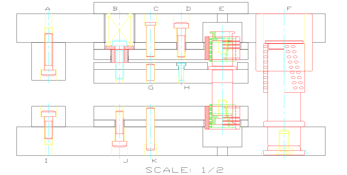
1. Mold Design Standard Structural Diagram
| No. | Standard Parts Diagram |
| A | Upper Limit High Pillar: Functions to ensure the precision of mold closure and prevent parts from being damaged. |
| B | Upper Mold Spring and Equi-height Sleeve: Functions to aid in ejecting the molded part |
| C | Upper Mold Pin: Functions to precisely fix and locate the upper mold base, upper bolster, and clamp plate. |
| D | Upper Mold Screw: Functions to secure the mold plate. |
| E | Misumi Inner Guide Post and Guide Sleeve: Functions to bear the precision of the entire set of mold components. |
| F | Misumi Outer Guide Post and Guide Sleeve: Functions to bear the precision of mold components and ensure alignment between upper and lower molds. |
| G | Ejector Pin: Functions to fix and position the fixed plate and ejector plate. |
| H | Ejector Screw: Functions to secure the mold plate. |
| I | Lower Limit High Pillar: Functions to ensure the precision of mold closure and prevent parts from being damaged. |
| J | Lower Mold Screw: Functions to secure the lower mold plate. |
| K | Lower Mold Pin: Functions to precisely fix and locate the lower mold base, lower bolster, and lower mold seat. |
2. Standard Specifications for the Layout of Material Strips in Mold Design
| No. | Layout Diagram |
| 1 | Holes with high positional tolerance requirements or those prone to breakage need to be punched simultaneously; as shown in figures 1/2. |
| 2 | If there are holes for bending or other processes with high positional accuracy requirements, punch them after bending. This can avoid inaccuracies in unfolding that may affect dimensions; as shown in figures 11/12 for bending, and figure 13 for cutting after bending. |
| 3 | In cases where there is symmetrical bending in the product, synchronous bending needs to be designed; as shown in figures 21/22/23. |
| 4 | Processes like stretching or others that may affect dimensions during forming need to be addressed in advance; as shown in figure 10 with stretching first, followed by forming in figures 15/16. |
| 5 | For variations in the production process, adjustments to parts need to be increased, reducing the need for maintenance of the lower mold during production; as shown in figure 19. |
3. Design Standards for Mold Components
Cutting Station Design Standards
- The drawing should specify the processing technology, where K represents fast cutting, M represents slow cutting, Y represents grinding, F represents discharge machining, X represents milling, PG represents wire cutting, and YG represents oil cutting. For precision blade drawings, the requirements are YG oil cutting – Y grinding – F discharge machining.
- Material selection for components, such as ASP23, ASP60, WC, DC53, SKD11, SKH-9, SKH-53. Different materials should be applied based on the characteristics of the plate. For cutting punches, ASP60 with an HRC of 62 degrees is prioritized.
- For soft materials with a thickness t < 1MM, the blade gap is c = (3%-4%) t; for t = 1MM-3MM, the blade gap is c = (5%-8%) t; for t = 3MM-5MM, the blade gap is c = (8%-10%) t.
- For hard materials with a thickness t < 1MM, the blade gap is c = (4%-5%) t; for t = 1MM-3MM, the blade gap is c = (6%-8%) t; for t = 3MM-8MM, the blade gap is c = (8%-13%) t.
- Try to avoid designing rectangular punches, as rectangular punches are prone to waste jumping.
- For blade widths less than 1.0mm (round holes less than 1.0mm in diameter), for easy processing and improved accuracy, the blades need to be processed separately.
- Punches should avoid excessively long and narrow grooves, and sharp corners should be avoided as much as possible. The length of small punches should be kept as short as possible, with appropriate reinforcement added.
- Punches should be designed with an anti-stripping structure, considering the reduction of discharge machining.
Design Standards for Forming Components
Standard for the fit clearance of forming punches, standard for the springback parameters of parts with R-angle bending, referring to the “Springback Value Table.” Depending on the hardness of the material, the greater the hardness, the larger the values can be.Springback Standard for R≤5 Bending
Material Thickness Bending Angle >90° <90° 90° Empty Stainless steel Phosphor/ Bronze/ Beryllium copper T<0.3mm 3°-5° 2°-4° 0.1-0.2° 5°-10° T>0.3mm 2°-4° 2°-3° 0.1-0.2° 4°-8° Iron material/ Bronze/Red copper T<0.3mm 1°-3° 2°-3° 0.1-0.2° 2°-4° T>0.3mm 1°-2° 1°-2° 0.1-0.2° 1°-3°
4. Template Block Design and Processing Standards
- Precision requirements for template processing: machining tolerances and special manufacturing processes.
- For template templates longer than 500mm, split design is required; all molds need to have process reference holes.
- The processing accuracy of mold template parts in the whole set is required to be controlled within ±0.01mm, and the surface roughness of the template is required to be less than 0.4um.
- For the blanking holes, stacking bodies, and oil cutting of the blanking plate and lower template, all fixed pin holes are treated with JG grinding; the sliding fit clearance C+ (0.005-0.010mm), non-sliding fit clearance C+0.003mm, machining accuracy ±0.002mm.
- For the upper template, blanking plate, and lower template, the use of Misumi internal guide pins and guide bushes filled with glue improves guiding accuracy to ensure the positional accuracy of the template during production.
- After heat treatment, the template undergoes super-deep cryogenic aging treatment, and some may require stabilization treatment to eliminate internal stress, prevent grinding deformation, and ensure template flatness of 0.005mm.
5. Mold Inspection Requirements
- Verify that punches, inserts, dimensions of template length, and thickness conform to the drawing specifications.
- Check the condition of screw holes and threading; assess the fit clearance of internal and external guide pillars; inspect for any missed wire cutting.
- Measure the thickness dimensions of the template, and a difference of within 0.005mm in four-point measurements is considered acceptable.
- Inspect the relinquishment processing status; ensure that the hole diameters and counterbore depths of various template through-holes comply with the drawing specifications.
- Examine whether each hole is eccentric, assess the alignment of templates, and check the normality of positioning pins.
- Apply chamfering to the periphery of the template. Include mold identification details on the sides, such as mold number, part number, material code, pitch, material width, mold closing height, and other parameters.
6. Mold Assembly Standards
- Mold assembly is divided into two parts, upper and lower, assembled separately, and finally, the upper and lower molds are assembled together.
- Firstly, understand the mold drawings, product information, analyze the mold structure, and comprehend the design intent of the mold.
- Chamfer, polish, engrave, and categorize the templates and parts.
- Use specialized positioning tools for installing internal and external guide pins and bushings to ensure their verticality during the positioning and gluing process.
- Ensure smooth assembly of punches and block pairs, and appropriate force when tapping parts.
7. Mold Spare Parts Detailed Management
For molds accommodating multiple machine types, each part is assigned a unique number for clear and separate storage. This facilitates efficient replacement during the production process, expedites effective mold assembly, and reduces downtime during the production line changeover.
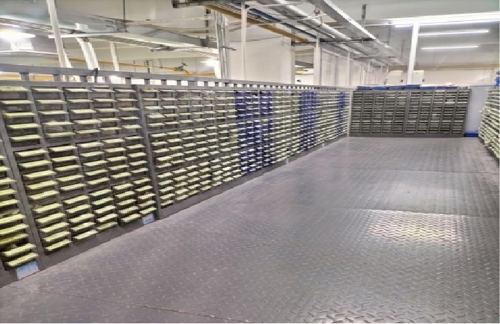

Figure 1: Spare Part Temporary Storage Area
Parts are systematically arranged for easy visibility and subdivided into spare parts, blade components, machine-specific parts, molding parts, and standard components.
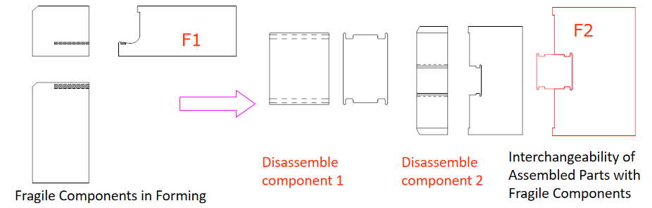
8. Continuously Optimize Part Structures, Validated Parts as Design Standards
Emphasizing technological innovation in designing parts: Figure 1 depicts a symmetric part that, once subjected to bending wear during the production process, becomes unusable. In Figure 2, a design optimization involves disassembling the part and redesigning the bending position as a double-sided molded part. Wear can be mitigated by turning to the other side for forming, effectively reducing processing costs and production downtime.
Conclusion:
In the dynamic landscape of metal stamping, the standardization of molds emerges as a cornerstone for operational excellence. It not only ensures the reliable production of high-quality parts but also positions manufacturers to adapt swiftly to industry advancements. As technology continues to reshape the manufacturing landscape, the role of standardized metal stamping molds becomes increasingly critical in driving efficiency, precision, and overall competitiveness.