Tag Archive for: BESS connector

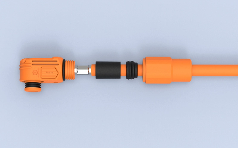
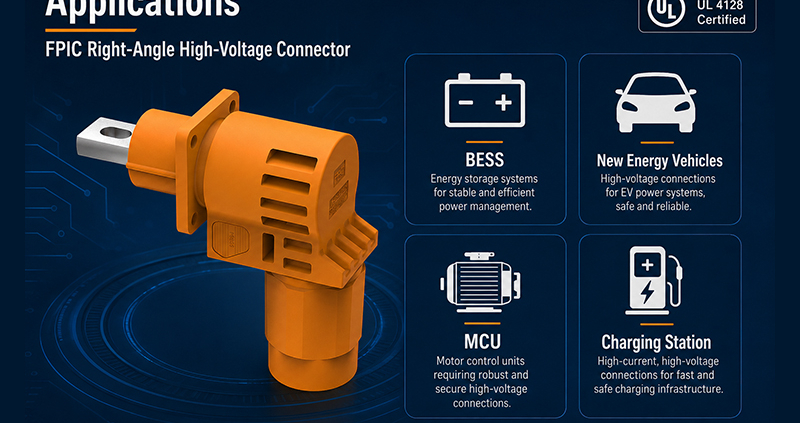
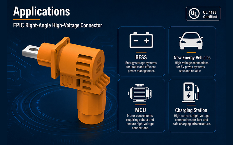
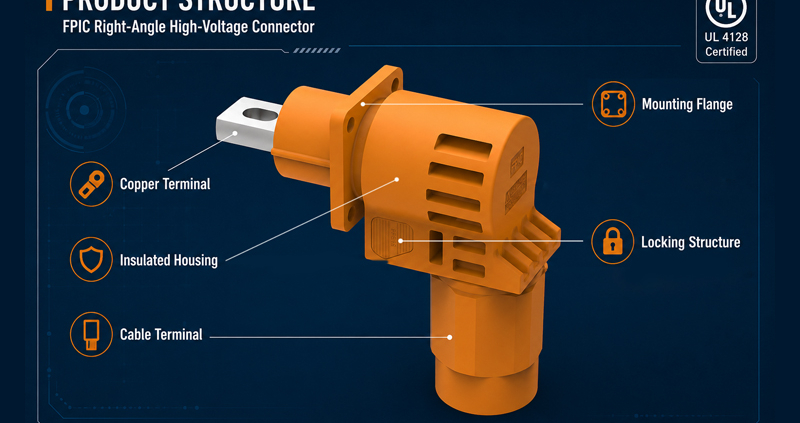
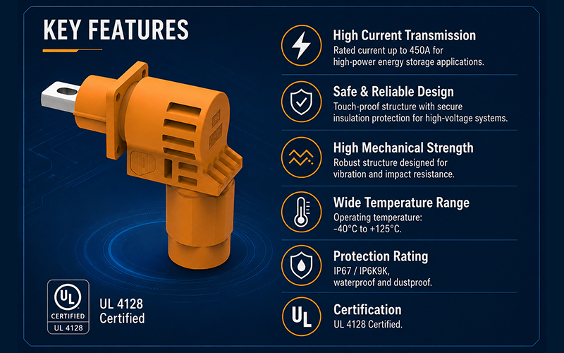
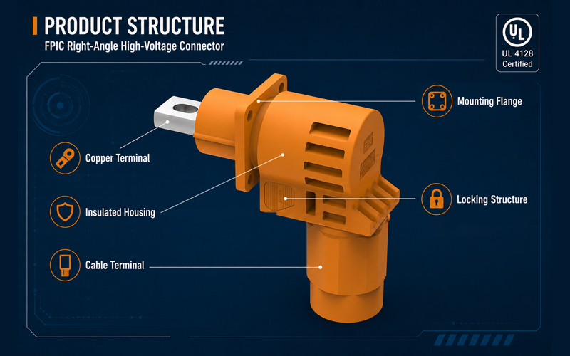
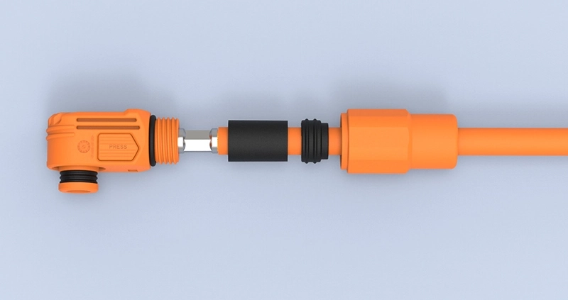
FPIC 2000V 450A connector for BESS battery interconnection

Battery energy storage systems are moving toward higher power density, larger blocks, and more demanding DC architectures. For next-generation BESS, 2000V connectors can support a platform that transmits the same power at lower current than a 1500V design, creating opportunities to reduce resistive loss, simplify parallel current paths, or increase power capacity within a defined system envelope.

That benefit is not automatic. Raising the DC voltage also increases the demands placed on insulation coordination, connector geometry, cable construction, switching protection, assembly control, and system-level validation. A 2000V-rated connection only delivers value when the battery, busbars, cables, fuses, contactors, power conversion system, enclosure, and service procedures are engineered for the same voltage class.

Direct answer: At the same transmitted power, increasing the DC voltage from 1500V to 2000V reduces current by 25%. If the total path resistance remains unchanged, the calculated resistive loss falls by 43.75%. Actual BESS performance still depends on the complete electrical and thermal design.


2000V Is a System Architecture, Not Just a Connector Rating

Recent product roadmaps show that the 2000V class is becoming a practical development direction across high-voltage energy systems. In June 2026, CATL stated that its TENER Sodium energy storage platform reserves an upgrade path to a 2000V architecture. Amphenol’s TS1 connector platform, introduced in December 2025 for high-power electrification applications including energy storage, supports up to 2000V and 450A in selected configurations. Amphenol also expanded its photovoltaic connector platform to 2000V in August 2026 for high-voltage PV and solar-plus-storage architectures.

These developments do not mean that every new BESS should immediately move beyond 1500V. They show that battery, power-electronics, cable, protection, and connector suppliers are preparing for a higher-voltage ecosystem. Whether the change makes commercial sense depends on the system topology, maximum operating voltage, power level, cooling strategy, certification route, installation conditions, and balance-of-system cost.

For engineering and procurement teams, the correct question is therefore not simply, “Is 2000V better?” It is, “Does a higher-voltage architecture improve this system after every affected component and risk is included?”

What Changes Electrically from 1500V to 2000V?

For a DC power path, the basic relationship is:

Power = Voltage × Current

If power remains constant, increasing voltage reduces the current required. The following comparison uses an ideal 1 MW DC transfer point.

Parameter1500V Architecture2000V Architecture
DC power1 MW1 MW
Calculated current666.7A500A
Current relative to 1500V100%75%
Relative (I^2R) loss at the same resistance100%56.25%

This calculation shows two important points. First, the current reduction is 25%, not one-third. Second, because conductor and contact loss follows (P_{loss}=I^2R), the theoretical resistive loss falls faster than the current—provided the resistance is genuinely unchanged.

Real systems are more complicated. Converter efficiency, busbar geometry, cable length, conductor cross-section, connector contact resistance, ambient temperature, enclosure airflow, and duty cycle all affect the final result. Higher voltage can reduce current-related loss, but it does not eliminate conversion losses or thermal constraints elsewhere in the BESS.

At a fixed current, a 2000V path can also transmit 33.3% more power than a 1500V path. That may support higher power density, but only when the connector, conductor, protection devices, and cooling system remain within their verified limits.
FPIC 2000V 450A connector for BESS battery interconnection

Does Higher Voltage Allow a Smaller Cable?

Potentially, but cable cross-section should never be selected from voltage and power alone.

A lower operating current may allow engineers to reduce conductor area or the number of parallel paths. The final cable decision must still account for:

  • continuous current and peak-current duration;
  • allowable conductor and terminal temperature;
  • insulation voltage and temperature rating;
  • ambient temperature and enclosure cooling;
  • cable grouping and installation method;
  • voltage drop and total path length;
  • bend radius, routing space, and mechanical stress;
  • applicable derating and end-equipment requirements.

A higher-voltage cable may require different insulation construction, wall thickness, jacket material, or spacing. As a result, a 25% current reduction does not automatically translate into a 25% reduction in cable size, copper use, or installed cost.

The connector and cable must also be evaluated as a matched termination system. A large conductor cannot compensate for a poorly controlled crimp, unstable contact interface, or unsuitable thermal path.


Why Insulation Design Becomes More Demanding

The move to a higher DC voltage changes more than the printed rating on the housing. It affects the physical distances, insulating materials, environmental assumptions, and protective measures used throughout the connection.

Clearance

Clearance is the shortest distance through air between conductive parts. The required value is influenced by working voltage, transient overvoltage, altitude, and the applicable insulation-coordination rules. Air has lower dielectric strength at higher altitude, so a connection that works at one installation elevation may require additional spacing or evaluation at another.

Creepage Distance

Creepage is the shortest path along the surface of an insulating material. It is affected by working voltage, pollution degree, condensation risk, surface geometry, and the material’s resistance to tracking. Dust, moisture, salt, and process contamination can turn an apparently clean surface into a more conductive path.

Solid Insulation and Material Selection

Housing materials must be evaluated for electrical, thermal, mechanical, and flammability requirements relevant to the product. Comparative tracking index can support material grouping, but it does not by itself establish a safe creepage distance. Wall thickness, molded features, material aging, and manufacturing consistency also matter.

IEC 60664-1 provides widely used principles for clearance, creepage, solid insulation, pollution degree, altitude, and overvoltage assessment. Its stated scope covers equipment up to 1500V DC, however. A 2000V design therefore requires the applicable product and end-equipment requirements, together with guidance from the responsible certification body; simply extending a 1500V spacing table is not a sufficient validation method.


Contact Resistance and Temperature Rise Still Control Current Capability

Higher system voltage can reduce current for a fixed power target, but it does not make contact resistance less important. Heat generated at a connection follows the same (I^2R) relationship as cable loss.

Consider an illustrative contact-interface resistance of 0.1 mΩ. At 450A, that interface would dissipate approximately 20.25W:

450A × 450A × 0.0001Ω = 20.25W

This example is not an FPIC product specification. It shows why a small change in resistance can create meaningful heat at high current.

Contact resistance can be influenced by terminal geometry, contact force, plating system, surface condition, crimp quality, conductor preparation, mating alignment, vibration, thermal cycling, and long-term stress relaxation. Temperature-rise testing should therefore use the intended conductor, termination process, ambient condition, enclosure arrangement, mounting orientation, and load profile. A current rating should not be treated as independent of those conditions.

For a deeper thermal-design discussion, see How Temperature Rise Affects High-Current Connectors.

What Should Be Verified for a 2000V BESS Connection?

UL 4128 is an important North American reference for intercell and intertier connectors used in electrochemical battery systems. The current scope covers cable connectors, cable, and mating inlets rated up to 3000V DC, and it states that these devices are not intended to be connected or disconnected under load.

The final verification plan must follow the applicable standard and end-use application. For a high-voltage battery interconnection, engineering teams should normally establish evidence for the following areas:

Verification areaQuestion to answerTypical evidence
Voltage ratingCan the complete mated interface withstand the defined working voltage and overvoltage conditions?Insulation design review, dielectric test, certification report
Insulation resistanceDoes electrical isolation remain acceptable before and after relevant conditioning?Insulation-resistance results under specified conditions
Thermal performanceDoes the interface stay within material and conductor temperature limits at the intended load?Temperature-rise test using the defined cable, ambient, and duty cycle
Contact stabilityDoes resistance remain controlled after mechanical and environmental stresses?Initial and post-conditioning resistance measurements
Termination qualityCan the cable, crimp, or busbar interface withstand assembly and service loads?Cross-section review, crimp records, pull or mechanical retention tests
Mating safetyAre polarity, keying, locking, and touch-protection measures suitable for the equipment design?Dimensional inspection and functional verification
EnvironmentWill humidity, contamination, vibration, thermal cycling, and ingress affect performance?Application-specific environmental tests; IP testing only when claimed
End-use integrationIs the recognized component acceptable inside the complete BESS?Conditions-of-acceptability review and system-level evaluation

A component certificate is valuable evidence, but it is not a substitute for complete-system certification. UL explains that UL 9540 evaluates the energy storage system as an assembly, including charging, discharging, protection, controls, communications, and interaction among devices.


What FPIC’s 2000V 450A UL Recognition Covers

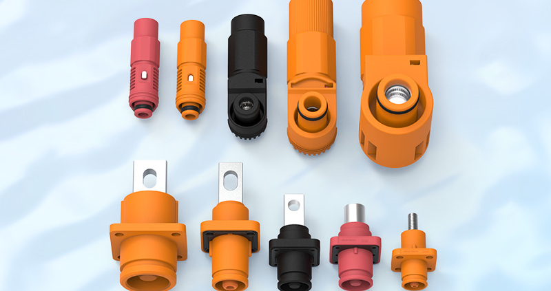
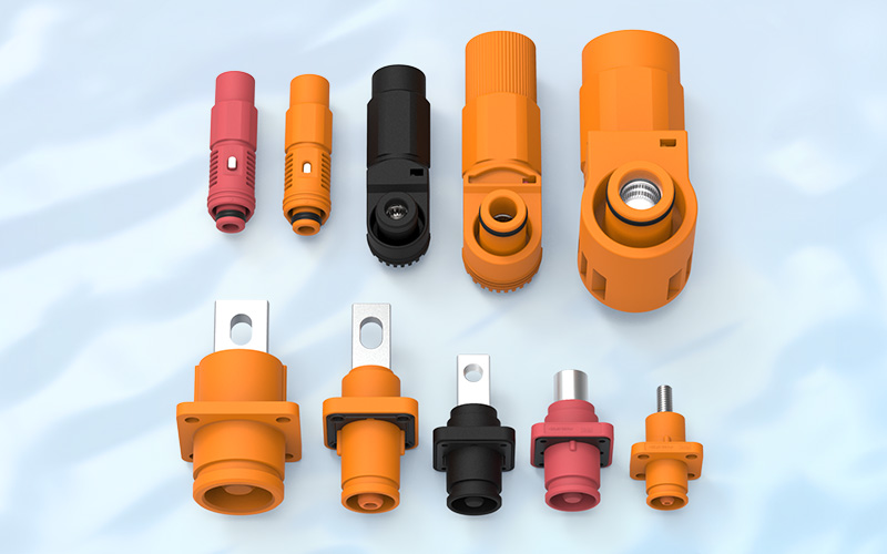
Representative samples of FPIC’s energy storage connector series were evaluated by UL to UL 4128 for electrochemical battery system applications. The UL documentation identifies the series under category BBTH2, with certificate number UL-US-26118764-0 and report reference E533832-20260524, issued on May 25, 2026.

The evaluated series includes insulated, single-pole cable connectors and panel-mounted inlets rated 2000V DC and 450A. For the cable-connector configuration, the evaluated conductor size is 300 kcmil. The panel-mounted versions are intended for factory assembly to suitable copper conductors or copper/copper-alloy busbars in battery equipment.

  • The scope and limitations are equally important:
  • the products are UL Recognized Components, not complete end-use equipment;
  • they are not suitable for disconnecting under load;
  • the evaluated products are intended for use within complete equipment;
  • the FPIC report states that they were not investigated for an environmental rating or for use outside an equipment enclosure;
  • acceptability must be determined in the final application.

This recognition gives BESS engineers a verified component-level reference for a 2000V, 450A intercell/intertier connection. It should not be interpreted as blanket approval for every cable, enclosure, ambient condition, or storage-system design.


A Practical Checklist Before Specifying the Connection

Before requesting a sample or quotation, define the actual operating envelope rather than providing only a voltage and current target. FPIC’s separate guide on selecting a 2000V 450A BESS connector provides additional product-screening questions.

  1. Electrical requirements: nominal voltage, maximum continuous DC voltage, transient conditions, continuous current, peak current, and duty cycle.
  2. Conductor interface: cable size and construction, busbar material and thickness, terminal temperature rating, and preferred termination method.
  3. Thermal environment: cabinet ambient temperature, cooling method, neighboring heat sources, mounting orientation, and allowable temperature rise.
  4. Installation conditions: indoor or outdoor location, enclosure protection, altitude, pollution, condensation, chemical exposure, vibration, and shock.
  5. Safety functions: polarity, mechanical keying, touch protection, locking, service isolation, and any high-voltage interlock requirement.
  6. Compliance route: target country, component standard, end-equipment standard, marking requirement, and certification-body expectations.
  7. Project inputs: drawings, 2D/3D files, cable specifications, mating layout, samples, forecast volume, and development schedule.

This information allows the connector, cable, termination, and installation method to be reviewed together. It also prevents a nominal rating from being applied outside the configuration in which it was verified.


Conclusion: 2000V Creates an Opportunity—and a Higher Design Burden

The main advantage of a 2000V BESS architecture is straightforward: more power can be transmitted with less current, or more power can be carried at the same current. This can reduce current-related losses and may simplify some conductor paths.

The engineering burden rises at the same time. Insulation coordination, creepage and clearance, material behavior, contact resistance, cable matching, service procedures, protection devices, and complete-system validation all require closer control.

FPIC’s 2000V 450A UL Recognized connector series provides a verified component option for defined electrochemical battery equipment applications. Explore FPIC’s broader energy storage connector range or request a custom connector evaluation using your maximum operating voltage, load profile, cable or busbar details, installation environment, drawings, and target compliance requirements.

Discuss your BESS interconnection project: info@fpiconn.com


FAQ

1.Does a 2000V architecture automatically make a BESS more efficient?

No. Higher voltage reduces current at the same power, which can lower resistive losses, but actual efficiency also depends on the PCS, conductors, connectors, cooling, topology, and operating profile.

2.How much does current decrease when moving from 1500V to 2000V?

Current decreases by 25% at the same power. For an ideal 1 MW DC path, current changes from approximately 666.7A at 1500V to 500A at 2000V.

3.Can a 1500V connector be used in a 2000V battery system?

No. A connection is limited by its lowest-rated component. The connector, cable, protection devices, busbars, and related equipment must all be suitable for the system’s maximum voltage and applicable transient conditions.

4.Does a 450A rating apply to every cable size and ambient temperature?

No. Current capability depends on the evaluated conductor, termination, ambient temperature, enclosure, cooling, duty cycle, and applicable derating. FPIC’s UL-evaluated cable-connector configuration uses a 300 kcmil conductor.

5.Is UL 4128 recognition the same as certification of a complete BESS?

No. UL 4128 addresses the defined intercell/intertier connector component. The complete energy storage system must be evaluated under the applicable end-equipment and installation requirements.

6.Can the FPIC connector be disconnected while current is flowing?

No. The UL documentation states that the recognized connector is not suitable for disconnecting under load. The equipment must provide an appropriate isolation and service procedure.


Resources

  1. CATL: TENER Sodium Energy Storage System and 2000V Upgrade Path, June 22, 2026.
  2. Amphenol Industrial Operations: TS1 High-Voltage, High-Current Connector, December 2025.
  3. Amphenol Industrial Operations: H4 Plus P2KV 2000V Expansion, August 20, 2026.
  4. IEC 60664-1:2020 — Insulation Coordination for Low-Voltage Supply Systems, including Amendment 1:2025.
  5. UL Standards & Engagement: UL 4128, Edition 6, published June 16, 2026.
  6. UL Solutions: Energy Storage System Testing and UL 9540 Certification.
How Temperature Rise Affects High-Current Connectors

High-current connector selection often starts with one number: the rated current.

A customer may see “450A” on a product specification and reasonably assume that the connector can continuously carry 450A in any equipment environment.

That assumption can be dangerous.

Quick Answer:

Temperature rise in a high-current connector depends on current, contact resistance, conductor size, terminal design, material, ambient temperature, installation conditions, and heat dissipation. A 450A rating only applies under defined test conditions; actual continuous current may need to be reduced when ambient temperature or thermal loading increases.

That is why high-current connector engineering should focus not only on current rating, but also on thermal performance under real operating conditions.


Why High-Current Connectors Generate Heat

Every electrical connection has resistance.

Even when that resistance is very small, current passing through the interface generates heat.

The basic relationship is:

Power loss = I² × R

This is one of the most important relationships in high-current connector design.

If current doubles while resistance remains unchanged, the heat generated by resistive losses increases by a factor of four.

That means a resistance change that seems insignificant at 10A may become important at 300A or 450A.

For example, heat can develop at:

  • contact interfaces;
  • crimp connections;
  • busbar interfaces;
  • conductor transitions;
  • cable terminals;
  • bolted connections.

The goal is therefore not simply to achieve low resistance at the initial test.

The contact system must maintain low and stable resistance throughout its service life.


Contact Resistance Is One of the Main Heat Sources

Contact resistance is created where two conductive surfaces touch.

In a high-current connector, this usually occurs between the plug and receptacle terminals.

The resistance depends on several factors:

  • contact geometry;
  • effective contact area;
  • normal contact force;
  • surface roughness;
  • terminal material;
  • plating material;
  • contamination;
  • wear;
  • corrosion;
  • mating cycles.

A well-designed terminal provides sufficient contact pressure to maintain a stable conductive path.

If contact pressure becomes too low, resistance may rise.

This can lead to:

Higher resistance → More heat → Faster material degradation → Even higher resistance

That cycle can become a long-term reliability risk.

TE describes low contact resistance as one reason its high-power connector designs can reduce temperature rise and power loss. Molex similarly links low contact resistance with lower voltage drop and lower heat generation in its high-current COEUR-based interconnects.


Terminal Material Influences Thermal Performance

How Temperature Rise Affects High-Current Connectors

Terminal material must provide both electrical conductivity and mechanical stability.

Typical high-current connector contacts use copper or copper-alloy materials.

Pure copper offers excellent conductivity, but connector terminals also require mechanical properties such as:

  • strength;
  • spring stability;
  • formability;
  • fatigue resistance;
  • resistance to stress relaxation.

Depending on the terminal structure, manufacturers may therefore use different copper alloys to balance conductivity and mechanical performance.

Common options include:

  • high-conductivity copper;
  • brass;
  • phosphor bronze;
  • copper-nickel-silicon alloys;
  • other high-conductivity copper alloys.

FPIC’s internal connector materials identify alloys such as C7025, C7035, and C18400 as suitable options for higher-current applications because they provide a useful combination of conductivity and mechanical properties.

Material choice should therefore be based on both electrical and mechanical requirements.


Plating Also Affects Contact Stability

The base terminal material is only one part of the contact system.

The contact surface may use plating such as:

  • tin;
  • silver;
  • gold;
  • nickel underlayers.

For high-current power applications, silver plating is commonly used because of its conductivity and contact performance.

Tin can also be suitable in many applications, although friction, fretting, oxidation, temperature, and mating-cycle requirements must be considered.

The plating system affects:

  • contact resistance;
  • corrosion resistance;
  • wear;
  • friction;
  • temperature stability;
  • service life.

The correct plating is therefore determined by the application rather than by choosing the most expensive material.


Cable Cross-Section Directly Affects Temperature Rise

A connector cannot be evaluated independently from its cable.

The resistance of a conductor depends on:

Material resistivity × conductor length ÷ conductor cross-sectional area

In practical terms:

A smaller conductor generally has greater resistance and produces more heat under the same current.

This is why connector specifications normally define compatible cable sizes.

For example, a high-current interface might be designed around conductor sizes such as:

  • 35 mm²;
  • 50 mm²;
  • 70 mm²;
  • 95 mm²;
  • 120 mm²;
  • 150 mm².

The cable cross-section must match both:

  1. the required current capacity; and
  2. the terminal crimp or termination design.

Phoenix Contact provides a useful example: the same connector can have different permissible currents depending on whether it is used with 2.5 mm², 4 mm², or 6 mm² conductors. Its published derating example shows that conductor size and ambient temperature both materially change the usable current.


Crimp Quality Can Become a Hidden Heat Source

Even when the connector and cable are correctly sized, poor termination can create additional resistance.

For a crimped connection, engineers must control:

  • crimp height;
  • crimp width;
  • conductor position;
  • conductor compression;
  • strand damage;
  • bellmouth;
  • terminal deformation;
  • pull-out force.

A poor crimp can create:

  • insufficient conductor contact;
  • uneven current distribution;
  • localized resistance;
  • localized heating.

FPIC’s terminal crimping standards therefore treat crimp height as one of the most important production controls and also use pull-force and cross-section analysis to verify termination quality.

For high-current connectors, termination quality is part of thermal management.


Ambient Temperature Changes the Available Thermal Margin

Connector temperature is not determined by self-heating alone.

The final operating temperature is approximately influenced by:

Ambient temperature + temperature rise caused by current

This means the same connector may behave differently in:

  • a 25°C laboratory;
  • a 40°C industrial cabinet;
  • a 55°C BESS cabinet;
  • an outdoor enclosure exposed to solar heating.

If a connector housing or cable insulation has a maximum permitted operating temperature, higher ambient temperature leaves less room for self-heating.

Phoenix Contact describes current-carrying capacity as dependent on both self-heating and ambient temperature, and its derating curves show permissible current decreasing as ambient temperature rises.

This is why high-current connector selection should include a current-temperature derating curve, not only one headline ampere value.


Continuous Current Is More Important Than Short Peak Current

A connector may experience several types of current:

  • continuous operating current;
  • short peak current;
  • startup current;
  • overload current;
  • pulse current.

These loads do not create the same thermal effect.

A short-duration peak may not allow enough time for the complete connector assembly to reach thermal equilibrium.

Continuous current is different.

When current flows for a long period, the connector continues heating until the generated heat and dissipated heat reach equilibrium.

For BESS applications, this distinction is particularly important because energy storage systems can operate under sustained charging or discharging conditions.

Therefore, the engineering question should not only be:

What is the maximum current?

It should also be:

How long will that current flow?


Why “Rated 450A” Does Not Mean 450A Everywhere

This is the most important point of the article.

A current rating is normally determined under specified test conditions.

Those conditions can include:

  • ambient temperature;
  • conductor size;
  • conductor length;
  • contact configuration;
  • mounting arrangement;
  • temperature-rise limit;
  • airflow;
  • measurement location.

TE explicitly states that its published current ratings represent maximum continuous current under defined or optimum conditions and that derating factors must be applied for higher ambient temperature and multiple loaded circuits.

IEC 60512-5-1 defines a standardized method for evaluating connector temperature rise under current load, while IEC 60512-5-2 addresses current-temperature derating at elevated ambient temperatures.

Therefore:

450A means:

The connector has demonstrated a defined current-carrying capability under specified conditions.

It does not mean:

The connector can operate continuously at 450A in every enclosure, cable configuration, temperature, altitude, or cooling condition.

That distinction should always be explained clearly to customers.


Multiple Loaded Contacts Can Change Current Capacity

For multi-contact connectors, another factor appears: mutual heating.

When multiple adjacent contacts carry current simultaneously, each contact contributes heat to the connector housing.

This raises the internal temperature and can reduce the current that each contact can safely carry.

TE notes that the current capacity per contact decreases when multiple contacts are simultaneously used for power transmission.

This means engineers must define:

  • how many contacts carry current;
  • current per contact;
  • spacing between contacts;
  • conductor sizes;
  • enclosure temperature.

A single-contact rating cannot simply be multiplied by the number of contacts.


Connector Housing Material Sets Another Thermal Limit

The terminal is not the only component exposed to heat.

The housing, seals, cable insulation, and nearby materials also have temperature limits.

Typical connector housing materials include:

  • PA66;
  • PBT;
  • LCP;
  • PA6T;
  • PA9T;
  • PPS.

Different polymers provide different:

  • heat resistance;
  • mechanical strength;
  • moisture absorption;
  • dimensional stability;
  • flame performance.

FPIC’s internal engineering materials identify high-temperature materials such as LCP, PA9T, PA6T, PA46, and PPS for connector designs that must withstand elevated-temperature processes such as reflow soldering.

The thermal limit of the complete system should therefore reflect the lowest critical material limit, not only the copper contact.


High-Voltage BESS Cabinets Create More Difficult Thermal Conditions

Energy storage systems are a particularly relevant example.

Inside a BESS cabinet, multiple heat sources may exist:

  • battery modules;
  • busbars;
  • contactors;
  • fuses;
  • high-current connectors;
  • power conversion equipment;
  • cable bundles.

The cabinet itself may also have restricted airflow.

This means the connector operates within a larger thermal system.

Engineers must consider:

  • cabinet ambient temperature;
  • cable bundle temperature;
  • neighboring components;
  • ventilation;
  • cooling system design;
  • continuous charge/discharge profile.

For this reason, the connector temperature should ideally be evaluated inside a representative system environment rather than only through a catalog value.


Temperature Rise Testing Provides the Evidence

Temperature-rise testing helps determine how much the connector heats when current passes through it.

A typical test process includes:

  1. assemble the connector with the specified conductor;
  2. place temperature sensors at defined measurement points;
  3. record initial ambient and component temperature;
  4. apply the test current;
  5. wait until thermal equilibrium;
  6. record the maximum temperature;
  7. calculate the temperature rise;
  8. repeat at different current levels if required.

IEC 60512-5-1 specifically defines a test method for assessing current-carrying capability based on connector temperature rise.

The resulting data can then help generate a current-temperature derating curve.


What FPIC Tests During High-Current Validation

FPIC has dedicated equipment for connector electrical and thermal validation.

Our internal laboratory capability includes:

  • temperature-rise testers;
  • contact-impedance testers;
  • withstand-voltage testers;
  • insulation-resistance testing;
  • insertion and extraction force testing;
  • vibration testing;
  • thermal-shock chambers;
  • X-ray inspection;
  • dimensional inspection.

FPIC’s equipment list includes multiple temperature-rise testers and contact-impedance instruments, supporting validation of high-current connector and cable-assembly performance.

For high-current projects, the validation plan can evaluate:

  • connector temperature rise;
  • terminal resistance;
  • cable temperature;
  • crimp condition;
  • interface stability;
  • mechanical reliability.

Applying This to FPIC’s 2000V 450A Connector

FPIC’s high-current energy storage connector portfolio includes 2000V / 450A solutions for battery-system applications.

But the correct engineering message is not:

450A can always be used continuously.

The more technically credible message is:

The 450A platform is designed and validated for high-current energy storage applications under defined conditions, and final current capability should be confirmed against conductor size, ambient temperature, installation environment, and system thermal requirements.

This distinction strengthens rather than weakens the product story.

It tells engineers that FPIC understands how current ratings actually work.

For BESS customers, FPIC can support project evaluation based on:

  • system voltage;
  • continuous and peak current;
  • cable cross-section;
  • connector mounting;
  • ambient temperature;
  • cabinet cooling;
  • duty cycle;
  • required temperature-rise limit.

This moves the discussion from catalog selling to engineering selection support.


High-Current Connector and Cable Assembly Must Be Evaluated Together

For high-current systems, the connector and cable assembly form one electrical and thermal path.

The evaluation should include:

ComponentKey thermal factors
ContactMaterial, geometry, resistance, plating
TerminalCrimp structure and conductor interface
CableCross-section, material, length, insulation
Connector housingTemperature capability and heat dissipation
Busbar interfaceSurface area, contact pressure, resistance
CabinetAmbient temperature and airflow
LoadContinuous current, peak current, duty cycle

Ignoring any one of these factors can produce an incomplete thermal assessment.


A Practical High-Current Connector Selection Checklist

Before selecting a high-current connector, provide the following data:

Electrical Requirements

  • nominal voltage;
  • maximum voltage;
  • continuous current;
  • peak current;
  • peak duration;
  • duty cycle.

Cable Requirements

  • conductor material;
  • conductor cross-section;
  • cable outer diameter;
  • insulation temperature rating.

Thermal Environment

  • minimum and maximum ambient temperature;
  • enclosure temperature;
  • airflow;
  • cooling method;
  • nearby heat sources.

Mechanical Installation

  • panel mount or cable mount;
  • busbar connection;
  • cable orientation;
  • available space.

Validation Requirements

  • permitted temperature rise;
  • test current;
  • test duration;
  • applicable IEC, UL, or customer standards.

Providing this information allows engineers to evaluate the real usable current, not simply repeat the catalog rating.


Frequently Asked Questions

1. What causes temperature rise in a connector?

Temperature rise primarily comes from electrical resistance in contacts, terminals, crimps, conductors, and interfaces while current is flowing.

2. Does lower contact resistance reduce temperature rise?

Generally yes. Lower resistance reduces resistive power loss at a given current, assuming the rest of the thermal system remains unchanged.

3. Does a larger cable always reduce connector temperature?

A larger conductor usually reduces cable resistance and can improve heat conduction away from the interface, but connector geometry, terminal design, ambient temperature, and installation conditions must still be evaluated.

4. Can a 450A connector continuously carry 450A?

Only under the conditions for which the current rating has been established. Higher ambient temperature, different conductor sizes, restricted cooling, or other installation factors may require derating.

5. Why is temperature-rise testing important?

It verifies how the complete connector assembly behaves under current load and helps determine whether the contact, terminal, housing, and cable remain within permitted temperature limits.

6. What is a connector derating curve?

A derating curve shows how permissible current decreases as ambient temperature increases. It provides a more realistic selection tool than a single rated-current number.


Conclusion

Current rating alone does not define high-current connector performance.

Temperature rise depends on the complete electrical and thermal system:

current + resistance + conductor + material + ambient temperature + installation + duty cycle

For BESS and other high-power systems, this is why a 450A connector should be evaluated as part of the complete application rather than treated as an isolated 450A component.

FPIC supports high-current connector and cable-assembly projects with connector development, conductor and terminal matching, temperature-rise testing, contact-resistance measurement, prototype validation, and repeat-production quality control.

Discuss Your High-Current Connector Project

FPIC supports high-voltage and high-current interconnection development for BESS, battery systems, industrial equipment, and customized power applications.

Send us your voltage, current profile, cable specification, ambient temperature, installation method, and project drawings for engineering evaluation.

Email: info@fpiconn.com


Resources

  1. IEC. IEC 60512-5-1:2002 – Connectors for Electronic Equipment – Current-Carrying Capacity Tests – Temperature Rise.
  2. IEC. IEC 60512-5-2:2002 – Connectors for Electronic Equipment – Current-Temperature Derating.
  3. TE Connectivity. Battery Pack Connectors – Current Carrying Capacity, T-Rise and Derating.
  4. TE Connectivity. Power Connectivity – Current Rating and Derating Guidance.
  5. Phoenix Contact. Electrical Tests for Connectors – Current Carrying Capacity and Derating.
  6. Molex. SW1 High-Current Interconnects and COEUR Socket Technology.
Select High-Voltage Connectors for BESS Cabinets

BESS cabinets are getting more powerful, more compact, and more demanding. That is changing the way engineers and sourcing teams evaluate high-voltage connectors. What used to be treated as a simple power connection is now part of a broader discussion about safety, thermal stability, installation efficiency, and long-term operating risk.

If you are selecting connectors for a battery energy storage cabinet, the right question is no longer just “What voltage and current do I need?” A better question is “Which connector platform helps the cabinet operate more safely, integrate more cleanly, and remain easier to build and maintain over time?”

Why Connector Selection in BESS Cabinets Is Becoming More Strategic

A BESS cabinet is not just a box full of batteries. It is a system-level power architecture that must manage electrical load, temperature, mechanical layout, installation logic, maintenance access, and compliance expectations at the same time.

Inside that architecture, the connector sits in a critical position. It can link battery modules, racks, busbars, cabinet-level power paths, and distribution interfaces. That means connector selection affects much more than the simple ability to pass current.

A poorly chosen connector can create avoidable problems such as:

  • excess temperature rise at the interface
  • difficult routing in compact cabinet layouts
  • inconsistent installation on the production floor
  • polarity or mating mistakes during assembly or service
  • poor maintenance access during replacement
  • lower long-term reliability under real operating conditions

By contrast, a well-selected high-voltage connector helps make the cabinet safer, cleaner to integrate, and easier to manage over the full system lifecycle.

Start with the Real Application, Not Just the Catalog Spec

One of the most common mistakes in connector selection is to begin and end with rated voltage and rated current. Those values matter, but they do not tell the full story.

In BESS cabinet design, you should first define the real application environment:

1. Where is the connector used in the system?

A connector used for a battery rack interface does not always face the same requirements as one used for an internal cabinet power path or a service interface.

2. What load conditions will it actually see?

A catalog rating may look sufficient, but the real question is whether the connector can support the required current with stable contact behavior and acceptable temperature rise in the actual cabinet environment.

3. How will the connector be installed and serviced?

If the design requires fast, repeatable installation or easier field replacement, connector structure becomes just as important as electrical performance.

Selection becomes much easier when you treat the connector as a system interface rather than a standalone part.

Safety Should Be the First Screening Standard

In a high-voltage BESS cabinet, safety is not a secondary attribute. It is a first-level filter.

When reviewing connector options, teams should evaluate whether the design supports safer installation and operation in real conditions.

1. Touch-Proof Structure

Touch-proof design helps reduce the risk of accidental contact with energized conductive points. This is especially valuable during cabinet assembly, maintenance, and replacement operations.

2. Polarity Clarity and Anti-Misplug Design

In modular energy storage systems, polarity mistakes create unnecessary risk. Mechanical keying, coding, and clear positive/negative differentiation can help reduce installation errors.

3. Secure Mating Logic

A connector should provide stable electrical and mechanical engagement. Secure mating improves confidence during assembly and helps maintain contact stability during operation.

4. Application-Appropriate Compliance Direction

Many customers now consider compliance readiness earlier in the design cycle. Even when the final certification belongs to the complete system, connector selection still affects the path toward safer and more credible product integration.

Current Rating Must Be Evaluated Together with Thermal Performance

Current rating is still a basic selection parameter, but in BESS cabinets it should always be considered together with thermal performance.

Why? Because a connector that carries current on paper can still become a weak point in the cabinet if contact resistance is unstable or if heat builds up in a tight installation space.

That is why engineers should evaluate:

  • rated current
  • conductor compatibility
  • contact resistance stability
  • termination method
  • expected temperature rise
  • real cabinet airflow and space constraints

This is where high-current connector design becomes more than a numbers exercise. It becomes a thermal and reliability decision.

Installation Efficiency Matters More Than Many Teams Expect

In large-scale BESS deployment, installation speed and consistency matter. Connector design directly affects both.

A connector that supports a cleaner mating process, better cable routing, and clearer installation logic can help reduce:

  • assembly time
  • operator error
  • rework risk
  • field service time later

This is why the market is paying more attention to connector systems that improve installation, not only electrical transfer.

For BESS cabinet builders, connection efficiency can influence both production cost and long-term service experience.

Do Not Ignore Serviceability and Maintenance Access

BESS systems are long-life assets. That means maintainability should be part of connector selection from the beginning.

A connector that is difficult to reach, hard to disconnect, or easy to reconnect incorrectly may create future service cost even if it performs acceptably on day one.

Good high-voltage connector selection should therefore consider:

  • access during inspection
  • clarity during remating
  • replacement convenience
  • compatibility with modular cabinet design

In practice, the best connector is often the one that supports both stable operation and more predictable service work.

What to Look for in a High-Voltage Connector for BESS Cabinets

A practical selection checklist usually includes the following questions:

  • 1. Is the voltage platform aligned with the target system?

The connector should fit the actual platform requirement, whether the project is centered on 1000V, 1500V, or higher-voltage development.

  •  2. Is the current rating suitable for real cabinet conditions?

Do not treat rated current as an isolated number. Confirm the connector matches the true load path and thermal expectations.

  • 3. Does the structure support safer use?

Look for features such as touch-proof protection, mechanical keying, polarity control, and stable locking.

  • 4. Does it integrate well into the cabinet design?

Panel mounting logic, cable routing, space efficiency, and mating orientation all affect integration quality.

  • 5. Will the connector support installation and maintenance efficiency?

Selection should support not only the first assembly, but also future service and replacement.

Where FPIC’s 2000V 450A Energy Storage Connector Fits

For customers developing higher-voltage and higher-current BESS cabinet systems, FPIC’s 2000V 450A energy storage connector offers a strong option for projects that need more than a basic power interface.

This connector direction is relevant when the application requires:

  • higher-voltage connector capability
  • stronger high-current support
  • cabinet-level safety-oriented connection design
  • structured installation logic
  • improved routing flexibility
  • support for more advanced battery-system integration

FPIC’s energy storage connector development already includes features such as touch-proof design, 360° rotating plug structure, different installation keying options, and multiple connection methods, which are directly relevant to the practical needs of BESS cabinet integration.

That makes the product easier to position not just as a connector, but as part of a safer and more serviceable cabinet interconnection solution.

How FPIC Supports Broader Energy Storage Connector Needs

FPIC’s energy storage connector portfolio is not limited to one flagship product. Internal product materials already cover multiple platform levels, including 1000V and 1500V ES series configurations, with different current ranges and structural options for energy storage applications.

This broader platform logic matters because BESS customers do not all need the same interface level. Some projects focus on mainstream 1500V cabinet architectures. Others increasingly move toward higher-voltage, higher-current platforms where the 2000V 450A direction becomes more attractive.

That gives FPIC a stronger story in content marketing and customer communication:

  • 1000V and 1500V platforms support broader application coverage
  • 2000V 450A supports higher-power differentiation
  • safety-oriented structure supports BESS cabinet messaging
  • UL-related product positioning supports stronger credibility in global discussions

Select High-Voltage Connectors for BESS Cabinets

Final Recommendation

If you are selecting a high-voltage connector for a BESS cabinet, do not reduce the decision to voltage and current alone.

Instead, evaluate the connector from five angles:

  • safety
  • current and thermal stability
  • installation efficiency
  • cabinet integration fit
  • maintenance practicality

That approach leads to better system decisions and reduces the risk of solving one problem while creating another.

As the BESS market keeps moving toward safer, more integrated, and more serviceable systems, high-voltage connector selection will continue to play a larger role in overall cabinet design quality.

Contact FPIC

Looking for a high-voltage connector solution for BESS cabinets, battery racks, or high-current storage systems?

FPIC can support connector communication and product matching for energy storage applications, including higher-power projects that require stronger safety and integration logic.

Email: info@fpiconn.com
Website: fpiconn.com

Resources

  • Reuters. Lithium producers bet on battery storage as demand shifts beyond EVs. June 24, 2026.
  • Molex. Designing Battery Energy Storage Systems (BESS).
  • Phoenix Contact. Connectors for Energy Storage Systems.
  • Connector Supplier. Battery Connectors: The Unsung Heroes of BESS Applications.
High-Voltage Connectors for BESS Cabinets

Battery energy storage is moving fast, and the connector conversation is changing with it. In BESS cabinets, buyers are no longer looking only at whether a connector can carry power. They are also paying closer attention to electrical safety, temperature rise, installation speed, serviceability, and system-level risk control.

As BESS projects become larger and more power-dense, connector selection is becoming part of core system design rather than a late-stage component decision.

Why High-Voltage Connector Selection Is Changing in BESS

For many years, connector selection in energy storage projects often focused on a small set of basic questions: voltage class, current rating, and physical fit. That is no longer enough.

Today, BESS cabinet developers need to think about how each connection point behaves in real operating conditions. A connector sits inside a power path that may involve battery modules, busbars, rack interfaces, cabinet-level routing, and maintenance access. In that context, the connector affects much more than electrical continuity.

A high-voltage connector can influence:

  • connection stability under continuous load
  • temperature rise in compact cabinet layouts
  • installation consistency on the production floor
  • protection against polarity or mating mistakes
  • service efficiency during maintenance or replacement
  • long-term reliability in demanding operating environments

That is why the market is shifting from simple part supply toward more integrated thinking around safety, operability, and lifecycle risk.

Safety Comes First in BESS Cabinet Connection Design

In BESS cabinets, a power connection is not just a mechanical joint. It is part of a high-energy system where safety must be designed in from the start.

This is why high-voltage connectors are increasingly evaluated for features such as:

1. Touch-Proof Protection

In cabinet-level power systems, exposed conductive points create avoidable handling risk. A touch-proof connector structure helps reduce exposure during assembly, maintenance, and replacement.

2. Polarity Control and Mechanical Keying

As systems become more modular, polarity clarity and anti-misplug design become more important. Mechanical keying can help prevent mating errors and improve installation discipline in large-volume production and field service.ZED

3. Secure Mating and Locking

A connector should not only mate electrically. It should also provide a reliable mechanical connection that helps maintain stable contact under vibration, cable movement, and long-term use.

4. System-Level Compliance Readiness

For customers developing certified battery equipment, component selection increasingly needs to align with safety and compliance expectations early in the design process.

High-current connector used in BESS cabinet energy storage system

Current Rating Is Important, but It Is Not the Whole Story

Current rating is still a critical starting point, but it should never be treated as the only selection criterion.

In BESS cabinet design, the real question is not simply “What current is printed in the catalog?” It is “Can this connector carry the required current stably, safely, and repeatedly in the actual cabinet environment?”

That means engineers and sourcing teams should look at current rating together with:

  • contact resistance stability
  • conductor matching
  • termination quality
  • temperature rise performance
  • insulation coordination
  • practical routing constraints
  • installation and maintenance conditions

A connector that looks sufficient on paper may still create heat, service complexity, or reliability risk if the rest of the interface design is not well matched.

Installation Efficiency Is Becoming a Competitive Advantage

As BESS cabinet production scales, installation logic matters more.

A connector that supports clearer mating, easier routing, faster assembly, and reduced torque-based work can improve both productivity and consistency. In high-volume cabinet production, even small improvements in connection time can create meaningful gains in labor efficiency and quality control.

Installation-friendly connector design can also help reduce:

  • assembly errors
  • cable strain
  • rework time
  • maintenance complexity later in the project lifecycle

This is one reason why the market is paying closer attention to connector structure, not just electrical data.

What Engineers Should Evaluate in a BESS High-Voltage Connector

When selecting a high-voltage connector for BESS cabinets, a more complete evaluation usually includes the following questions:

1. Is the voltage platform right for the target system?

The connector should match the actual architecture, whether the project is centered on 1000V, 1500V, or higher-voltage development.

2. Is the current rating suitable for continuous system conditions?

The connector should fit the expected current path without creating unnecessary thermal pressure or overdesign cost.

3. Does the structure improve safety?

Touch-proof features, polarity control, and reliable locking all contribute to safer installation and operation.

4. Does the connector fit cabinet integration needs?

Panel mounting, cable exit direction, keying, and space use all affect cabinet design quality.

5. Will service and replacement be practical later?

A connector should not make maintenance harder than it needs to be.

Where FPIC’s 2000V 450A Connector Fits

For higher-power BESS cabinet applications, FPIC’s 2000V 450A energy storage connector is positioned for customers who need a stronger high-voltage, high-current interconnection solution with a safety-oriented structure and system-integration logic.

This connector direction is particularly relevant where designers are looking for:

  • higher-voltage platform support
  • cabinet-level high-current interfaces
  • safer handling through touch-proof structure
  • clearer polarity and keying control
  • more flexible routing and installation

FPIC’s energy storage connector development already includes features such as touch-proof design, 360-degree rotating plug structure, multiple connection methods, and different installation keying options, which directly support the practical needs of BESS cabinet integration.

For customers moving beyond basic current transfer and toward safer, more maintainable cabinet power architecture, this matters.

Why 2000V 450A Matters in the Current Market Context

As the market shifts toward larger and more demanding storage projects, high-power connector platforms become more relevant for two reasons.

First, they help support the design of higher-density cabinet systems with more demanding power interfaces.

Second, they show that connector suppliers are not only following the storage trend, but also investing in the next layer of interconnection capability.

FPIC’s 2000V 450A series is part of that move. It is not positioned as a generic connector. It is better understood as a high-power energy storage interconnection solution for battery-system applications where safety, current path stability, and system integration all matter.

FPIC Energy Storage Connector Capability

FPIC supports energy storage connector development across multiple platform levels, including 1000V, 1500V, and higher-voltage product directions for battery-system applications.

Our energy storage connector portfolio is built around real application needs such as:

  • battery module interfaces
  • battery rack and cabinet connections
  • high-current DC distribution paths
  • safer installation and service access

For customers developing BESS cabinets, battery packs, or related high-voltage storage equipment, FPIC can support product communication and connector matching based on application requirements.

High-Voltage Connectors for BESS Cabinets

Conclusion

The role of high-voltage connectors in BESS cabinets is getting bigger, not smaller. As storage systems scale, connector selection is increasingly tied to safety, temperature control, installation efficiency, and long-term operating risk.

That is why the market is moving beyond simple part supply toward more integrated interconnection thinking.

For projects that need a stronger high-power solution, FPIC’s 2000V 450A energy storage connector provides a relevant option to support safer and more capable BESS cabinet design.

Contact FPIC

Looking for a high-voltage connector solution for BESS cabinets, battery racks, or high-current storage systems?

Contact FPIC to discuss your project requirements and connector platform options.

Email: info@fpiconn.com
Website: fpiconn.com

Resources

Reuters. Lithium producers bet on battery storage as demand shifts beyond EVs. June 24, 2026.
Molex. Designing Battery Energy Storage Systems (BESS).
Molex. Battery Pack Connections for Energy Storage Systems.
Molex. BESS Inverter Connectors.
Phoenix Contact. Connectors for Energy Storage Systems.
TE Connectivity. Battery Energy Storage Systems (BESS).
TE Connectivity. HPC 350A Connector for BESS Applications.