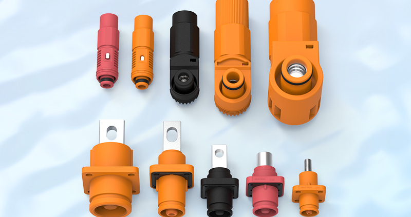
Tag Archive for: Energy Storage Connector

How Temperature Rise Affects High-Current Connectors

High-current connector selection often starts with one number: the rated current.

A customer may see “450A” on a product specification and reasonably assume that the connector can continuously carry 450A in any equipment environment.

That assumption can be dangerous.

Quick Answer:

Temperature rise in a high-current connector depends on current, contact resistance, conductor size, terminal design, material, ambient temperature, installation conditions, and heat dissipation. A 450A rating only applies under defined test conditions; actual continuous current may need to be reduced when ambient temperature or thermal loading increases.

That is why high-current connector engineering should focus not only on current rating, but also on thermal performance under real operating conditions.


Why High-Current Connectors Generate Heat

Every electrical connection has resistance.

Even when that resistance is very small, current passing through the interface generates heat.

The basic relationship is:

Power loss = I² × R

This is one of the most important relationships in high-current connector design.

If current doubles while resistance remains unchanged, the heat generated by resistive losses increases by a factor of four.

That means a resistance change that seems insignificant at 10A may become important at 300A or 450A.

For example, heat can develop at:

  • contact interfaces;
  • crimp connections;
  • busbar interfaces;
  • conductor transitions;
  • cable terminals;
  • bolted connections.

The goal is therefore not simply to achieve low resistance at the initial test.

The contact system must maintain low and stable resistance throughout its service life.


Contact Resistance Is One of the Main Heat Sources

Contact resistance is created where two conductive surfaces touch.

In a high-current connector, this usually occurs between the plug and receptacle terminals.

The resistance depends on several factors:

  • contact geometry;
  • effective contact area;
  • normal contact force;
  • surface roughness;
  • terminal material;
  • plating material;
  • contamination;
  • wear;
  • corrosion;
  • mating cycles.

A well-designed terminal provides sufficient contact pressure to maintain a stable conductive path.

If contact pressure becomes too low, resistance may rise.

This can lead to:

Higher resistance → More heat → Faster material degradation → Even higher resistance

That cycle can become a long-term reliability risk.

TE describes low contact resistance as one reason its high-power connector designs can reduce temperature rise and power loss. Molex similarly links low contact resistance with lower voltage drop and lower heat generation in its high-current COEUR-based interconnects.


Terminal Material Influences Thermal Performance

How Temperature Rise Affects High-Current Connectors

Terminal material must provide both electrical conductivity and mechanical stability.

Typical high-current connector contacts use copper or copper-alloy materials.

Pure copper offers excellent conductivity, but connector terminals also require mechanical properties such as:

  • strength;
  • spring stability;
  • formability;
  • fatigue resistance;
  • resistance to stress relaxation.

Depending on the terminal structure, manufacturers may therefore use different copper alloys to balance conductivity and mechanical performance.

Common options include:

  • high-conductivity copper;
  • brass;
  • phosphor bronze;
  • copper-nickel-silicon alloys;
  • other high-conductivity copper alloys.

FPIC’s internal connector materials identify alloys such as C7025, C7035, and C18400 as suitable options for higher-current applications because they provide a useful combination of conductivity and mechanical properties.

Material choice should therefore be based on both electrical and mechanical requirements.


Plating Also Affects Contact Stability

The base terminal material is only one part of the contact system.

The contact surface may use plating such as:

  • tin;
  • silver;
  • gold;
  • nickel underlayers.

For high-current power applications, silver plating is commonly used because of its conductivity and contact performance.

Tin can also be suitable in many applications, although friction, fretting, oxidation, temperature, and mating-cycle requirements must be considered.

The plating system affects:

  • contact resistance;
  • corrosion resistance;
  • wear;
  • friction;
  • temperature stability;
  • service life.

The correct plating is therefore determined by the application rather than by choosing the most expensive material.


Cable Cross-Section Directly Affects Temperature Rise

A connector cannot be evaluated independently from its cable.

The resistance of a conductor depends on:

Material resistivity × conductor length ÷ conductor cross-sectional area

In practical terms:

A smaller conductor generally has greater resistance and produces more heat under the same current.

This is why connector specifications normally define compatible cable sizes.

For example, a high-current interface might be designed around conductor sizes such as:

  • 35 mm²;
  • 50 mm²;
  • 70 mm²;
  • 95 mm²;
  • 120 mm²;
  • 150 mm².

The cable cross-section must match both:

  1. the required current capacity; and
  2. the terminal crimp or termination design.

Phoenix Contact provides a useful example: the same connector can have different permissible currents depending on whether it is used with 2.5 mm², 4 mm², or 6 mm² conductors. Its published derating example shows that conductor size and ambient temperature both materially change the usable current.


Crimp Quality Can Become a Hidden Heat Source

Even when the connector and cable are correctly sized, poor termination can create additional resistance.

For a crimped connection, engineers must control:

  • crimp height;
  • crimp width;
  • conductor position;
  • conductor compression;
  • strand damage;
  • bellmouth;
  • terminal deformation;
  • pull-out force.

A poor crimp can create:

  • insufficient conductor contact;
  • uneven current distribution;
  • localized resistance;
  • localized heating.

FPIC’s terminal crimping standards therefore treat crimp height as one of the most important production controls and also use pull-force and cross-section analysis to verify termination quality.

For high-current connectors, termination quality is part of thermal management.


Ambient Temperature Changes the Available Thermal Margin

Connector temperature is not determined by self-heating alone.

The final operating temperature is approximately influenced by:

Ambient temperature + temperature rise caused by current

This means the same connector may behave differently in:

  • a 25°C laboratory;
  • a 40°C industrial cabinet;
  • a 55°C BESS cabinet;
  • an outdoor enclosure exposed to solar heating.

If a connector housing or cable insulation has a maximum permitted operating temperature, higher ambient temperature leaves less room for self-heating.

Phoenix Contact describes current-carrying capacity as dependent on both self-heating and ambient temperature, and its derating curves show permissible current decreasing as ambient temperature rises.

This is why high-current connector selection should include a current-temperature derating curve, not only one headline ampere value.


Continuous Current Is More Important Than Short Peak Current

A connector may experience several types of current:

  • continuous operating current;
  • short peak current;
  • startup current;
  • overload current;
  • pulse current.

These loads do not create the same thermal effect.

A short-duration peak may not allow enough time for the complete connector assembly to reach thermal equilibrium.

Continuous current is different.

When current flows for a long period, the connector continues heating until the generated heat and dissipated heat reach equilibrium.

For BESS applications, this distinction is particularly important because energy storage systems can operate under sustained charging or discharging conditions.

Therefore, the engineering question should not only be:

What is the maximum current?

It should also be:

How long will that current flow?


Why “Rated 450A” Does Not Mean 450A Everywhere

This is the most important point of the article.

A current rating is normally determined under specified test conditions.

Those conditions can include:

  • ambient temperature;
  • conductor size;
  • conductor length;
  • contact configuration;
  • mounting arrangement;
  • temperature-rise limit;
  • airflow;
  • measurement location.

TE explicitly states that its published current ratings represent maximum continuous current under defined or optimum conditions and that derating factors must be applied for higher ambient temperature and multiple loaded circuits.

IEC 60512-5-1 defines a standardized method for evaluating connector temperature rise under current load, while IEC 60512-5-2 addresses current-temperature derating at elevated ambient temperatures.

Therefore:

450A means:

The connector has demonstrated a defined current-carrying capability under specified conditions.

It does not mean:

The connector can operate continuously at 450A in every enclosure, cable configuration, temperature, altitude, or cooling condition.

That distinction should always be explained clearly to customers.


Multiple Loaded Contacts Can Change Current Capacity

For multi-contact connectors, another factor appears: mutual heating.

When multiple adjacent contacts carry current simultaneously, each contact contributes heat to the connector housing.

This raises the internal temperature and can reduce the current that each contact can safely carry.

TE notes that the current capacity per contact decreases when multiple contacts are simultaneously used for power transmission.

This means engineers must define:

  • how many contacts carry current;
  • current per contact;
  • spacing between contacts;
  • conductor sizes;
  • enclosure temperature.

A single-contact rating cannot simply be multiplied by the number of contacts.


Connector Housing Material Sets Another Thermal Limit

The terminal is not the only component exposed to heat.

The housing, seals, cable insulation, and nearby materials also have temperature limits.

Typical connector housing materials include:

  • PA66;
  • PBT;
  • LCP;
  • PA6T;
  • PA9T;
  • PPS.

Different polymers provide different:

  • heat resistance;
  • mechanical strength;
  • moisture absorption;
  • dimensional stability;
  • flame performance.

FPIC’s internal engineering materials identify high-temperature materials such as LCP, PA9T, PA6T, PA46, and PPS for connector designs that must withstand elevated-temperature processes such as reflow soldering.

The thermal limit of the complete system should therefore reflect the lowest critical material limit, not only the copper contact.


High-Voltage BESS Cabinets Create More Difficult Thermal Conditions

Energy storage systems are a particularly relevant example.

Inside a BESS cabinet, multiple heat sources may exist:

  • battery modules;
  • busbars;
  • contactors;
  • fuses;
  • high-current connectors;
  • power conversion equipment;
  • cable bundles.

The cabinet itself may also have restricted airflow.

This means the connector operates within a larger thermal system.

Engineers must consider:

  • cabinet ambient temperature;
  • cable bundle temperature;
  • neighboring components;
  • ventilation;
  • cooling system design;
  • continuous charge/discharge profile.

For this reason, the connector temperature should ideally be evaluated inside a representative system environment rather than only through a catalog value.


Temperature Rise Testing Provides the Evidence

Temperature-rise testing helps determine how much the connector heats when current passes through it.

A typical test process includes:

  1. assemble the connector with the specified conductor;
  2. place temperature sensors at defined measurement points;
  3. record initial ambient and component temperature;
  4. apply the test current;
  5. wait until thermal equilibrium;
  6. record the maximum temperature;
  7. calculate the temperature rise;
  8. repeat at different current levels if required.

IEC 60512-5-1 specifically defines a test method for assessing current-carrying capability based on connector temperature rise.

The resulting data can then help generate a current-temperature derating curve.


What FPIC Tests During High-Current Validation

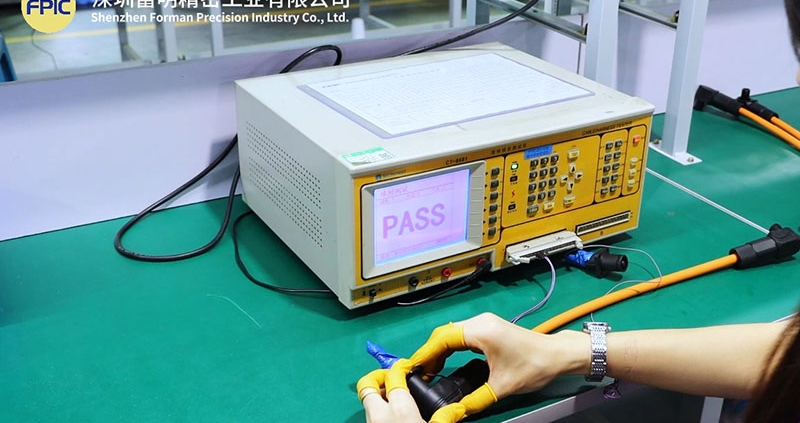
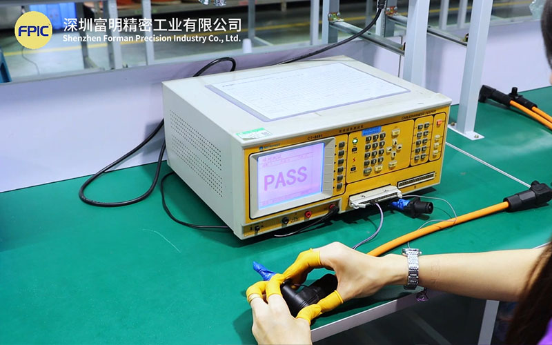
FPIC has dedicated equipment for connector electrical and thermal validation.

Our internal laboratory capability includes:

  • temperature-rise testers;
  • contact-impedance testers;
  • withstand-voltage testers;
  • insulation-resistance testing;
  • insertion and extraction force testing;
  • vibration testing;
  • thermal-shock chambers;
  • X-ray inspection;
  • dimensional inspection.

FPIC’s equipment list includes multiple temperature-rise testers and contact-impedance instruments, supporting validation of high-current connector and cable-assembly performance.

For high-current projects, the validation plan can evaluate:

  • connector temperature rise;
  • terminal resistance;
  • cable temperature;
  • crimp condition;
  • interface stability;
  • mechanical reliability.

Applying This to FPIC’s 2000V 450A Connector

FPIC’s high-current energy storage connector portfolio includes 2000V / 450A solutions for battery-system applications.

But the correct engineering message is not:

450A can always be used continuously.

The more technically credible message is:

The 450A platform is designed and validated for high-current energy storage applications under defined conditions, and final current capability should be confirmed against conductor size, ambient temperature, installation environment, and system thermal requirements.

This distinction strengthens rather than weakens the product story.

It tells engineers that FPIC understands how current ratings actually work.

For BESS customers, FPIC can support project evaluation based on:

  • system voltage;
  • continuous and peak current;
  • cable cross-section;
  • connector mounting;
  • ambient temperature;
  • cabinet cooling;
  • duty cycle;
  • required temperature-rise limit.

This moves the discussion from catalog selling to engineering selection support.


High-Current Connector and Cable Assembly Must Be Evaluated Together

For high-current systems, the connector and cable assembly form one electrical and thermal path.

The evaluation should include:

ComponentKey thermal factors
ContactMaterial, geometry, resistance, plating
TerminalCrimp structure and conductor interface
CableCross-section, material, length, insulation
Connector housingTemperature capability and heat dissipation
Busbar interfaceSurface area, contact pressure, resistance
CabinetAmbient temperature and airflow
LoadContinuous current, peak current, duty cycle

Ignoring any one of these factors can produce an incomplete thermal assessment.


A Practical High-Current Connector Selection Checklist

Before selecting a high-current connector, provide the following data:

Electrical Requirements

  • nominal voltage;
  • maximum voltage;
  • continuous current;
  • peak current;
  • peak duration;
  • duty cycle.

Cable Requirements

  • conductor material;
  • conductor cross-section;
  • cable outer diameter;
  • insulation temperature rating.

Thermal Environment

  • minimum and maximum ambient temperature;
  • enclosure temperature;
  • airflow;
  • cooling method;
  • nearby heat sources.

Mechanical Installation

  • panel mount or cable mount;
  • busbar connection;
  • cable orientation;
  • available space.

Validation Requirements

  • permitted temperature rise;
  • test current;
  • test duration;
  • applicable IEC, UL, or customer standards.

Providing this information allows engineers to evaluate the real usable current, not simply repeat the catalog rating.


Frequently Asked Questions

1. What causes temperature rise in a connector?

Temperature rise primarily comes from electrical resistance in contacts, terminals, crimps, conductors, and interfaces while current is flowing.

2. Does lower contact resistance reduce temperature rise?

Generally yes. Lower resistance reduces resistive power loss at a given current, assuming the rest of the thermal system remains unchanged.

3. Does a larger cable always reduce connector temperature?

A larger conductor usually reduces cable resistance and can improve heat conduction away from the interface, but connector geometry, terminal design, ambient temperature, and installation conditions must still be evaluated.

4. Can a 450A connector continuously carry 450A?

Only under the conditions for which the current rating has been established. Higher ambient temperature, different conductor sizes, restricted cooling, or other installation factors may require derating.

5. Why is temperature-rise testing important?

It verifies how the complete connector assembly behaves under current load and helps determine whether the contact, terminal, housing, and cable remain within permitted temperature limits.

6. What is a connector derating curve?

A derating curve shows how permissible current decreases as ambient temperature increases. It provides a more realistic selection tool than a single rated-current number.


Conclusion

Current rating alone does not define high-current connector performance.

Temperature rise depends on the complete electrical and thermal system:

current + resistance + conductor + material + ambient temperature + installation + duty cycle

For BESS and other high-power systems, this is why a 450A connector should be evaluated as part of the complete application rather than treated as an isolated 450A component.

FPIC supports high-current connector and cable-assembly projects with connector development, conductor and terminal matching, temperature-rise testing, contact-resistance measurement, prototype validation, and repeat-production quality control.

Discuss Your High-Current Connector Project

FPIC supports high-voltage and high-current interconnection development for BESS, battery systems, industrial equipment, and customized power applications.

Send us your voltage, current profile, cable specification, ambient temperature, installation method, and project drawings for engineering evaluation.

Email: info@fpiconn.com


Resources

  1. IEC. IEC 60512-5-1:2002 – Connectors for Electronic Equipment – Current-Carrying Capacity Tests – Temperature Rise.
  2. IEC. IEC 60512-5-2:2002 – Connectors for Electronic Equipment – Current-Temperature Derating.
  3. TE Connectivity. Battery Pack Connectors – Current Carrying Capacity, T-Rise and Derating.
  4. TE Connectivity. Power Connectivity – Current Rating and Derating Guidance.
  5. Phoenix Contact. Electrical Tests for Connectors – Current Carrying Capacity and Derating.
  6. Molex. SW1 High-Current Interconnects and COEUR Socket Technology.
Select High-Voltage Connectors for BESS Cabinets

BESS cabinets are getting more powerful, more compact, and more demanding. That is changing the way engineers and sourcing teams evaluate high-voltage connectors. What used to be treated as a simple power connection is now part of a broader discussion about safety, thermal stability, installation efficiency, and long-term operating risk.

If you are selecting connectors for a battery energy storage cabinet, the right question is no longer just “What voltage and current do I need?” A better question is “Which connector platform helps the cabinet operate more safely, integrate more cleanly, and remain easier to build and maintain over time?”

Why Connector Selection in BESS Cabinets Is Becoming More Strategic

A BESS cabinet is not just a box full of batteries. It is a system-level power architecture that must manage electrical load, temperature, mechanical layout, installation logic, maintenance access, and compliance expectations at the same time.

Inside that architecture, the connector sits in a critical position. It can link battery modules, racks, busbars, cabinet-level power paths, and distribution interfaces. That means connector selection affects much more than the simple ability to pass current.

A poorly chosen connector can create avoidable problems such as:

  • excess temperature rise at the interface
  • difficult routing in compact cabinet layouts
  • inconsistent installation on the production floor
  • polarity or mating mistakes during assembly or service
  • poor maintenance access during replacement
  • lower long-term reliability under real operating conditions

By contrast, a well-selected high-voltage connector helps make the cabinet safer, cleaner to integrate, and easier to manage over the full system lifecycle.

Start with the Real Application, Not Just the Catalog Spec

One of the most common mistakes in connector selection is to begin and end with rated voltage and rated current. Those values matter, but they do not tell the full story.

In BESS cabinet design, you should first define the real application environment:

1. Where is the connector used in the system?

A connector used for a battery rack interface does not always face the same requirements as one used for an internal cabinet power path or a service interface.

2. What load conditions will it actually see?

A catalog rating may look sufficient, but the real question is whether the connector can support the required current with stable contact behavior and acceptable temperature rise in the actual cabinet environment.

3. How will the connector be installed and serviced?

If the design requires fast, repeatable installation or easier field replacement, connector structure becomes just as important as electrical performance.

Selection becomes much easier when you treat the connector as a system interface rather than a standalone part.

Safety Should Be the First Screening Standard

In a high-voltage BESS cabinet, safety is not a secondary attribute. It is a first-level filter.

When reviewing connector options, teams should evaluate whether the design supports safer installation and operation in real conditions.

1. Touch-Proof Structure

Touch-proof design helps reduce the risk of accidental contact with energized conductive points. This is especially valuable during cabinet assembly, maintenance, and replacement operations.

2. Polarity Clarity and Anti-Misplug Design

In modular energy storage systems, polarity mistakes create unnecessary risk. Mechanical keying, coding, and clear positive/negative differentiation can help reduce installation errors.

3. Secure Mating Logic

A connector should provide stable electrical and mechanical engagement. Secure mating improves confidence during assembly and helps maintain contact stability during operation.

4. Application-Appropriate Compliance Direction

Many customers now consider compliance readiness earlier in the design cycle. Even when the final certification belongs to the complete system, connector selection still affects the path toward safer and more credible product integration.

Current Rating Must Be Evaluated Together with Thermal Performance

Current rating is still a basic selection parameter, but in BESS cabinets it should always be considered together with thermal performance.

Why? Because a connector that carries current on paper can still become a weak point in the cabinet if contact resistance is unstable or if heat builds up in a tight installation space.

That is why engineers should evaluate:

  • rated current
  • conductor compatibility
  • contact resistance stability
  • termination method
  • expected temperature rise
  • real cabinet airflow and space constraints

This is where high-current connector design becomes more than a numbers exercise. It becomes a thermal and reliability decision.

Installation Efficiency Matters More Than Many Teams Expect

In large-scale BESS deployment, installation speed and consistency matter. Connector design directly affects both.

A connector that supports a cleaner mating process, better cable routing, and clearer installation logic can help reduce:

  • assembly time
  • operator error
  • rework risk
  • field service time later

This is why the market is paying more attention to connector systems that improve installation, not only electrical transfer.

For BESS cabinet builders, connection efficiency can influence both production cost and long-term service experience.

Do Not Ignore Serviceability and Maintenance Access

BESS systems are long-life assets. That means maintainability should be part of connector selection from the beginning.

A connector that is difficult to reach, hard to disconnect, or easy to reconnect incorrectly may create future service cost even if it performs acceptably on day one.

Good high-voltage connector selection should therefore consider:

  • access during inspection
  • clarity during remating
  • replacement convenience
  • compatibility with modular cabinet design

In practice, the best connector is often the one that supports both stable operation and more predictable service work.

What to Look for in a High-Voltage Connector for BESS Cabinets

A practical selection checklist usually includes the following questions:

  • 1. Is the voltage platform aligned with the target system?

The connector should fit the actual platform requirement, whether the project is centered on 1000V, 1500V, or higher-voltage development.

  •  2. Is the current rating suitable for real cabinet conditions?

Do not treat rated current as an isolated number. Confirm the connector matches the true load path and thermal expectations.

  • 3. Does the structure support safer use?

Look for features such as touch-proof protection, mechanical keying, polarity control, and stable locking.

  • 4. Does it integrate well into the cabinet design?

Panel mounting logic, cable routing, space efficiency, and mating orientation all affect integration quality.

  • 5. Will the connector support installation and maintenance efficiency?

Selection should support not only the first assembly, but also future service and replacement.

Where FPIC’s 2000V 450A Energy Storage Connector Fits

For customers developing higher-voltage and higher-current BESS cabinet systems, FPIC’s 2000V 450A energy storage connector offers a strong option for projects that need more than a basic power interface.

This connector direction is relevant when the application requires:

  • higher-voltage connector capability
  • stronger high-current support
  • cabinet-level safety-oriented connection design
  • structured installation logic
  • improved routing flexibility
  • support for more advanced battery-system integration

FPIC’s energy storage connector development already includes features such as touch-proof design, 360° rotating plug structure, different installation keying options, and multiple connection methods, which are directly relevant to the practical needs of BESS cabinet integration.

That makes the product easier to position not just as a connector, but as part of a safer and more serviceable cabinet interconnection solution.

How FPIC Supports Broader Energy Storage Connector Needs

FPIC’s energy storage connector portfolio is not limited to one flagship product. Internal product materials already cover multiple platform levels, including 1000V and 1500V ES series configurations, with different current ranges and structural options for energy storage applications.

This broader platform logic matters because BESS customers do not all need the same interface level. Some projects focus on mainstream 1500V cabinet architectures. Others increasingly move toward higher-voltage, higher-current platforms where the 2000V 450A direction becomes more attractive.

That gives FPIC a stronger story in content marketing and customer communication:

  • 1000V and 1500V platforms support broader application coverage
  • 2000V 450A supports higher-power differentiation
  • safety-oriented structure supports BESS cabinet messaging
  • UL-related product positioning supports stronger credibility in global discussions

Select High-Voltage Connectors for BESS Cabinets

Final Recommendation

If you are selecting a high-voltage connector for a BESS cabinet, do not reduce the decision to voltage and current alone.

Instead, evaluate the connector from five angles:

  • safety
  • current and thermal stability
  • installation efficiency
  • cabinet integration fit
  • maintenance practicality

That approach leads to better system decisions and reduces the risk of solving one problem while creating another.

As the BESS market keeps moving toward safer, more integrated, and more serviceable systems, high-voltage connector selection will continue to play a larger role in overall cabinet design quality.

Contact FPIC

Looking for a high-voltage connector solution for BESS cabinets, battery racks, or high-current storage systems?

FPIC can support connector communication and product matching for energy storage applications, including higher-power projects that require stronger safety and integration logic.

Email: info@fpiconn.com
Website: fpiconn.com

Resources

  • Reuters. Lithium producers bet on battery storage as demand shifts beyond EVs. June 24, 2026.
  • Molex. Designing Battery Energy Storage Systems (BESS).
  • Phoenix Contact. Connectors for Energy Storage Systems.
  • Connector Supplier. Battery Connectors: The Unsung Heroes of BESS Applications.
450A energy storage connector UL certificate

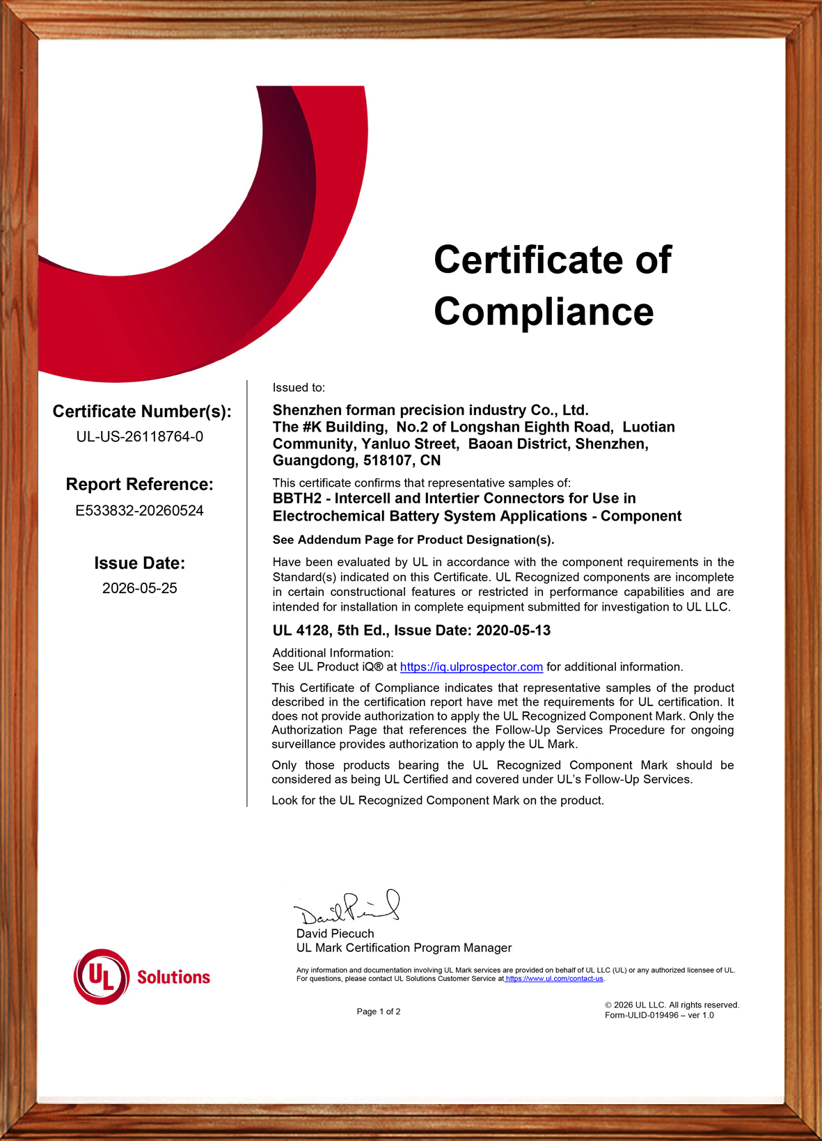
FPIC is pleased to announce that representative samples of our 2000V 450A energy storage connector series have been evaluated by UL for use in electrochemical battery system applications. The certification documents identify the product under UL 4128, 5th Edition, covering intercell and intertier connectors for battery system use.

This milestone strengthens FPIC’s capability in high-current battery interconnection solutions and provides additional confidence for customers developing energy storage equipment, battery packs, and related power distribution systems.

What This Certification Covers

According to the UL Certificate of Compliance, the evaluated product category is BBTH2 – Intercell and Intertier Connectors for Use in Electrochemical Battery System Applications – Component, with certificate number UL-US-26118764-0 and report reference E533832-20260524. The issue date is 2026-05-25.

The corresponding UL report describes the product as:

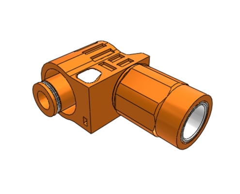
  • Cable Connectors
    Cat. Nos. A083-1F14-C150N-6A-##, A083-1F14-C150N-5A-##, A083-1F14-C150N-0A-##
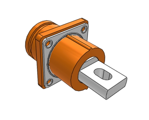
  • Panel Mounted Inlets
    Cat. Nos. A083-2M14-E014F-6A-##, A083-2M14-E014F-5A-##, A083-2M14-E014F-0A-##

The report also states the key ratings of this series as 2000V DC and 450A. For the cable connector version, the evaluated conductor size is 300 kcmil.

FPIC 450A Energy Connector Meets UL 4128

Why This Matters for Energy Storage Applications

High-current battery connection points in energy storage systems demand more than basic electrical performance. They also require controlled insulation design, reliable mating, proper polarity identification, and suitability for integration into complete battery equipment.

The UL report identifies these products as intercell/intertier connectors intended for use in electrochemical battery equipment, including cable connector and panel mounted inlet configurations. The panel mounted inlet versions are intended for factory assembly onto copper conductors rated 90°C or higher and/or copper or copper alloy busbars in battery equipment.

For ESS manufacturers, battery pack integrators, and related equipment developers, this provides an important compliance reference point when evaluating connector solutions for high-voltage, high-current battery system designs.

Key Product Characteristics

Based on the UL report, FPIC’s 450A connector series includes the following core characteristics:

1. High Voltage and High Current Capability

The evaluated series is rated at 2000V DC and 450A, supporting demanding battery interconnection applications.

2. Cable and Panel-Mounted Configurations

The series includes both cable connector and panel mounted inlet versions, helping customers build matching connection interfaces for different battery system architectures.

3. Single-Pole Intercell / Intertier Connector Design

The report describes the cable connector products as insulated, single-pole mating intercell/intertier connectors, suitable for battery system connection needs.

4. Support for Battery Equipment Integration

The panel mounted inlet versions are intended for assembly to busbars or conductors in electrochemical battery equipment, which is especially relevant for energy storage cabinets, battery packs, and related systems.

Important Compliance Note

The UL certificate clearly states that these are UL Recognized components, not complete end-use equipment. It also states that the certificate itself does not provide authorization to apply the UL Recognized Component Mark; only products bearing the appropriate UL Recognized Component Mark and covered under UL follow-up services should be considered UL Certified within that program context.

In addition, the UL report notes that these devices are:

  • not suitable for disconnecting under load
  • not intended for use outside an equipment enclosure
  • not investigated for an environment rating
  • intended for use only in complete equipment where acceptability is determined in the end-use application

This is important for customers who are designing certified end products and need to evaluate the connector as part of the complete system.

What This Means for FPIC Customers

This UL milestone demonstrates FPIC’s continued progress in energy storage connector development and supports our ability to serve customers with more robust interconnection solutions for battery system applications.

For customers working on:

  • energy storage systems
  • electrochemical battery equipment
  • battery pack integration
  • power distribution interfaces
  • high-current cabinet connections

this development provides stronger confidence in FPIC’s capability to support demanding connector projects with both product development and manufacturing execution.

FPIC Energy Storage Connector Capability

FPIC has been continuously developing energy storage connector solutions for high-current and high-voltage applications. Our energy storage product direction includes connector and cable solutions designed for battery modules, battery packs, and related ESS equipment. FPIC’s internal product materials also describe energy storage connectors with features such as touch-proof design, multiple connection methods, and compliance direction aligned with UL 4128.

This new 450A certification-related progress further strengthens FPIC’s position in the energy storage connector segment.

Contact FPIC for Energy Storage Connector Projects

If you are developing battery packs, ESS cabinets, or related electrochemical battery equipment and need a reliable high-current connector solution, FPIC can support your project with product information, engineering communication, and manufacturing support.

Contact us to discuss your application requirements.

Energy storage connector solutions

As the world transitions to a low-carbon future, energy storage systems (ESS) are becoming the cornerstone of modern power infrastructure. Whether supporting renewable energy, electric vehicles (EVs), or smart grids, the efficiency and reliability of these battery systems rely heavily on one often-overlooked component: the connector.

At Forman Precision Industry Co., Ltd (FPIC), we understand that high-performance energy storage connectors are not just accessories — they are essential to unlocking the full potential of battery technology. In this article, we explore the critical role that connectors play in advanced battery systems, the technologies behind them, and how we help customers deliver safer, smarter, and more efficient energy solutions.


Why Connectors Matter in Energy Storage Systems

Modern battery energy storage systems (BESS) must manage high voltage, high current, and intense thermal conditions — all while maintaining system integrity, safety, and longevity. The right energy storage connector:

  • Enables low-resistance power transmission

  • Ensures safe, secure connections under high voltage (often up to 1500V)

  • Simplifies maintenance and scalability

  • Supports modular battery pack design

  • Improves system uptime and reliability

Without high-quality, purpose-built connectors, energy storage systems risk voltage drops, heat generation, and even failure under dynamic operating conditions.


Key Types of Connectors in Battery Systems

? High-Voltage Battery Connectors

These are used in EV battery packs, grid-scale storage, and renewable energy systems. They’re engineered to support up to 1500V and currents from 100A to 350A or more, making contact resistance, insulation, and heat dissipation critical design considerations.

? Modular Energy Storage Connectors

Often used in lithium-ion battery modules and racks, these connectors allow for quick-disconnect, easy maintenance, and plug-and-play configurations — ideal for scalable ESS solutions.

? Power Connectors for Battery Management Systems (BMS)

These connectors provide signal and control data, ensuring real-time monitoring of battery temperature, voltage, and performance. They must offer stable contact, low noise, and shielding from electromagnetic interference.


Connector Design Factors that Influence Energy Storage Efficiency

Current-Carrying Capacity

High-power energy storage connectors must be engineered for low contact resistance to avoid power loss and reduce heating, improving overall system efficiency and energy density.

Thermal Management

Thermal buildup can damage batteries and reduce lifespan. Connectors designed with optimized conductor paths and heat-resistant materials improve safety and energy efficiency.

Vibration & Shock Resistance

In mobile and industrial ESS applications, connectors must withstand mechanical stress, maintaining a secure connection without performance degradation.

Ingress Protection (IP Ratings)

Connectors used in outdoor or industrial environments must meet IP67/IP68 standards, ensuring protection from dust, water, and contaminants.

Material Quality

Premium copper alloys, gold-plated or silver-plated contacts, and high-performance thermoplastics are vital for corrosion resistance, conductivity, and long service life.


FPIC’s Energy Storage Connector Solutions

At FPIC, we deliver complete connector and cable assembly solutions designed specifically for battery storage and high-voltage applications.

? Custom Prototyping – Our engineering team works closely with clients to design and develop tailored connector solutions that match voltage, current, and installation needs.
? Cable Assembly Integration – We offer factory-assembled harnesses to reduce installation errors and support modular ESS deployment.
? In-House Testing – All products undergo stringent testing, including hipot testing, insulation resistance, salt spray, and temperature cycling, ensuring compliance with UL, TUV, and CE standards.
? Fast Sampling & Scalable Production – From pilot runs to mass manufacturing, FPIC supports your product launch and scale-up timelines.


Applications of Energy Storage Connectors

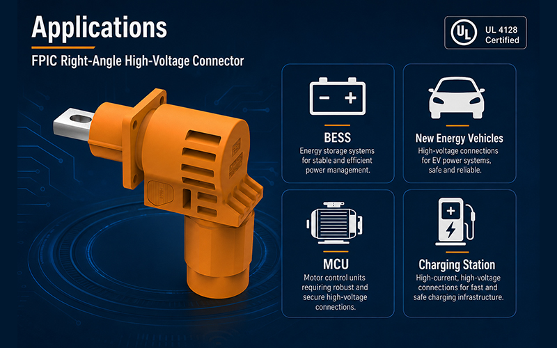
Our high-voltage energy storage connectors are widely used in:

  • Grid-tied energy storage systems

  • Solar and wind energy battery backup systems

  • Electric vehicle (EV) battery packs and charging stations

  • Uninterruptible power supplies (UPS)

  • Telecom power and industrial automation


End-to-End Value with FPIC

Choosing FPIC as your energy storage connector supplier means gaining a technology partner with deep experience in:

  • Connector R&D and precision manufacturing

  • Wire harness assembly and customization

  • System-level design support for modular battery applications

  • ISO 9001, ISO 14001, IATF 16949, and VDA 19.1 certified processes

We don’t just supply components — we build long-term connectivity solutions that drive performance, safety, and scalability.

Energy storage connector solutions


Conclusion

As energy storage continues to evolve and expand, the demand for smarter, safer, and more efficient connectors will only grow. The right high-voltage connector improves thermal performance, simplifies integration, and enhances the overall reliability of battery systems.

At Forman (FPIC), we are committed to driving energy innovation forward — one powerful connection at a time.

? Ready to advance your energy storage design? Contact us today at info@fpiconn.com or visit www.fpiconn.com to explore our solutions.

high voltage connectors test

As industries rapidly evolve towards electrification, renewable energy, and energy storage systems (ESS), the demand for high-voltage connectors with superior performance and uncompromised safety is higher than ever. At Forman Precision Industry Co., Ltd (Forman), we lead the way in high-voltage connector innovation, offering customers end-to-end solutions — from custom prototyping and sampling to full mass production, backed by our own in-house testing laboratory and assembly lines.

In this article, we explore the latest engineering innovations behind high-voltage connector design, and how Forman helps customers achieve better performance, greater safety, and faster time-to-market.

high voltage connectors test


The Need for Innovation in High-Voltage Connectors

Modern energy systems — whether in electric vehicles (EVs), battery storage systems, industrial automation, or solar power plants — require connectors that:

  • Handle higher voltages and currents safely

  • Operate reliably in harsh environments

  • Offer easy installation and maintenance

  • Meet international safety and quality standards

To meet these growing demands, connector design must continually advance with new materials, smarter structures, and tighter manufacturing tolerances.


Key Innovations Driving High-Voltage Connector Design

? 1. Advanced Insulation and Sealing Technologies

Today’s connectors must withstand up to 1500V or higher, demanding superior dielectric materials and multi-layer insulation structures.

  • Enhanced creepage and clearance distances to prevent arcing

  • IP67/IP68 sealing to protect against dust, water, and contaminants

  • Thermal-resistant materials to ensure stability in high-temperature environments

At Forman, we use advanced polymer compounds and precision molding techniques to achieve the highest insulation reliability.


? 2. Compact, High-Current Designs

Space-saving without sacrificing performance is key.

  • Optimized contact geometries to support higher current loads with lower resistance

  • Smaller form factors to fit into tight system architectures

  • Shielded designs to minimize electromagnetic interference (EMI)

Forman’s high-voltage connectors are engineered for maximum current density while maintaining excellent thermal management.


? 3. User-Centric Mechanical Designs

Ease of use is critical for efficient installation and service.

  • Push-pull locking mechanisms for one-handed, secure connections

  • Color-coded interfaces and keying options to prevent misconnection

  • Quick-disconnect safety features for emergency shutdowns

Our connectors are not only reliable but engineered for intuitive and safe operation — even under high-load conditions.


Forman’s Full-Service Capabilities for High-Voltage Connectors

At Forman, we offer a true end-to-end service, bringing your project from concept to reality under one roof:

Custom Prototyping and Design Engineering

  • We support customers from early concept to functional prototypes with flexible design iterations.

  • Tailor connector size, shape, performance specs, and cable assemblies to fit your project perfectly.

Sampling and Pilot Production

  • Small-batch production available for validation testing and early-stage integration.

  • Full engineering support throughout sample refinement and optimization stages.

Mass Production

  • Scalable production with strict process control, traceability, and ISO/IATF quality certifications.

  • In-house automated assembly lines for energy storage connector assemblies with cables ensure fast, consistent output.

Comprehensive In-House Testing Laboratory

  • Electrical performance validation: Continuity, insulation resistance, hipot testing

  • Mechanical robustness tests: Vibration, tensile strength, pull force tests

  • Environmental testing: Thermal cycling, salt spray, humidity resistance

  • Advanced color analysis and dimensional inspection for 100% quality assurance

Every Forman connector is rigorously tested to meet or exceed international standards before reaching our customers.


Applications We Support

? Energy Storage Systems (ESS)
? Electric Vehicles (EV) and Charging Stations
? Industrial Automation & Robotics
? Renewable Energy Plants (Solar, Wind)
? High-Performance Battery Packs


Why Partner with Forman for Your High-Voltage Connectivity Needs?

20+ Years of Expertise in precision metal and plastic parts manufacturing
Certified Quality – IATF 16949, ISO 9001, ISO 14001, VDA 19.1, RoHS, REACH compliant
Fast Turnaround from prototyping to mass production
Customized, Scalable Solutions tailored to your project
One-Stop Service – From design to testing to final product delivery


Conclusion

As industries continue to electrify and demand higher performance, innovative high-voltage connector design will be the cornerstone of safer, more reliable systems.
At Forman, we are ready to engineer the future with you — delivering tested, proven, and customized connectivity solutions that empower your success.

? Ready to start your project? Contact us today at info@fpiconn.com — let’s innovate together! ?

energy storage connector application

As the demand for energy storage systems (ESS) grows rapidly across renewable energy, electric vehicles, and industrial sectors, the importance of reliable, high-performance connectors cannot be overstated. Energy storage connectors are critical to ensuring safe, efficient, and durable operation of these complex systems.

In this article, we’ll walk you through the best practices for selecting and installing energy storage connectors to help maximize system performance and longevity.

energy storage connector application


1. Understand Your Application Requirements

Before selecting a connector, you must clearly define the operational conditions and performance needs of your energy storage system.

? Voltage and Current Ratings
Choose connectors that can handle the system’s maximum voltage and current levels without overheating or degradation. For instance, in large battery packs, you may need 1500V high-voltage connectors capable of managing hundreds of amperes safely.

? Operating Environment
Consider environmental factors like:

  • Temperature range

  • Vibration and mechanical stress

  • Exposure to moisture, dust, or chemicals

Look for connectors with IP67/IP68 ratings and corrosion-resistant materials for outdoor or industrial settings.

? Standards and Certifications
Ensure connectors comply with relevant standards such as UL, TUV, CE, and RoHS for quality, safety, and environmental protection.


2. Choose the Right Connector Type

Depending on your system design, different types of energy storage connectors may be needed:

? High Voltage Energy Storage Connectors
Designed for large ESS systems, capable of handling high power safely and efficiently.

? Battery Storage Connectors
Specially built for modular battery pack connections, ensuring low resistance and secure locking mechanisms.

? Power Connectors for Batteries
Robust designs that handle high currents with minimal heat generation and maximum efficiency.

Tip: Always consider using shielded connectors in environments where electromagnetic interference (EMI) may be a concern.


3. Pay Attention to Connector Materials

Material selection impacts the performance, safety, and durability of connectors:

Contact Materials: Look for connectors with silver or gold-plated contacts to enhance conductivity and prevent corrosion.
Housing Materials: Choose housings made of high-grade plastics or thermoset composites for mechanical strength and thermal resistance.
Sealing Materials: Ensure sealing materials are compatible with operating temperatures and chemical exposure.


4. Best Practices for Installing Energy Storage Connectors

Proper installation is just as crucial as selecting the right connector:

? Follow Manufacturer Guidelines
Always refer to the manufacturer’s installation instructions to prevent damaging the connectors or compromising system performance.

? Secure Connections
Use proper torque specifications when tightening connectors to ensure solid, vibration-resistant electrical contact. Avoid over-tightening, which could crack housings or damage contacts.

? Inspect and Clean Mating Surfaces
Before mating, clean connectors thoroughly to remove dust, oils, or debris that could affect conductivity or sealing.

? Use Appropriate Tools
Employ recommended crimping, assembly, and installation tools to achieve proper fits and to avoid physical stress on cables and terminals.

? Double-Check Polarity and Wiring
Incorrect wiring can cause system failures or safety hazards. Always double-check wiring diagrams and polarity before final installation.


5. Plan for Maintenance and Serviceability

When designing your energy storage system, choose connectors that allow easy access for maintenance, replacement, and upgrades. Quick-connect/disconnect features can significantly reduce downtime during servicing.

Regular inspections should include:

  • Checking for signs of wear, corrosion, or overheating

  • Verifying locking mechanisms remain secure

  • Testing for electrical continuity and insulation integrity


Conclusion

Selecting and installing the right energy storage connectors is critical to ensuring the safety, efficiency, and longevity of modern energy systems. By following these best practices, manufacturers, integrators, and system designers can deliver more reliable and cost-effective energy storage solutions.

At Forman (FPIC), we specialize in high-voltage connectors, battery storage connectors, and customized energy storage solutions designed to meet the most demanding industrial and renewable energy applications.

? Need expert advice or custom connector solutions? Contact us today at info@fpiconn.com! ?

Tag Archive for: Energy Storage Connector