metal mold assembly

Introduction

Metal stamping molds are essential in manufacturing industries, enabling precise and efficient production of metal components. The mold assembly process plays a critical role in ensuring the quality, durability, and accuracy of stamped parts.

In this article, we will walk you through the complete metal stamping mold assembly process, covering essential steps, best practices, and quality control measures. Whether you are a mold engineer, manufacturer, or industry professional, this guide will provide valuable insights into achieving high-performance stamping molds.

I. Pre-Assembly Preparation

Before starting the assembly process, it is crucial to prepare the necessary tools, measuring instruments, and reference documents to ensure smooth execution.

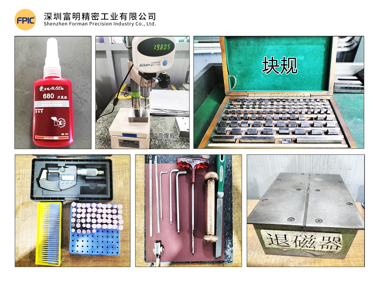
1. Tools & Measuring Instruments

Ensure that the required tools and measuring instruments are available, including:

  • Hand tools: Wrenches, files, copper hammers
  • Surface finishing tools: Oil stones, sandpaper, pneumatic grinders, polishing heads
  • Cleaning agents: Mold cleaner
  • Adhesives & lubricants: 680 glue
  • Measuring instruments: Vernier calipers, micrometers, gauge blocks, thin shims, demagnetizer, etc.mold tools

2. Understanding the Mold

Before assembly, review all relevant drawings:

  • Product drawings
  • Layout drawings
  • Mold part drawings

3. Mold Assembly Process Overview

Familiarize yourself with the entire mold assembly process:

  1. Main Plate Gluing (Clamping Plate + Stripper Plate + Bottom Plate)
  2. Template Assembly
  3. Clamping Plate Component Assembly
  4. Stripper Plate Assembly
  5. Bottom Plate Assembly
  6. Upper & Lower Mold Matching & Confirmation
  7. Mold Base Gluing (Upper & Lower Mold Base)
  8. Installation of Standard Components
  9. Trial Stamping & Sample Testing


II. Template & Component Inspection Before Assembly

1. Template Inspection

Material & Hardness Verification: Ensure templates have undergone deep-freezing and stabilization treatment.
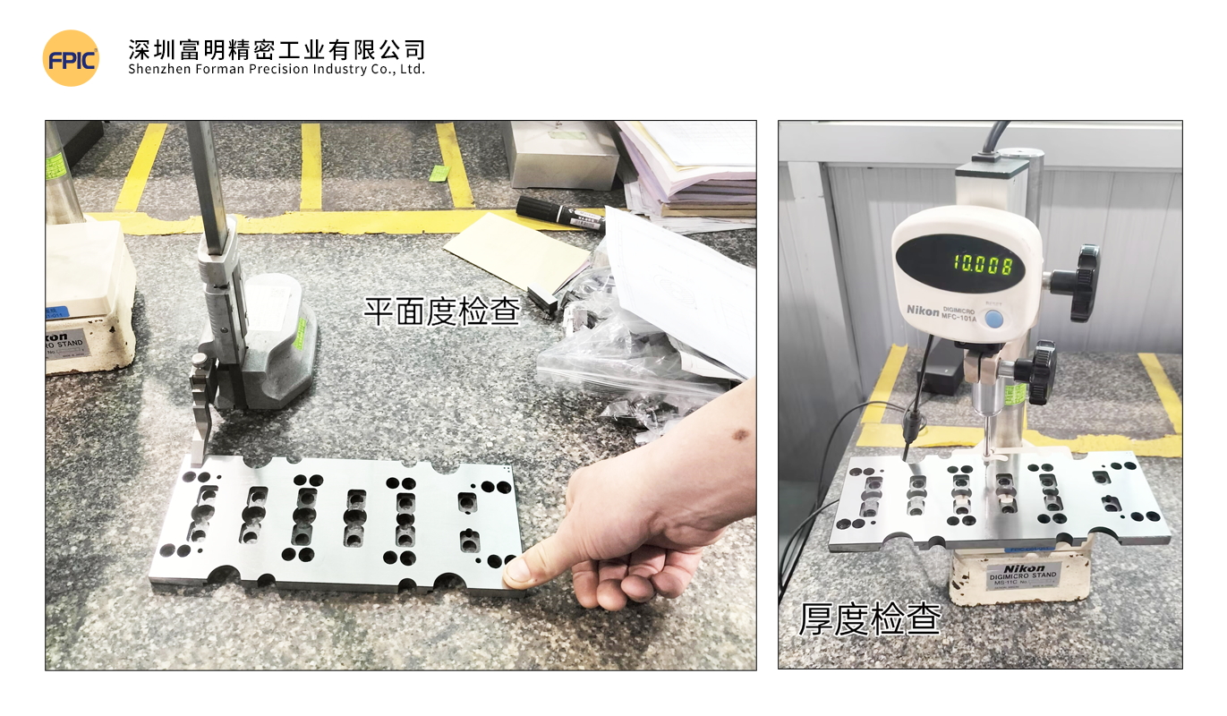
Flatness & Warping Check: Warping should not exceed 0.005mm per 100mm.
Hole Position & Processing Accuracy: Verify drilled holes, allowances, and surface finish.
Screw Hole Depth & Alignment: Check threaded hole depth and perpendicularity for proper fastener fitment.
Embossing & Pressing Grooves: Ensure correct width and depth.
Labeling & Marking: Verify mold number, material width, pitch, and part name.

2. Component Inspection

  • Material, Quantity & Hardness Verification
  • Dimensional Accuracy Check

Proper inspection eliminates potential errors that could cause misalignment, improper fits, and structural weaknesses in the final mold.

III. Template Machining & Finishing

1. Mold Base Preparation

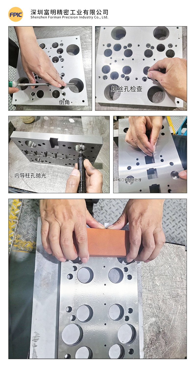
  • Clean all threaded holes of debris; check for damaged or unthreaded holes.
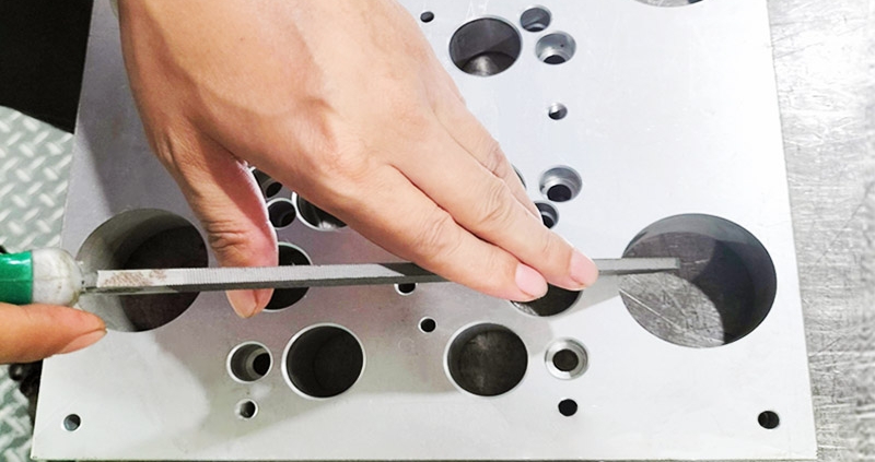
  • Deburr sharp edges and corners using a flat file.
  • Polish the surface with an oil stone to remove burrs.

2. Hole Deburring & Edge Rounding

  • Use round oil stones, files, grinders, and sandpaper for chamfering insert holes, round holes, and square holes.
  • Remove oxidation residues from wire-cut holes using fiber oil stones and round rods.

3. Surface Finishing

  • Polish the template with fine oil stones in the direction of the grinding pattern.
  • Use lubricating oil during polishing to prevent scratches.
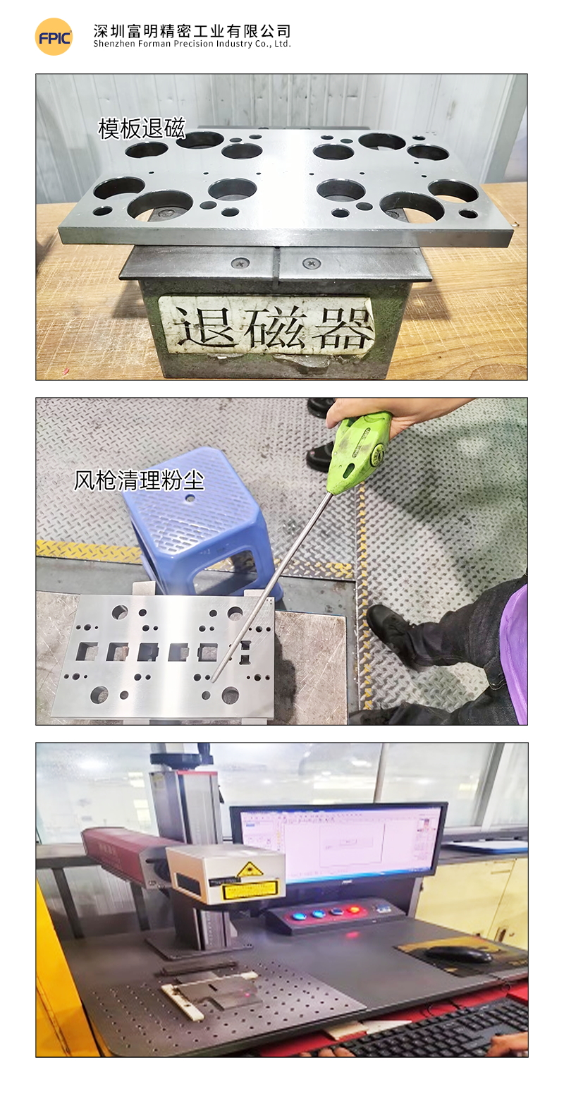
Mold Base & Template Finishing

4. Demagnetization

  • Use a demagnetizer to remove magnetism from the mold base and all components to prevent iron powder absorption, which could affect assembly accuracy.

5. Cleaning

  • Clean templates thoroughly using mold cleaner and compressed air.
  • Precision mold assembly requires a high level of cleanliness to ensure optimal performance.

6. Component Handling

  • Engrave part numbers on components.
  • Add lead-in angles to guide posts.
  • Sort, match, and demagnetize all parts.mold cleaning

Tip: Precision molds require extreme cleanliness to prevent defects in stamped parts.

IV. Measurement & Alignment Verification

1. Template Parallelism Measurement

  • Fix a dial indicator to zero on a reference platform and measure.
  • Standard tolerance: ≤ 0.002mm.

2. Template Warping & Deformation Check

  • Press one end of the template and observe dial indicator changes at the other end.
  • Deformation should not exceed 0.003mm.

3. Main Template Parallelism & Warping Measurement

  • Tolerance should not exceed 0.005mm.

4. Guide Post & Guide Bushing Measurement

  • Ensure guide posts conform to the required dimensions and roundness.
  • Measure guide post fitment and machining accuracy per the drawings.Measurement & Quality Control

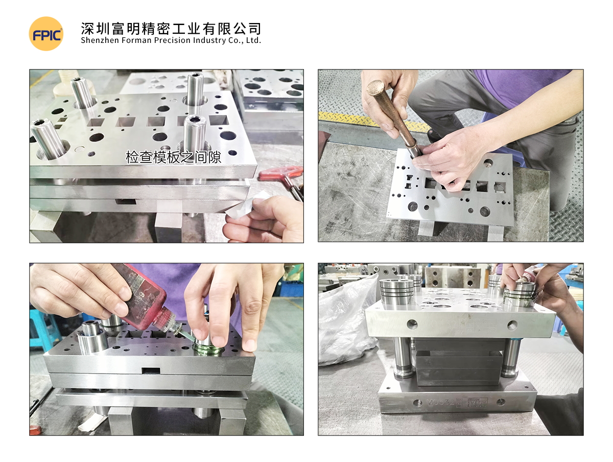
V. Mold Gluing Process

1. Gluing Steps

Step 1:

  • Use 0.005mm shims to check for gaps after mold closure.
  • The mold is qualified when shims cannot enter the gap.

Step 2:

  • After confirming the main template, insert a 10mm positioning pin from the clamping plate to the bottom plate to align the three primary templates.
  • If any gaps exist, check for debris or interference before proceeding.

Step 3:

  • Clean guide post and guide bushing thoroughly.
  • Insert guide posts into the stripper plate and secure with screws.
  • Place 0.2mm steel shims in each guide bushing hole.

Step 4:

  • Apply 680 glue evenly on the guide bushings while rotating them for even distribution.
  • Slowly insert guide bushings into the template until they rest against the steel shims.
  • Repeat for all guide bushings.Mold Gluing ProcessVI. Standard Component Assembly

1. Standard Component Inspection

  • Verify that all standard parts meet specifications.

2. Height & Position Check

  • Confirm the heights of floating pins, equal-height sleeves, limit posts, guide pins, and ejector rods.

3. Standard Component Installation

  • Clean all round holes before inserting components.
  • Install components into the mold cavity in order.

4. Final Confirmation

  • Ensure all parts are flat and properly fitted.
  • Verify free movement of standard components.
  • Check for clogged scrap ejection holes.
  • Ensure adjustment rods are correctly positioned and do not interfere with other templates.

VII. Mold Testing & Issue Documentation

1. Mold Closure Height Verification

  • Record closure height in the Mold Testing & Issue Report.

2. Manual Mold Closure Test

  • Close the mold manually to check for proper spring compression.

3. Trial Stamping & Sample Testing

  • Record initial data for comparison in subsequent trials.
  • Repeat trials until samples meet specifications.

4. Issue Analysis & Data Collection

  • Document all design & machining issues.
  • Analyze the root cause and record corrective actions.
  • Collect data for future design optimizations.

Example: Mold Testing & Issue Report

Date Issue Description Corrective Action Design Issue Machining Issue Resolution Date Result Responsible Person
2.18 Tight-fitting D07 forming part Wire-cut rework 2.18 Normal Engineer A
2.19 S05 part causing ejection failure Added ejector structure 2.19 Normal Engineer B
2.19 Dimension 2.02mm undersized Added 0.02mm shim 2.19 Normal Engineer B
2.20 Sent for FAI inspection 2.20 QA Inspector

 Note: All mold trials must be fully documented, ensuring a complete history of deviations and corrective actions.

Conclusion

The metal stamping mold assembly process requires precision, attention to detail, and strict quality control to ensure high-performance and long-lasting molds. By following these structured steps—from pre-assembly preparation to final testing—manufacturers can optimize efficiency, reduce downtime, and improve mold longevity.

Implementing these best practices will help ensure high-quality stamped parts, reducing waste, rework, and production costs.

Looking for High-Quality Metal Stamping Solutions?

At FPIC, we specialize in precision mold manufacturing with a focus on quality, efficiency, and innovation. Contact us today to learn more about our custom mold solutions!

Get in touch with us today!

metal stamping mold

Metal stamping is a crucial manufacturing process, shaping raw materials into precision components used across various industries. At the heart of this process are the metal stamping molds, instrumental in achieving consistency, accuracy, and efficiency in production. The standardization of these molds plays a pivotal role in elevating the quality of stamped parts and streamlining the entire manufacturing workflow.

1. Mold Design Standard Structural Diagram
metal stamping molds

No. Standard Parts Diagram
A Upper Limit High Pillar: Functions to ensure the precision of mold closure and prevent parts from being damaged.
B Upper Mold Spring and Equi-height Sleeve: Functions to aid in ejecting the molded part
C Upper Mold Pin: Functions to precisely fix and locate the upper mold base, upper bolster, and clamp plate.
D Upper Mold Screw: Functions to secure the mold plate.
E Misumi Inner Guide Post and Guide Sleeve: Functions to bear the precision of the entire set of mold components.
F Misumi Outer Guide Post and Guide Sleeve: Functions to bear the precision of mold components and ensure alignment between upper and lower molds.
G Ejector Pin: Functions to fix and position the fixed plate and ejector plate.
H Ejector Screw: Functions to secure the mold plate.
I Lower Limit High Pillar: Functions to ensure the precision of mold closure and prevent parts from being damaged.
J Lower Mold Screw: Functions to secure the lower mold plate.
K Lower Mold Pin: Functions to precisely fix and locate the lower mold base, lower bolster, and lower mold seat.

2. Standard Specifications for the Layout of Material Strips in Mold DesignLayout of Material Strips in Mold Design

No. Layout Diagram
1 Holes with high positional tolerance requirements or those prone to breakage need to be punched simultaneously; as shown in figures 1/2.
2 If there are holes for bending or other processes with high positional accuracy requirements, punch them after bending.

This can avoid inaccuracies in unfolding that may affect dimensions; as shown in figures 11/12 for bending, and figure 13 for cutting after bending.

3 In cases where there is symmetrical bending in the product, synchronous bending needs to be designed; as shown in figures 21/22/23.
4 Processes like stretching or others that may affect dimensions during forming need to be addressed in advance;

as shown in figure 10 with stretching first, followed by forming in figures 15/16.

5 For variations in the production process, adjustments to parts need to be increased, reducing the need for maintenance of the

lower mold during production; as shown in figure 19.

3. Design Standards for Mold Components

Cutting Station Design Standards

  • The drawing should specify the processing technology, where K represents fast cutting, M represents slow cutting, Y represents grinding, F represents discharge machining, X represents milling, PG represents wire cutting, and YG represents oil cutting. For precision blade drawings, the requirements are YG oil cutting – Y grinding – F discharge machining.
  • Material selection for components, such as ASP23, ASP60, WC, DC53, SKD11, SKH-9, SKH-53. Different materials should be applied based on the characteristics of the plate. For cutting punches, ASP60 with an HRC of 62 degrees is prioritized.
  • For soft materials with a thickness t < 1MM, the blade gap is c = (3%-4%) t; for t = 1MM-3MM, the blade gap is c = (5%-8%) t; for t = 3MM-5MM, the blade gap is c = (8%-10%) t.
  • For hard materials with a thickness t < 1MM, the blade gap is c = (4%-5%) t; for t = 1MM-3MM, the blade gap is c = (6%-8%) t; for t = 3MM-8MM, the blade gap is c = (8%-13%) t.
  • Try to avoid designing rectangular punches, as rectangular punches are prone to waste jumping.
  • For blade widths less than 1.0mm (round holes less than 1.0mm in diameter), for easy processing and improved accuracy, the blades need to be processed separately.
  • Punches should avoid excessively long and narrow grooves, and sharp corners should be avoided as much as possible. The length of small punches should be kept as short as possible, with appropriate reinforcement added.
  • Punches should be designed with an anti-stripping structure, considering the reduction of discharge machining.

    Design Standards for Forming Components
    Standard for the fit clearance of forming punches, standard for the springback parameters of parts with R-angle bending, referring to the “Springback Value Table.” Depending on the hardness of the material, the greater the hardness, the larger the values can be.

    Springback Standard for R≤5 Bending

    Material Thickness Bending Angle
    >90° <90° 90° Empty
    Stainless steel Phosphor/ Bronze/ Beryllium copper T<0.3mm 3°-5° 2°-4° 0.1-0.2° 5°-10°
    T>0.3mm 2°-4° 2°-3° 0.1-0.2° 4°-8°
    Iron material/ Bronze/Red copper T<0.3mm 1°-3° 2°-3° 0.1-0.2° 2°-4°
    T>0.3mm 1°-2° 1°-2° 0.1-0.2° 1°-3°

4. Template Block Design and Processing Standards

  • Precision requirements for template processing: machining tolerances and special manufacturing processes.
  • For template templates longer than 500mm, split design is required; all molds need to have process reference holes.
  • The processing accuracy of mold template parts in the whole set is required to be controlled within ±0.01mm, and the surface roughness of the template is required to be less than 0.4um.
  • For the blanking holes, stacking bodies, and oil cutting of the blanking plate and lower template, all fixed pin holes are treated with JG grinding; the sliding fit clearance C+ (0.005-0.010mm), non-sliding fit clearance C+0.003mm, machining accuracy ±0.002mm.
  • For the upper template, blanking plate, and lower template, the use of Misumi internal guide pins and guide bushes filled with glue improves guiding accuracy to ensure the positional accuracy of the template during production.
  • After heat treatment, the template undergoes super-deep cryogenic aging treatment, and some may require stabilization treatment to eliminate internal stress, prevent grinding deformation, and ensure template flatness of 0.005mm.

5. Mold Inspection Requirements

  • Verify that punches, inserts, dimensions of template length, and thickness conform to the drawing specifications.
  • Check the condition of screw holes and threading; assess the fit clearance of internal and external guide pillars; inspect for any missed wire cutting.
  • Measure the thickness dimensions of the template, and a difference of within 0.005mm in four-point measurements is considered acceptable.
  • Inspect the relinquishment processing status; ensure that the hole diameters and counterbore depths of various template through-holes comply with the drawing specifications.
  • Examine whether each hole is eccentric, assess the alignment of templates, and check the normality of positioning pins.
  • Apply chamfering to the periphery of the template. Include mold identification details on the sides, such as mold number, part number, material code, pitch, material width, mold closing height, and other parameters.

6. Mold Assembly Standards

  • Mold assembly is divided into two parts, upper and lower, assembled separately, and finally, the upper and lower molds are assembled together.
  • Firstly, understand the mold drawings, product information, analyze the mold structure, and comprehend the design intent of the mold.
  • Chamfer, polish, engrave, and categorize the templates and parts.
  • Use specialized positioning tools for installing internal and external guide pins and bushings to ensure their verticality during the positioning and gluing process.
  • Ensure smooth assembly of punches and block pairs, and appropriate force when tapping parts.

7. Mold Spare Parts Detailed Management

For molds accommodating multiple machine types, each part is assigned a unique number for clear and separate storage. This facilitates efficient replacement during the production process, expedites effective mold assembly, and reduces downtime during the production line changeover.

Spare Part Temporary Storage Area       Spare Parts Temporary Storage Area

Figure 1: Spare Part Temporary Storage Area

Parts are systematically arranged for easy visibility and subdivided into spare parts, blade components, machine-specific parts, molding parts, and standard components.

8. Continuously Optimize Part Structures, Validated Parts as Design Standards

Emphasizing technological innovation in designing parts: Figure 1 depicts a symmetric part that, once subjected to bending wear during the production process, becomes unusable. In Figure 2, a design optimization involves disassembling the part and redesigning the bending position as a double-sided molded part. Wear can be mitigated by turning to the other side for forming, effectively reducing processing costs and production downtime.

Optimize Part Structures

Conclusion:

In the dynamic landscape of metal stamping, the standardization of molds emerges as a cornerstone for operational excellence. It not only ensures the reliable production of high-quality parts but also positions manufacturers to adapt swiftly to industry advancements. As technology continues to reshape the manufacturing landscape, the role of standardized metal stamping molds becomes increasingly critical in driving efficiency, precision, and overall competitiveness.

energy storage connectors

As energy storage systems continue to expand across renewable energy, grid stabilization, and industrial applications, selecting the right energy storage connectors has become critical to system safety, efficiency, and long-term reliability.

A connector is more than a simple connection point—it directly affects power transmission stability, thermal performance, installation safety, and maintenance efficiency. Below are key tips to help customers choose the right solution and understand what to look for in a reliable supplier.


1. Understand Current and Voltage Requirements

The first step in choosing an energy storage connector is defining electrical ratings:

  • Rated current and peak current capacity

  • Rated voltage level (low or high voltage systems)

  • Continuous power transmission capability

Connectors must safely handle high current loads over long operating periods without excessive temperature rise. Underrated connectors increase the risk of overheating and power loss.


2. Focus on Safety and Locking Design

Energy storage systems often operate in environments where safety is non-negotiable. Key safety features include:

  • Secure locking or anti-mis-mating design

  • Touch-proof or finger-safe contact structures

  • Reliable grounding solutions

A well-designed locking mechanism ensures stable connections during vibration, transportation, or long-term operation.


3. Consider Environmental Resistance

Energy storage installations may be exposed to:

  • Dust and humidity

  • Temperature variation

  • Outdoor or semi-outdoor conditions

Choosing connectors with appropriate IP protection levels, corrosion-resistant materials, and robust housings helps extend service life and reduce maintenance risks.


4. Evaluate Contact Materials and Conductivity

High-quality contact materials are essential for stable energy transfer. Important factors include:

  • Low contact resistance

  • High conductivity materials

  • Reliable plating for long-term performance

Good contact design improves energy efficiency and reduces heat generation during high-current operation.


5. Think About Installation and Maintenance Efficiency

In large energy storage projects, installation speed and serviceability matter. Consider:

  • Easy mating and unmating

  • Clear polarity and orientation

  • Compatibility with cable assemblies

Efficient connector design reduces installation time and simplifies future maintenance or system upgrades.


FPIC Energy Storage Connector Specifications & Advantages

With 23 years of connector and cable assembly manufacturing experience, FPIC provides energy storage connector solutions designed for real-world system demands.

Key Advantages of FPIC Energy Storage Connectors

  • Designed for high-current and stable power transmission

  • Secure and reliable connection structures

  • Durable materials suitable for long-term operation

  • Support for customized connector and cable assembly solutions

  • Stable mass production capability with strict quality control

FPIC energy storage connectors are widely used in battery energy storage systems (BESS), power distribution modules, and integrated energy solutions.


Customization Support for Energy Storage Projects

Every energy storage system has unique requirements. FPIC supports end-to-end customization, including:

  • Connector structure and pin design

  • Cable integration and harness assembly

  • Electrical and mechanical performance optimization

Our engineering team works closely with customers to ensure the connector solution fits the system, not the other way around.

energy storage connectors


Choose the Right Partner for Long-Term Reliability

Choosing the right energy storage connector is not just about specifications—it’s about choosing a manufacturer with experience, engineering capability, and production stability.

📩 Contact FPIC today to discuss your energy storage connector requirements.
We welcome inquiries and are ready to support your project from design to mass production.

industrial connectors supplier

Industrial equipment demands stable, secure, and durable interconnections. At FPIC, we design and manufacture a wide range of industrial connectors to support reliable signal, data, and power transmission across complex operating environments.

With 23 years of manufacturing experience, FPIC provides both standard industrial connectors and customized interconnection solutions, helping customers meet application-specific requirements with confidence.


A Comprehensive Industrial Connector Portfolio

FPIC’s industrial connector series covers multiple connector types to support diverse industrial applications, including:

  • Circular connectors for sensors, automation, and control systems

  • Heavy-duty connectors for machinery, power distribution, and harsh environments

  • Metal-shell connectors offering enhanced mechanical strength and EMI protection

  • Panel-mount and cable connectors for flexible installation needs

Each connector is engineered for stable performance, secure mating, and long service life in demanding industrial conditions.

industrial connectors supplier


Designed for Harsh Industrial Environments

Industrial applications often face challenges such as vibration, dust, moisture, temperature variation, and electromagnetic interference. FPIC industrial connectors are designed to address these challenges through:

  • Robust mechanical structures

  • Reliable locking mechanisms

  • Strong resistance to vibration and wear

  • Stable electrical performance over long operating cycles

These features help ensure uninterrupted operation in automation systems, industrial machinery, and control equipment.


Customization Capabilities for Industrial Applications

Beyond standard products, FPIC specializes in customized industrial connector solutions. Our engineering team works closely with customers to develop connectors and cable assemblies tailored to specific requirements, including:

  • Custom pin configurations and layouts

  • Material selection for shells and contacts

  • Cable integration and overmolding

  • Application-specific electrical and mechanical performance

This flexibility allows customers to optimize system design while reducing assembly complexity.


Quality Manufacturing You Can Trust

FPIC operates under internationally recognized quality management systems, including ISO 9001 and IATF 16949, ensuring consistent manufacturing quality and process control.

From raw material inspection to final testing, each industrial connector undergoes strict quality checks to ensure reliability, durability, and compliance with industrial standards.


Applications Across Industries

FPIC industrial connectors are widely used in:

  • Industrial automation and robotics

  • Factory control and monitoring systems

  • Sensors and actuators

  • Industrial machinery and equipment

  • Power and signal transmission systems

Our connectors support long-term system stability in both standard and customized industrial setups.


Partner with FPIC for Industrial Connectivity

Whether you require standard industrial connectors or fully customized interconnection solutions, FPIC is ready to support your project with professional engineering, stable production capacity, and responsive service.

📩 Contact us today to discuss your industrial connector requirements and customization needs.
We welcome your inquiry.

metal terminals

Introduction

Metal terminals are critical components in electrical and electronic systems, serving as the primary interface for power and signal transmission. Their performance directly affects connection reliability, electrical efficiency, and long-term system stability. In demanding industries such as automotive, industrial automation, and new energy, selecting the right metal terminal is essential for ensuring safe and consistent operation.

FPIC designs and manufactures precision metal terminals to meet these requirements, offering stable electrical performance, mechanical durability, and flexible customization for a wide range of applications.


Why Metal Terminals Matter in Electrical Systems

Metal terminals are responsible for maintaining stable electrical contact between conductors, connectors, and devices. Poor terminal design or material selection can lead to increased contact resistance, overheating, signal loss, or premature failure.

High-quality metal terminals should provide:

  • Low and stable contact resistance
  • High current-carrying capability
  • Secure mechanical retention
  • Resistance to vibration and thermal cycling
  • Long mating and service life

FPIC metal terminals are engineered to balance these electrical and mechanical requirements in real-world operating environments.


High-Conductivity Materials for Stable Performance

FPIC metal terminals are manufactured using high-quality copper and copper alloy materials. These materials provide excellent electrical conductivity while maintaining sufficient mechanical strength for crimping, press-fit, or spring-contact structures.

The use of solid copper-based materials ensures:

  • Efficient current transmission
  • Reduced electrical losses
  • Stable performance under continuous load
  • Reliable operation in vibration-prone environments

Material selection and processing are tightly controlled to ensure consistency across production batches.


Common Types of Metal Terminals

metal terminals

FPIC offers multiple terminal structures to match different assembly processes and application requirements.

Crimp Terminals

Crimp terminals are widely used in automotive and industrial wiring harnesses. They provide strong mechanical retention and reliable electrical contact when properly crimped, making them suitable for mass production.

Spring-Clip Terminals

Spring-clip terminals maintain consistent contact force over time and are ideal for applications exposed to vibration or frequent thermal changes.

Press-Fit Terminals

Press-fit terminals enable solder-free assembly, reducing thermal stress on PCBs while ensuring reliable mechanical fixation and electrical performance.

Composite Terminals

Composite terminals are designed for applications requiring frequent connection and disconnection. With optimized structure and materials, they can achieve mating cycle life exceeding 10,000 cycles, making them suitable for automotive and industrial control systems.


Surface Plating Options and Their Benefits

Surface plating plays a critical role in terminal performance and durability. FPIC metal terminals are available with multiple plating options to match different electrical and environmental requirements.

  • Gold plating: Excellent corrosion resistance and stable low contact resistance, suitable for signal and high-reliability applications

  • Silver plating: High conductivity and good performance in power transmission

  • Tin plating: Cost-effective solution for general industrial applications

Plating thickness and material can be customized based on operating conditions, mating frequency, and environmental exposure.


Durability and Long Service Life

FPIC metal terminals are designed for long-term use in demanding environments. Through optimized structural design and controlled manufacturing processes, terminals achieve high mechanical stability and long mating life.

Key durability features include:

  • Low and stable contact resistance
  • High resistance to vibration and mechanical stress
  • Consistent performance across repeated mating cycles
  • Suitability for automotive-grade and industrial applications

These characteristics help reduce maintenance requirements and improve overall system reliability.


Typical Applications of Metal Terminals

FPIC metal terminals are widely used across multiple industries, including:

  • Automotive and new energy vehicles
  • Industrial automation and control systems
  • Transportation and rail equipment
  • Medical and precision electronic devices
  • Energy storage and power distribution systems

Their versatility makes them suitable for both standard products and customized system designs.


Custom Metal Terminal Solutions by FPIC

Beyond standard terminal designs, FPIC provides engineering-level customization to support OEM and system integration projects. Custom solutions can be developed based on drawings, samples, or application requirements.

Customization capabilities include:

  • Terminal structure optimization
  • Material and plating selection
  • Integration with connectors and wire harnesses
  • Prototype development and validation
  • Scalable mass production

This approach ensures that metal terminals are precisely matched to application needs.


Why Choose FPIC Metal Terminals

With over 20 years of experience in connectors and cable assemblies, FPIC combines material expertise, precision manufacturing, and quality control to deliver reliable metal terminal solutions.

Key advantages include:

  • Extensive experience in terminal and connector manufacturing
  • In-house stamping, plating, and quality inspection
  • Strong engineering support and fast response
  • Flexible OEM and custom development capability
  • Stable quality for global industrial customers

Conclusion

Metal terminals are small components with a significant impact on electrical system performance. Choosing the right terminal design, material, and plating is essential for achieving reliable and long-lasting connections.

FPIC metal terminals provide a balanced solution combining electrical performance, mechanical durability, and customization flexibility, making them a dependable choice for automotive and industrial applications.

heavy-duty connectors

As industrial equipment becomes more powerful, automated, and complex, the demand for reliable and robust interconnection solutions continues to grow. Heavy-duty connectors play a critical role in ensuring stable power and signal transmission in environments where vibration, dust, moisture, and mechanical stress are unavoidable.

At FPIC, with 23 years of connector manufacturing experience, we design and supply heavy-duty connectors that support safe operation, efficient installation, and long-term reliability across a wide range of industrial applications.


Why Heavy-Duty Connectors Are Essential

Unlike standard connectors, heavy-duty connectors are specifically engineered to handle:

  • High current and mixed signal transmission
  • Frequent mating and unmating cycles
  • Harsh environmental conditions
  • Mechanical shock and vibration
  • Complex wiring and installation requirements

Their reinforced housings, secure locking mechanisms, grounding protection, and environmental sealing make them indispensable in mission-critical systems.


Key Applications of Heavy-Duty Connectors

1. Industrial Automation & Smart Manufacturing

In automated production lines, PLC systems, and robotic workstations, heavy-duty connectors ensure uninterrupted power and signal transmission between machines, control cabinets, and sensors.

Benefits in automation systems:

  • Fast installation and maintenance
  • Secure locking under vibration
  • Reduced downtime
  • Reliable grounding for safety

2. Machinery & Equipment Manufacturing

Heavy-duty connectors are widely used in CNC machines, packaging machinery, textile equipment, and material-handling systems.

They provide:

  • Strong mechanical retention
  • Flexible wiring options (spring clamp, screw, crimp)
  • Stable performance during continuous operation

This makes them ideal for complex machinery with frequent movement and high load demands.


3. Robotics & Motion Control Systems

Robotic arms and motion control platforms require connectors that can withstand constant movement and repeated connection cycles.

Heavy-duty connectors support:

  • High vibration resistance
  • Secure locking structures
  • Mixed power and signal transmission
  • Easy module replacement

4. Power Distribution & Energy Systems

In power cabinets, energy storage systems, and new energy equipment, heavy-duty connectors provide safe and stable electrical connections.

Key advantages include:

  • High current-carrying capability
  • Reliable grounding protection
  • Waterproof and dustproof performance
  • Long-term electrical stability

5. Transportation & Automotive Equipment

Heavy-duty connectors are commonly used in:

  • Railway systems
  • Commercial vehicles
  • Automotive manufacturing equipment
  • Charging and power control modules

Their robust structure and environmental resistance ensure reliable operation even under extreme temperature and vibration conditions.


6. Outdoor & Harsh Environment Applications

For equipment exposed to rain, dust, oil, or temperature extremes—such as construction machinery, outdoor power units, and mobile equipment—heavy-duty connectors offer dependable protection.

Sealed housings and durable materials help maintain performance where standard connectors fail.


FPIC Heavy-Duty Connector Solutions

FPIC offers a complete range of HA and HE Series Heavy-Duty Connectors, featuring:

  • Multiple housing materials (die-cast aluminum, zinc alloy)
  • Various pin configurations (10P, 16P, 32P, etc)
  • Multiple cable entry options (top-entry, side-entry)
  • Single-lock and double-lock mechanisms
  • Gold or silver plated terminals
  • Wide temperature resistance (–40°C to +150°C)
  • Waterproof and dustproof designs
  • Integrated grounding protection

HA Series Heavy-duty Connector-2


Why Choose FPIC as Your Heavy-Duty Connector Partner?

  • 23 years of professional connector manufacturing experience
  • Fully automated production with CCD inspection and electrical testing
  • IATF 16949 certified, compliant with VDA 19.1 / ISO 16232
  • Strong OEM/ODM customization capability
  • Zero-risk development from design to mass production

FPIC not only supplies connectors—we help customers design reliable interconnection systems tailored to their applications.


Conclusion

From industrial automation to power systems and harsh-environment equipment, heavy-duty connectors are essential for ensuring safety, reliability, and operational efficiency. Choosing the right connector partner can significantly reduce maintenance costs and system failures.

With proven manufacturing strength and flexible customization, FPIC heavy-duty connectors are built to meet the real demands of modern industry.

📩 Looking for a reliable heavy-duty connector solution?
Contact FPIC today for samples, technical support, or customized designs: info@fpiconn.com

FPIC Fluid Connectors

Fluid connectors—also known as quick fluid couplings or fluid transfer connectors—are specialized mechanical interfaces designed to connect and disconnect fluid lines quickly, safely, and without leakage. They play an essential role in systems that transport liquids, gases, or cooling media, especially in high-precision industries where performance, reliability, and safety are critical.

FPIC’s fluid connectors are engineered to meet demanding operational requirements, combining precision manufacturing, stainless steel durability, leak-proof sealing, and long service life. With our push-pull self-locking structure, operators can achieve fast, one-handed, tool-free installation, greatly improving efficiency and safety.


Why Fluid Connectors Are Essential

In many industrial systems, fluid lines must be serviced, replaced, or disconnected frequently. Traditional threaded fittings are slower, require tools, and may increase leakage or contamination risks. Fluid connectors solve these problems by offering:

  • Leak-proof, secure sealing

  • Fast push-pull operation

  • High vibration resistance

  • Clean, safe fluid transfer

  • Long service life and durability

  • Easy installation and maintenance

This makes fluid connectors the preferred solution for modern fluid systems across multiple industries.


Key Applications of Fluid Connectors

1. Military & Defense Systems

Fluid connectors are widely used in:

  • Radar and laser cooling systems

  • Hydraulic actuators

  • Power electronics cooling

  • Fuel and lubrication circuits

High temperature resistance, corrosion durability, and zero-leak performance make them ideal for mission-critical environments.


2. Aerospace & Aviation

In aviation and aerospace platforms, fluid connectors support:

  • Avionics and electronic cooling loops

  • Aircraft hydraulic systems

  • Environmental control systems (ECS)

  • Engine lubrication and fuel systems

Stable sealing and lightweight durability ensure performance under extreme operating conditions.


3. Industrial Automation & Machinery

Fluid connectors improve efficiency in:

  • CNC spindle cooling

  • Hydraulic modules

  • Pneumatic circuits

  • Automated assembly equipment

  • Chemical dispensing systems

FPIC’s connectors support quick-change maintenance that minimizes downtime.


4. Electric Vehicles (EV) & Energy Storage

With EV batteries and energy systems requiring liquid cooling, fluid connectors are used in:

  • Battery Thermal Management Systems (BTMS)

  • Inverter and motor cooling

  • Charging infrastructure cooling

  • Energy storage cabinet thermal management

Their compact size and leak-proof design ensure system stability and safety.


5. Medical Devices

Precision medical systems rely on clean, safe fluid connections, including:

  • CT & MRI cooling lines

  • Laser therapy equipment

  • Dialysis and fluid treatment systems

  • Laboratory instruments

FPIC’s cleanroom-grade production ensures medical-level cleanliness and reliability.


6. Semiconductor & High-Precision Manufacturing

Fluid connectors support ultra-stable temperature and chemical control in:

  • Chillers and cooling loops

  • Wet processing equipment

  • Chemical distribution units

  • High-purity cleaning systems

High sealing performance prevents contamination in semiconductor applications.

FPIC Fluid Connectors


Why Choose FPIC Fluid Connectors?

FPIC fluid connectors deliver industry-leading performance with:

  • Push-pull self-locking for one-hand quick operation
  • Stainless steel construction for corrosion resistance
  • Zero-leak sealing for safe fluid transfer
  • 1000+ hours salt spray durability
  • 5000+ mating cycles service life
  • Clear inlet/outlet identification
  • Compact design for limited installation spaces

With over 20 years of engineering experience, FPIC provides both standard and fully customized solutions, supporting prototyping, mass production, and application-specific development.


Empowering Fluid Transfer with Precision & Reliability

From military systems to semiconductors, FPIC’s fluid connectors deliver unmatched performance, safety, and durability. Whether you require custom configurations, material optimization, or engineering design support, FPIC provides complete end-to-end solutions.

📩 For custom fluid connector solutions, contact: info@fpiconn.com
🌐 www.fpiconn.com

Heavy-duty Connectors

Why Heavy-Duty Connectors Are Essential for Modern Industrial Systems

In today’s rapidly evolving industrial landscape—where automation, smart factories, and high-power equipment are becoming the new normal—the demand for reliable, robust, and safe electrical interconnections has never been greater. At the core of these systems lies a small yet critical component: the heavy-duty connector.

Engineered for harsh environments and high-current applications, FPIC’s heavy-duty connectors provide the durability, stability, and safety required for modern industrial operations. With advanced housing materials, flexible wiring options, and versatile locking mechanisms, our HDC series ensures long-term reliability in the toughest conditions.

Heavy-duty Connectors


What Makes Heavy-Duty Connectors So Important?

1. Built for Harsh Environments

Industrial systems often operate in areas exposed to dust, moisture, oil, vibration, and temperature extremes. Heavy-duty connectors are designed with reinforced housings, precision sealing, and reliable locking systems to ensure stable performance in these demanding conditions.

2. Reliable Power & Signal Transmission

From industrial automation to robotic systems, machines rely on stable electrical interfaces. HDC solutions offer:

  • Strong mechanical retention

  • High current-carrying capability

  • Secure grounding structures

  • Long-term performance across thousands of cycles

This ensures continuity and prevents system failures that could lead to costly downtime.

3. Versatility for Complex Systems

Modern equipment requires flexible interconnection options. FPIC’s heavy-duty connectors support:

  • Multiple pin configurations (10P, 16P, 32P…)

  • Various wiring methods (spring clamp, crimp, screw)

  • Side-entry and top-entry cable options

  • Single or double locking mechanisms

This versatility allows easy integration with a wide range of industrial applications.


FPIC Heavy-Duty Connector Series Overview

HDC-HA Series

Engineered for flexible installation and strong mechanical protection.
Key attributes include:

  • Multiple housing materials: die-cast aluminum, zinc alloy

  • Wide pin count options: 10P / 16P / 32P

  • Top-entry & side-entry cable orientation

  • Safe grounding protection

  • Waterproof, dustproof, fast installation

HDC-HE Series

Designed for high-temperature and high-stress environments.
Key attributes include:

  • Excellent temperature resistance: –40°C ~ 150°C

  • Gold and silver terminal plating options

  • Single-lock and double-lock systems

  • Grounding protection for enhanced safety

  • Multiple wiring methods: spring clamp, crimp, screw

  • Waterproof, dustproof performance for harsh environments


Why Choose FPIC Heavy-Duty Connectors?

With 23 years of industry expertise, FPIC brings proven engineering capabilities and manufacturing reliability to every connector we produce.

Our Advantages

  • Automated production + CCD inspection for consistent quality

  • IATF 16949 certified and VDA 19.1 compliant

  • Trusted Tier-2 supplier to BMW, VW, Porsche, Renault, Ford

  • Strong OEM/ODM customization capabilities

  • Zero-risk development from concept to mass production

Whether for robotics, machinery, new energy platforms, automotive systems, or industrial automation, FPIC provides reliable heavy-duty connectors designed to meet global standards.


Applications Across Modern Industries

FPIC’s heavy-duty connectors are widely used in:

  • Industrial automation & machinery

  • Robotics & motion control systems

  • Power distribution and energy storage

  • Transportation equipment

  • Outdoor equipment & harsh environmental systems

Their durability and safety make them ideal for demanding scenarios where ordinary connectors cannot perform.


Conclusion

As industries continue to push toward higher efficiency, stronger performance, and more intelligent operations, heavy-duty connectors play a critical role in enabling safe, stable, and long-lasting interconnections.

FPIC’s HDC series is built to withstand real-world challenges—delivering the reliability and performance required for modern industrial systems.

📩 For samples, engineering support, or OEM/ODM customization:
info@fpiconn.com

terminals

Electrical terminals play a critical role in every interconnect system. Whether used in automotive electronics, industrial equipment, new energy systems, or consumer devices, the quality of a terminal directly affects conductivity, mechanical stability, and long-term reliability.

With 23 years of precision manufacturing experience, FPIC provides a full range of customized terminals, including press-fit terminals, composite terminals, crimp terminals, and special terminals designed for complex applications. Our comprehensive R&D and automated production capabilities allow us to support both rapid prototyping and high-volume mass production for global customers.


Why Terminals Matter in Modern Electronics

As devices become more compact and performance-driven, terminals must deliver:

  • Stable electrical conductivity

  • Mechanical strength under vibration

  • Heat resistance and corrosion resistance

  • Precise tolerances for automated assembly

  • Long-term durability over thousands of cycles

High-quality terminals ensure secure connections and reduce failure rates in demanding environments such as automotive, industrial automation, robotics, and energy storage systems.

FPIC’s terminal solutions are engineered to meet these requirements under strict automotive-grade standards.

terminals


1. Press-Fit Terminals

Press-fit terminals are designed for solderless PCB insertion, providing secure mechanical retention and excellent conductivity. They allow for:

  • Heat-free PCB assembly

  • Reduced production defects

  • Strong insertion force retention

  • High current-carrying capability

FPIC offers fully customized geometries, plating options, and materials. Our terminals comply with automotive cleanliness and dimensional requirements suitable for high-reliability applications such as car electronics, control units, and power modules.


2. Composite Terminals

Composite terminals integrate multiple metal structures into a single component—ideal for customers requiring complex performance characteristics.

Advantages include:

  • Engineered multi-layer designs

  • Improved structural strength

  • Optimized current paths

  • High precision for automated assembly

FPIC utilizes advanced stamping, welding, and component integration processes to deliver composite terminals tailored to unique product requirements.


3. Crimp Terminals

Crimp terminals remain one of the most widely used terminal types, providing secure wire-to-terminal contact through controlled deformation.

FPIC’s crimp terminals offer:

  • Reliable pull-out force

  • Consistent crimp height tolerances

  • Compatibility with automatic crimping equipment

  • High-speed mass production

These terminals are ideal for wire harnesses, automotive connectors, industrial control systems, and many other wiring applications.


4. Customized Terminal Solutions

FPIC specializes in developing fully customized terminals based on customer drawings, electrical requirements, and end-use applications.

Customization includes:

  • Unique shapes and locking structures

  • Plating materials and thickness (e.g., gold, tin, silver)

  • High-temperature and high-voltage performance

  • Multi-step forming and progressive stamping

  • Surface treatments and secondary machining

All terminal projects follow a zero-risk development process, covering simulation, prototyping, validation, and mass-production readiness.


FPIC’s Manufacturing Strengths

Automated Production

Our stamping and terminal assembly lines are fully automated, ensuring:

  • High precision forming

  • Consistent quality

  • Lower defect rates

  • High throughput capacity

Automotive-Grade Quality

FPIC meets global standards, ensuring long-term reliability:

  • IATF 16949 certified

  • VDA 19.1 / ISO 16232 cleanliness compliant

  • Terminal plating reliability tested for corrosion, wear, and conductivity

Trusted by Global Brands

FPIC is a Tier-2 supplier to major automotive manufacturers such as:
BMW, VW, Porsche, Renault, Ford, and many others.

This reflects our ability to deliver stable quality, fast response, and scalable production capacity.


Applications of FPIC Terminals

Our terminals are used across:

  • Automotive control modules

  • Energy storage systems

  • Industrial machinery

  • Robotics & automation

  • Communication devices

  • Consumer electronics

  • Medical equipment

Every terminal is engineered to provide stable performance even in harsh or high-demand environments.


Conclusion

Terminals may be small components, but they are essential for the reliability of any electrical system. With advanced engineering, automated production, and strict quality controls, FPIC delivers terminal solutions that meet the evolving needs of global industries.

Whether you need press-fit, composite, crimp, or fully customized terminals, FPIC provides end-to-end support from concept to mass production.

📩 Contact FPIC: info@fpiconn.com
🔗 https://fpiconn.com

press-fit terminals

FPIC’s Precision Metal Terminals Redefine Reliability for New Energy Vehicles

In the rapidly evolving world of electric vehicles (EVs) and energy storage systems (ESS), every connection matters. Behind the silent efficiency of a battery pack lies a complex web of conductors, sensors, and signal interfaces — all of which must perform flawlessly under vibration, heat, and extreme environmental conditions.

Traditionally, engineers relied on solder joints to attach sampling wires or signal leads to printed circuit boards (PCBs). However, as vehicles endure long-term vibration and frequent temperature changes, solder points can crack, loosen, or fail — leading to signal interruptions, system alarms, and even vehicle shutdowns.

To eliminate this hidden risk, the industry has embraced a new generation of eyelet terminals (also known as fish-eye terminals) — a zero-solder, press-fit connection technology that has become the benchmark for safety and reliability in modern EV battery systems.


1️⃣ Zero-Solder Technology for Reliable, Long-Term Connections

Eyelet terminals replace traditional soldering with mechanical press-fit technology.
Each terminal is precisely inserted into a plated through-hole on the PCB, forming a gas-tight, cold-welded mechanical bond without heat or solder.

This approach eliminates problems like cold joints, thermal stress, and oxidation, ensuring stable electrical conductivity throughout the battery’s life cycle.
For high-current and high-vibration applications, it offers a proven reliability advantage — meeting the demanding standards of automotive-grade safety.


2️⃣ Optimized Contact Design for Signal Integrity

The terminal’s unique spring-like geometry maintains constant pressure within the hole, minimizing contact resistance and ensuring low temperature rise even under heavy current flow.

By preserving signal integrity in high-load environments, eyelet terminals ensure accurate battery monitoring, voltage sensing, and cell balancing — critical to the safe operation of every EV.


3️⃣ Higher Assembly Efficiency, Lower Manufacturing Risk

Eyelet terminals simplify the manufacturing process by eliminating the need for soldering, flux cleaning, and heat management.
This leads to:
Shorter assembly cycles
Lower defect rates
Improved automation compatibility

For large-scale EV battery production, such as power battery modules and BMS systems, this technology significantly improves throughput, consistency, and process control — perfectly aligning with the industry’s move toward smart manufacturing.


4️⃣ Eco-Friendly Manufacturing for a Sustainable Future

Since no solder or flux is required, press-fit terminal production avoids emissions from solder fumes and reduces waste from cleaning chemicals.
This aligns perfectly with the environmental, social, and governance (ESG) objectives of leading automotive OEMs — supporting green manufacturing and sustainability throughout the supply chain.


5️⃣ Vibration Resistance and Structural Reinforcement

FPIC’s eyelet terminals feature a preformed elastic zone that absorbs vibration and compensates for mechanical stress.
Combined with over-molding technology, this ensures that the terminal remains firmly anchored to the PCB — even under severe vibration and impact.

The result: no loosening, no micro-cracks, and no signal failure, even after tens of thousands of vibration cycles.


6️⃣ Performance in Extreme Environments

Through advanced materials and precision forming, FPIC’s terminals achieve wide temperature tolerance (-40°C to +125°C), excellent corrosion resistance, and stable contact pressure over the product’s full lifecycle.

Whether it’s a fast-charging EV at 125°C, a cold-start at -40°C, or coastal salt-fog exposure, FPIC’s terminals maintain consistent performance and safety.


7️⃣ Full Lifecycle Reliability Testing

Every FPIC eyelet terminal undergoes comprehensive testing in our in-house laboratory, including:

  • Insertion & extraction force validation

  • Thermal cycling and vibration endurance

  • Temperature rise testing

  • Corrosion resistance & salt spray testing

  • Dimensional inspection via KEYENCE systems

This ensures each part meets the highest standards of IATF 16949, ISO 9001, and VDA 19.1 for automotive components — guaranteeing full traceability and reliability across the production chain.


8️⃣ Expanding Applications in EV and Energy Storage Systems

From battery module assemblies and power distribution units (PDUs) to on-board chargers and energy storage containers, eyelet terminals are enabling modular, maintainable, and scalable designs for the new energy era.

Their plug-and-play, serviceable design not only enhances system safety but also streamlines assembly, repair, and recycling — providing an ideal foundation for next-generation solid-state and sodium-ion batteries.


FPIC: Your Reliable Partner for Automotive Metal Components

At Shenzhen Forman Precision Industry Co., Ltd. (FPIC), we specialize in precision metal stamping, CNC machining, and connector component development for the world’s leading automotive and energy companies.

Our machined eyelet terminals combine precision engineering, material innovation, and mass-production capability to ensure the best balance of performance, quality, and cost efficiency.

With decades of expertise and fully certified systems (IATF 16949, ISO 9001, ISO 14001, ISO 13485, and VDA 19.1), FPIC provides customized terminal designs, prototype development, and mass production solutions — all supported by advanced laboratory validation and automated manufacturing lines.

press-fit terminals

Press Fit


Connecting the Future of Electrification

As EVs and energy storage systems become smarter and more powerful, every connection must be stronger, safer, and more reliable than ever before.
FPIC’s eyelet terminal solutions are engineered to make that possible — enabling a safer, cleaner, and more efficient electrified world.

📩 Contact FPIC for customized terminal or connector solutions:
info@fpiconn.com
🌐 www.fpiconn.com