Battery energy storage systems are moving toward higher power density, larger blocks, and more demanding DC architectures. For next-generation BESS, 2000V connectors can support a platform that transmits the same power at lower current than a 1500V design, creating opportunities to reduce resistive loss, simplify parallel current paths, or increase power capacity within a defined system envelope.
That benefit is not automatic. Raising the DC voltage also increases the demands placed on insulation coordination, connector geometry, cable construction, switching protection, assembly control, and system-level validation. A 2000V-rated connection only delivers value when the battery, busbars, cables, fuses, contactors, power conversion system, enclosure, and service procedures are engineered for the same voltage class.
Direct answer: At the same transmitted power, increasing the DC voltage from 1500V to 2000V reduces current by 25%. If the total path resistance remains unchanged, the calculated resistive loss falls by 43.75%. Actual BESS performance still depends on the complete electrical and thermal design.
2000V Is a System Architecture, Not Just a Connector Rating
Recent product roadmaps show that the 2000V class is becoming a practical development direction across high-voltage energy systems. In June 2026, CATL stated that its TENER Sodium energy storage platform reserves an upgrade path to a 2000V architecture. Amphenol’s TS1 connector platform, introduced in December 2025 for high-power electrification applications including energy storage, supports up to 2000V and 450A in selected configurations. Amphenol also expanded its photovoltaic connector platform to 2000V in August 2026 for high-voltage PV and solar-plus-storage architectures.
These developments do not mean that every new BESS should immediately move beyond 1500V. They show that battery, power-electronics, cable, protection, and connector suppliers are preparing for a higher-voltage ecosystem. Whether the change makes commercial sense depends on the system topology, maximum operating voltage, power level, cooling strategy, certification route, installation conditions, and balance-of-system cost.
For engineering and procurement teams, the correct question is therefore not simply, “Is 2000V better?” It is, “Does a higher-voltage architecture improve this system after every affected component and risk is included?”
What Changes Electrically from 1500V to 2000V?
For a DC power path, the basic relationship is:
Power = Voltage × Current
If power remains constant, increasing voltage reduces the current required. The following comparison uses an ideal 1 MW DC transfer point.
| Parameter | 1500V Architecture | 2000V Architecture |
| DC power | 1 MW | 1 MW |
| Calculated current | 666.7A | 500A |
| Current relative to 1500V | 100% | 75% |
| Relative (I^2R) loss at the same resistance | 100% | 56.25% |
This calculation shows two important points. First, the current reduction is 25%, not one-third. Second, because conductor and contact loss follows (P_{loss}=I^2R), the theoretical resistive loss falls faster than the current—provided the resistance is genuinely unchanged.
Real systems are more complicated. Converter efficiency, busbar geometry, cable length, conductor cross-section, connector contact resistance, ambient temperature, enclosure airflow, and duty cycle all affect the final result. Higher voltage can reduce current-related loss, but it does not eliminate conversion losses or thermal constraints elsewhere in the BESS.
At a fixed current, a 2000V path can also transmit 33.3% more power than a 1500V path. That may support higher power density, but only when the connector, conductor, protection devices, and cooling system remain within their verified limits.
Does Higher Voltage Allow a Smaller Cable?
Potentially, but cable cross-section should never be selected from voltage and power alone.
A lower operating current may allow engineers to reduce conductor area or the number of parallel paths. The final cable decision must still account for:
- continuous current and peak-current duration;
- allowable conductor and terminal temperature;
- insulation voltage and temperature rating;
- ambient temperature and enclosure cooling;
- cable grouping and installation method;
- voltage drop and total path length;
- bend radius, routing space, and mechanical stress;
- applicable derating and end-equipment requirements.
A higher-voltage cable may require different insulation construction, wall thickness, jacket material, or spacing. As a result, a 25% current reduction does not automatically translate into a 25% reduction in cable size, copper use, or installed cost.
The connector and cable must also be evaluated as a matched termination system. A large conductor cannot compensate for a poorly controlled crimp, unstable contact interface, or unsuitable thermal path.
Why Insulation Design Becomes More Demanding
The move to a higher DC voltage changes more than the printed rating on the housing. It affects the physical distances, insulating materials, environmental assumptions, and protective measures used throughout the connection.
Clearance
Clearance is the shortest distance through air between conductive parts. The required value is influenced by working voltage, transient overvoltage, altitude, and the applicable insulation-coordination rules. Air has lower dielectric strength at higher altitude, so a connection that works at one installation elevation may require additional spacing or evaluation at another.
Creepage Distance
Creepage is the shortest path along the surface of an insulating material. It is affected by working voltage, pollution degree, condensation risk, surface geometry, and the material’s resistance to tracking. Dust, moisture, salt, and process contamination can turn an apparently clean surface into a more conductive path.
Solid Insulation and Material Selection
Housing materials must be evaluated for electrical, thermal, mechanical, and flammability requirements relevant to the product. Comparative tracking index can support material grouping, but it does not by itself establish a safe creepage distance. Wall thickness, molded features, material aging, and manufacturing consistency also matter.
IEC 60664-1 provides widely used principles for clearance, creepage, solid insulation, pollution degree, altitude, and overvoltage assessment. Its stated scope covers equipment up to 1500V DC, however. A 2000V design therefore requires the applicable product and end-equipment requirements, together with guidance from the responsible certification body; simply extending a 1500V spacing table is not a sufficient validation method.
Contact Resistance and Temperature Rise Still Control Current Capability
Higher system voltage can reduce current for a fixed power target, but it does not make contact resistance less important. Heat generated at a connection follows the same (I^2R) relationship as cable loss.
Consider an illustrative contact-interface resistance of 0.1 mΩ. At 450A, that interface would dissipate approximately 20.25W:
450A × 450A × 0.0001Ω = 20.25W
This example is not an FPIC product specification. It shows why a small change in resistance can create meaningful heat at high current.
Contact resistance can be influenced by terminal geometry, contact force, plating system, surface condition, crimp quality, conductor preparation, mating alignment, vibration, thermal cycling, and long-term stress relaxation. Temperature-rise testing should therefore use the intended conductor, termination process, ambient condition, enclosure arrangement, mounting orientation, and load profile. A current rating should not be treated as independent of those conditions.
For a deeper thermal-design discussion, see How Temperature Rise Affects High-Current Connectors.
What Should Be Verified for a 2000V BESS Connection?
UL 4128 is an important North American reference for intercell and intertier connectors used in electrochemical battery systems. The current scope covers cable connectors, cable, and mating inlets rated up to 3000V DC, and it states that these devices are not intended to be connected or disconnected under load.
The final verification plan must follow the applicable standard and end-use application. For a high-voltage battery interconnection, engineering teams should normally establish evidence for the following areas:
| Verification area | Question to answer | Typical evidence |
| Voltage rating | Can the complete mated interface withstand the defined working voltage and overvoltage conditions? | Insulation design review, dielectric test, certification report |
| Insulation resistance | Does electrical isolation remain acceptable before and after relevant conditioning? | Insulation-resistance results under specified conditions |
| Thermal performance | Does the interface stay within material and conductor temperature limits at the intended load? | Temperature-rise test using the defined cable, ambient, and duty cycle |
| Contact stability | Does resistance remain controlled after mechanical and environmental stresses? | Initial and post-conditioning resistance measurements |
| Termination quality | Can the cable, crimp, or busbar interface withstand assembly and service loads? | Cross-section review, crimp records, pull or mechanical retention tests |
| Mating safety | Are polarity, keying, locking, and touch-protection measures suitable for the equipment design? | Dimensional inspection and functional verification |
| Environment | Will humidity, contamination, vibration, thermal cycling, and ingress affect performance? | Application-specific environmental tests; IP testing only when claimed |
| End-use integration | Is the recognized component acceptable inside the complete BESS? | Conditions-of-acceptability review and system-level evaluation |
A component certificate is valuable evidence, but it is not a substitute for complete-system certification. UL explains that UL 9540 evaluates the energy storage system as an assembly, including charging, discharging, protection, controls, communications, and interaction among devices.
What FPIC’s 2000V 450A UL Recognition Covers
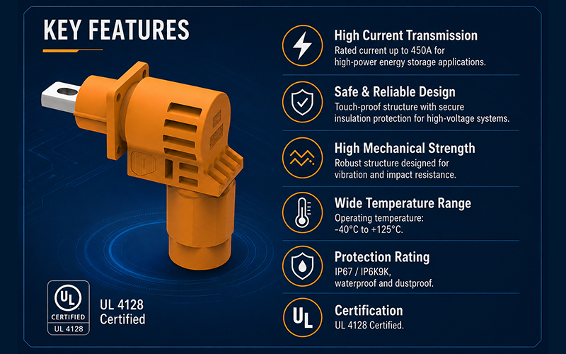
Representative samples of FPIC’s energy storage connector series were evaluated by UL to UL 4128 for electrochemical battery system applications. The UL documentation identifies the series under category BBTH2, with certificate number UL-US-26118764-0 and report reference E533832-20260524, issued on May 25, 2026.
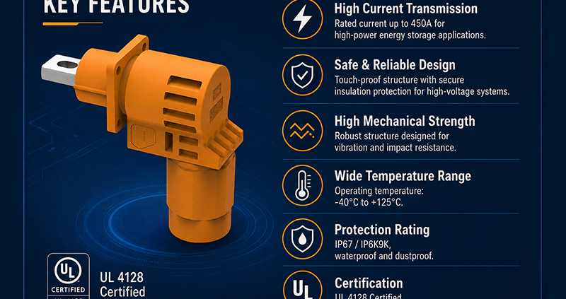
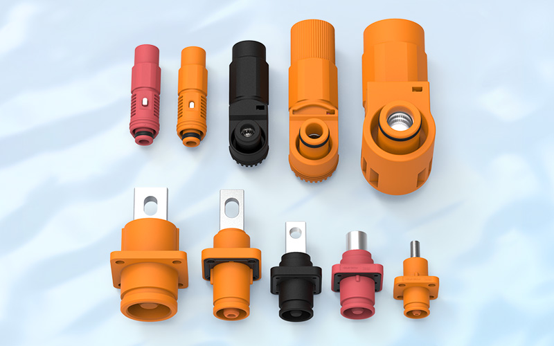
The evaluated series includes insulated, single-pole cable connectors and panel-mounted inlets rated 2000V DC and 450A. For the cable-connector configuration, the evaluated conductor size is 300 kcmil. The panel-mounted versions are intended for factory assembly to suitable copper conductors or copper/copper-alloy busbars in battery equipment.
- The scope and limitations are equally important:
- the products are UL Recognized Components, not complete end-use equipment;
- they are not suitable for disconnecting under load;
- the evaluated products are intended for use within complete equipment;
- the FPIC report states that they were not investigated for an environmental rating or for use outside an equipment enclosure;
- acceptability must be determined in the final application.
This recognition gives BESS engineers a verified component-level reference for a 2000V, 450A intercell/intertier connection. It should not be interpreted as blanket approval for every cable, enclosure, ambient condition, or storage-system design.
A Practical Checklist Before Specifying the Connection
Before requesting a sample or quotation, define the actual operating envelope rather than providing only a voltage and current target. FPIC’s separate guide on selecting a 2000V 450A BESS connector provides additional product-screening questions.
- Electrical requirements: nominal voltage, maximum continuous DC voltage, transient conditions, continuous current, peak current, and duty cycle.
- Conductor interface: cable size and construction, busbar material and thickness, terminal temperature rating, and preferred termination method.
- Thermal environment: cabinet ambient temperature, cooling method, neighboring heat sources, mounting orientation, and allowable temperature rise.
- Installation conditions: indoor or outdoor location, enclosure protection, altitude, pollution, condensation, chemical exposure, vibration, and shock.
- Safety functions: polarity, mechanical keying, touch protection, locking, service isolation, and any high-voltage interlock requirement.
- Compliance route: target country, component standard, end-equipment standard, marking requirement, and certification-body expectations.
- Project inputs: drawings, 2D/3D files, cable specifications, mating layout, samples, forecast volume, and development schedule.
This information allows the connector, cable, termination, and installation method to be reviewed together. It also prevents a nominal rating from being applied outside the configuration in which it was verified.
Conclusion: 2000V Creates an Opportunity—and a Higher Design Burden
The main advantage of a 2000V BESS architecture is straightforward: more power can be transmitted with less current, or more power can be carried at the same current. This can reduce current-related losses and may simplify some conductor paths.
The engineering burden rises at the same time. Insulation coordination, creepage and clearance, material behavior, contact resistance, cable matching, service procedures, protection devices, and complete-system validation all require closer control.
FPIC’s 2000V 450A UL Recognized connector series provides a verified component option for defined electrochemical battery equipment applications. Explore FPIC’s broader energy storage connector range or request a custom connector evaluation using your maximum operating voltage, load profile, cable or busbar details, installation environment, drawings, and target compliance requirements.
Discuss your BESS interconnection project: info@fpiconn.com
FAQ
1.Does a 2000V architecture automatically make a BESS more efficient?
No. Higher voltage reduces current at the same power, which can lower resistive losses, but actual efficiency also depends on the PCS, conductors, connectors, cooling, topology, and operating profile.
2.How much does current decrease when moving from 1500V to 2000V?
Current decreases by 25% at the same power. For an ideal 1 MW DC path, current changes from approximately 666.7A at 1500V to 500A at 2000V.
3.Can a 1500V connector be used in a 2000V battery system?
No. A connection is limited by its lowest-rated component. The connector, cable, protection devices, busbars, and related equipment must all be suitable for the system’s maximum voltage and applicable transient conditions.
4.Does a 450A rating apply to every cable size and ambient temperature?
No. Current capability depends on the evaluated conductor, termination, ambient temperature, enclosure, cooling, duty cycle, and applicable derating. FPIC’s UL-evaluated cable-connector configuration uses a 300 kcmil conductor.
5.Is UL 4128 recognition the same as certification of a complete BESS?
No. UL 4128 addresses the defined intercell/intertier connector component. The complete energy storage system must be evaluated under the applicable end-equipment and installation requirements.
6.Can the FPIC connector be disconnected while current is flowing?
No. The UL documentation states that the recognized connector is not suitable for disconnecting under load. The equipment must provide an appropriate isolation and service procedure.
Resources
- CATL: TENER Sodium Energy Storage System and 2000V Upgrade Path, June 22, 2026.
- Amphenol Industrial Operations: TS1 High-Voltage, High-Current Connector, December 2025.
- Amphenol Industrial Operations: H4 Plus P2KV 2000V Expansion, August 20, 2026.
- IEC 60664-1:2020 — Insulation Coordination for Low-Voltage Supply Systems, including Amendment 1:2025.
- UL Standards & Engagement: UL 4128, Edition 6, published June 16, 2026.
- UL Solutions: Energy Storage System Testing and UL 9540 Certification.