Tag Archive for: high-voltage connectors

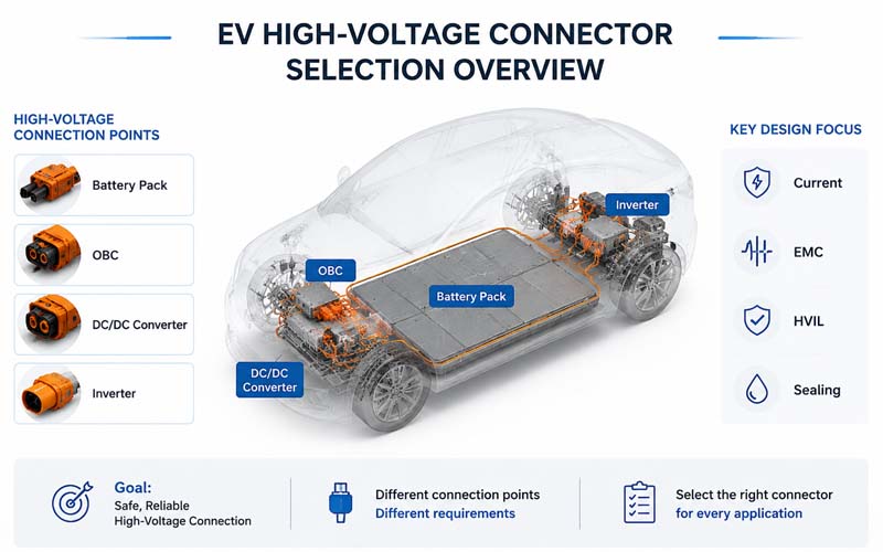
EV High-Voltage Connector Selection Overview

High-voltage connectors are critical interfaces in electric vehicles (EVs), battery energy storage systems (ESS), and industrial electrification platforms.

They connect major subsystems such as:

  • battery packs
  • onboard chargers (OBC)
  • DC/DC converters
  • inverters
  • power distribution units (PDU)

Although these connectors may appear similar, each application has distinct electrical, mechanical, thermal, and EMC requirements.

This article explains how engineers can select the right high-voltage connector for battery pack, OBC, and DC/DC interfaces.
EV High-Voltage Connector Selection Overview


Step 1: Define Electrical Requirements

The first step is to establish the electrical operating conditions.

Key parameters include:

  • nominal and maximum voltage
  • continuous current
  • peak current
  • allowable temperature rise
  • insulation resistance requirements
  • dielectric withstand requirements

For example:

  • Battery pack connectors may carry several hundred amps.
  • OBC connectors typically carry lower current but may require excellent shielding.
  • DC/DC connectors often combine high current and compact packaging.

Step 2: Evaluate Safety Requirements

High-voltage connectors must meet electrical safety expectations such as:

  • creepage and clearance distances
  • touch-safe design
  • HVIL integration
  • CPA locking features
  • ingress protection

Safety requirements depend on standards, OEM specifications, and application risk assessments.


Step 3: Consider Mechanical Packaging

Packaging constraints strongly influence connector selection.

Important factors include:

  • available installation space
  • cable bend radius
  • mating access
  • keying and polarization
  • mounting method

Compact designs often require trade-offs between size and performance.


Step 4: Assess Environmental Conditions

Connectors must survive the real operating environment.

Consider:

  • temperature range
  • vibration
  • humidity
  • salt exposure
  • dust and water ingress
  • chemical exposure

Battery pack connectors usually require high sealing performance.


Step 5: Review EMC and Shielding Needs

Applications near switching power electronics may require:

  • shielded cable interfaces
  • 360° shield termination
  • conductive backshells
  • low-impedance grounding

OBC and DC/DC interfaces are especially sensitive to EMC requirements.


Step 6: Confirm Current Carrying Capability

Current rating should be validated using:

  • conductor size
  • terminal design
  • contact resistance
  • thermal rise testing
  • cooling conditions

Do not rely solely on catalog current ratings.


Step 7: Evaluate Contact Technology

Important considerations include:

  • contact material
  • plating system
  • contact normal force
  • resistance stability

Reliable low-resistance performance is essential for high-current applications.


Step 8: Determine HVIL Requirements

Many EV systems require integrated HVIL circuits.

HVIL is commonly used in:

  • battery pack connectors
  • service disconnects
  • OBC interfaces

Verify interlock sequencing and connector compatibility.


Step 9: Consider Serviceability

Field maintenance may require:

  • easy disconnect
  • visual mating confirmation
  • ergonomic locking mechanisms
  • replacement without removing adjacent components

Serviceability is particularly important for battery packs.


Step 10: Validate Supplier Capability

Evaluate whether the supplier can provide:

  • application engineering support
  • prototype samples
  • custom cable assemblies
  • validation reports
  • PPAP documentation
  • production traceability

Supplier capability is as important as connector specifications.


Typical Priorities by Application

Battery Pack Connectors

Primary concerns:

  • high current capacity
  • HVIL
  • sealing
  • vibration resistance
  • serviceability

OBC Connectors

Primary concerns:

  • EMC shielding
  • compact size
  • thermal performance

DC/DC Connectors

Primary concerns:

  • current density
  • packaging
  • shielding
  • temperature performance

Common Selection Mistakes

Choosing Based Only on Current Rating

Thermal and environmental performance must also be verified.

Ignoring Shield Termination

Can create EMC problems.

Overlooking Service Access

May complicate maintenance.

Underestimating Packaging Constraints

Can lead to late redesign.

Not Defining Validation Requirements Early

Delays supplier qualification.


Validation Tests to Request

Typical validation activities include:

  • temperature rise
  • contact resistance
  • vibration
  • thermal cycling
  • sealing tests
  • HiPot and insulation resistance
  • HVIL functional testing
  • EMC testing

How FPIC Supports High-Voltage Connector Selection

FPIC provides custom high-voltage connectors and cable assemblies for EV, ESS, and industrial systems.

Our engineering support includes:

  • application analysis
  • connector selection
  • HVIL integration
  • shielding design
  • prototype development
  • validation testing

We help customers balance safety, EMC performance, packaging, and cost.


Final Thoughts

Selecting the right high-voltage connector requires a system-level view.

Engineers should consider:

  • electrical requirements
  • insulation design
  • shielding
  • environmental exposure
  • serviceability
  • supplier capability

A well-chosen connector improves reliability, safety, and manufacturability across the entire product lifecycle.


FAQ

What is the most important factor when selecting a high-voltage connector?

There is no single factor. Voltage, current, safety, environment, and packaging must all be considered.

Do all EV high-voltage connectors require HVIL?

Not all, but HVIL is widely used for safety-critical interfaces.

Why is shielding important for OBC connectors?

OBC systems generate switching noise that can affect EMC performance.

Can catalog current ratings be used directly?

They should be verified under actual operating conditions.

What validation tests are typically required?

Temperature rise, vibration, sealing, HiPot, and HVIL functional testing.


Selecting High-Voltage Connectors for Your EV or ESS Project?

FPIC provides engineering support and custom high-voltage connector and cable assembly solutions for battery packs, OBCs, and DC/DC converters.

Contact us to discuss your application requirements.


Resources

  1. ISO 6469 – Safety Specifications for Electrically Propelled Vehicles
    Core safety requirements for EV high-voltage systems.
  2. LV215 / LV214 Automotive High-Voltage Connector Standards
    Requirements for high-voltage connectors and cable assemblies.
  3. USCAR-2 – Automotive Connector Performance Specification
    Environmental and electrical validation methods.
  4. TE Connectivity – EV High Voltage Connector Selection Guide
    Practical guidance for subsystem connector selection.
  5. Molex – EV Power Connectivity Solutions
    Connector technologies for battery and power electronics.
Creepage vs Clearance Overview

In high-voltage connectors design, electrical safety depends on much more than conductor size and insulation thickness.

Two of the most fundamental design parameters are creepage distance and clearance distance.

These dimensions determine how effectively a connector can withstand operating voltage, transients, humidity, contamination, and aging without flashover or tracking.

Whether you are designing connectors for electric vehicles (EVs), battery energy storage systems (ESS), charging equipment, or industrial power electronics, understanding creepage and clearance is essential.

This article explains the basic concepts, design rules, and validation considerations engineers should know.


What Is Clearance?

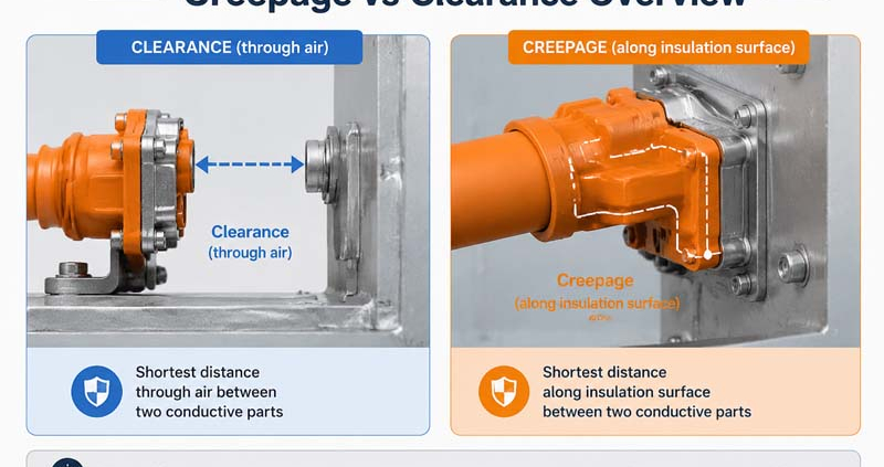
Clearance is the shortest distance through air between two conductive parts at different electrical potentials.

Examples include:

  • adjacent terminals
  • terminal to shield
  • terminal to connector shell
  • live parts to chassis ground

If clearance is insufficient, arcing may occur during voltage transients or at high altitude.


What Is Creepage?

Creepage is the shortest path along the surface of an insulating material between two conductive parts.

This path follows the connector housing rather than passing directly through air.

Insufficient creepage can lead to:

  • surface tracking
  • carbonization
  • insulation degradation
  • eventual electrical failure
  • Creepage vs Clearance Overview

Why Both Distances Matter

Clearance addresses air breakdown risk.

Creepage addresses surface leakage and contamination risk.

Both must meet applicable standards and application-specific requirements.


Factors Affecting Required Distances

Required creepage and clearance depend on several variables.

Operating Voltage

Higher voltage requires larger separation distances.

Transient Overvoltage

Switching events and fault conditions may create voltages significantly above nominal levels.

Pollution Degree

Defines the expected environmental contamination level.

Typical classifications:

  • Pollution Degree 1: controlled indoor environment
  • Pollution Degree 2: light non-conductive contamination
  • Pollution Degree 3: conductive contamination or condensation

Material Group (CTI)

Comparative Tracking Index (CTI) measures resistance to surface tracking.

Higher CTI materials can permit shorter creepage distances.

Altitude

Air insulation strength decreases as altitude increases, often requiring increased clearance.

Safety Standard Requirements

Applicable standards may define minimum distances and correction factors.


How Connector Designers Increase Creepage Distance

Design techniques include:

  • insulating ribs
  • barriers
  • recessed terminals
  • tortuous surface paths
  • optimized terminal orientation

These features increase surface distance without significantly enlarging connector size.


Clearance Optimization Techniques

Methods to improve clearance include:

  • wider terminal spacing
  • insulation walls
  • shield isolation
  • careful tolerance control

3D CAD analysis is often used to verify minimum distances.


Common Design Mistakes

Using Nominal Dimensions Only

Manufacturing tolerances may reduce actual distances.

Ignoring Contamination

Real-world environments can be more severe than expected.

Overlooking Altitude

Reduced air density lowers dielectric strength.

Neglecting Aging

Materials may degrade over time.

Assuming Creepage and Clearance Are Interchangeable

They address different failure mechanisms.


Example Applications

Typical high-voltage connector applications include:

  • EV battery pack connectors
  • inverter interfaces
  • onboard chargers
  • DC fast charging connectors
  • ESS battery interconnects

Each application may have unique safety requirements.


Validation Methods

Design assumptions should be verified by:

  • dielectric withstand (HiPot) testing
  • insulation resistance measurement
  • humidity conditioning
  • contamination testing
  • thermal cycling
  • altitude testing where applicable

Validation confirms that theoretical spacing performs under real conditions.


Relevant Standards

Common standards include:

  • IEC 60664-1
  • IEC 62109
  • IEC 61800
  • UL 840
  • ISO 6469
  • OEM high-voltage specifications

The applicable standard depends on the end product and market.


Practical Design Trade-Offs

Increasing creepage and clearance generally improves safety, but may also:

  • enlarge connector size
  • increase material cost
  • affect mating force
  • complicate packaging

The goal is to meet requirements efficiently while preserving manufacturability.


How FPIC Supports High-Voltage Connector Development

FPIC designs and manufactures high-voltage connectors and cable assemblies for EV, ESS, and industrial systems.

Our engineering support includes:

  • creepage and clearance review
  • material selection guidance
  • HVIL integration
  • sealing and shielding design
  • HiPot and insulation testing

We help customers balance electrical safety, packaging, and cost.


Final Thoughts

Creepage and clearance are foundational elements of high-voltage connector design.

A robust design must consider:

  • voltage level
  • environmental conditions
  • insulation material properties
  • tolerances
  • applicable standards

Understanding these principles early helps prevent costly redesigns and improves product safety.


FAQ

What is the difference between creepage and clearance?

Clearance is distance through air; creepage is distance along an insulating surface.

Why is CTI important?

Higher CTI materials resist tracking better and may allow shorter creepage distances.

Does altitude affect connector design?

Yes. Higher altitude reduces dielectric strength of air, increasing required clearance.

Can barriers increase creepage distance?

Yes. Ribs and barriers create longer surface paths.

How are these distances verified?

Through CAD analysis and electrical validation testing such as HiPot.


Designing a High-Voltage Connector?

FPIC provides engineering support and manufacturing for custom high-voltage connectors and cable assemblies with optimized insulation design and validated performance.

Contact us to discuss your application requirements.


Resources

  1. IEC 60664-1 – Insulation Coordination for Low-Voltage Systems
    Core standard for creepage and clearance requirements.
  2. UL 840 – Insulation Coordination Including Clearances and Creepage Distances
    North American guidance for electrical spacing.
  3. ISO 6469 – EV Safety Requirements
    Safety specifications for electrically propelled vehicles.
  4. TE Connectivity – High Voltage Connector Design Guide
    Practical connector design considerations.
  5. Molex – High-Voltage Connectivity Solutions
    Application guidance for EV and energy systems.