
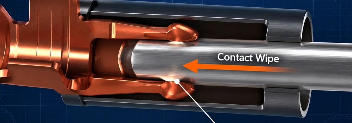
Connector contact wipe is the relative sliding of mating surfaces while they are pressed together during engagement. This motion can disrupt surface films and help establish conductive contact spots. Its effectiveness depends on the finish, contact geometry, and applied load—not distance alone.
For an engineer reviewing a terminal drawing, the useful questions are practical: Where do the surfaces first touch? How far do they slide under load? Where does the contact finally rest? And will that sequence still work at the limits of the assembly tolerances?
What Is Contact Wipe?
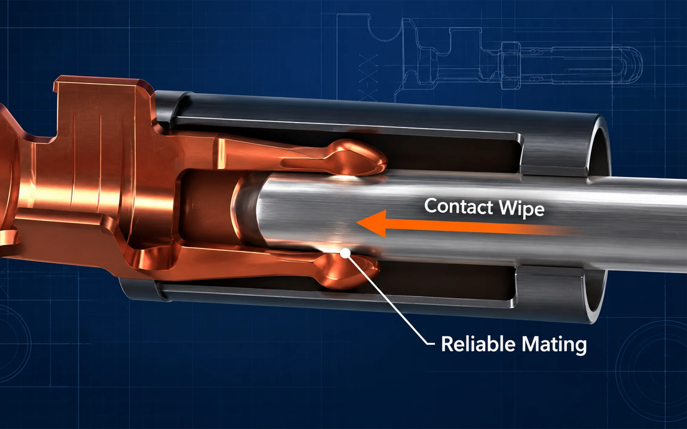
In a typical pin-and-socket interface, the pin begins to touch a spring contact before the connector reaches its final mated position. Continued insertion creates sliding between the contacting surfaces. That sliding is the wiping action.
The relevant distance is the travel at the contact interface. It is not automatically the entire housing insertion stroke. A connector may move some distance before its conductive surfaces touch.
Samtec’s technical explanation of contact wipe connects this action with surface-film disruption and highlights the importance of insertion depth, board spacing, and assembly tolerances.
| Term | What It Describes | Design Question |
|---|---|---|
| Wipe distance | Relative sliding travel at the loaded contact interface | Is the intended contact track traversed? |
| Normal force | Load perpendicular to the local mating surface | Is adequate load maintained during engagement and service? |
| Mating stroke | Movement of the connector halves during assembly | When does electrical contact begin within that movement? |
| Mated overlap | Engagement remaining at the final position | Does the interface remain properly engaged across the allowed assembly range? |
These dimensions and forces are related, but a drawing should define them separately. A supplier’s definition of insertion depth or engagement length should also be checked before it is used as a wipe specification.
How Sliding Helps Disrupt Surface Films
An electrical contact operates through microscopic conducting regions. Oxide and contamination films can obstruct those regions even when two metal parts appear to be touching. Contact-mechanics research explains how surface roughness and films influence resistance at the interface. Persson, 2022
During engagement, local pressure and sliding can work together to fracture or displace films. The outcome depends on what covers the surface and on the contact system itself. Wiping should therefore be understood as a designed interface action, not a guarantee that a connector cleans away every contaminant.
Tin and gold illustrate why the surface finish matters. Tin forms an oxide film in air; properly designed tin interfaces use contact load and sliding to establish electrical contact through that film. Gold is resistant to oxidation and generally supports different force and travel requirements. Samtec discusses these distinctions in its plating selection guidance.
For a custom project, define the expected surface condition before selecting the travel. Storage, handling, assembly residues, and service exposure should be part of that discussion. Heavy contamination or damaged plating calls for investigation rather than repeated mating as a production remedy.
Contact Wipe and Contact Resistance
A useful wiping action can help establish a lower-resistance interface when films are obstructing conduction. However, there is no universal equation that converts a particular travel distance into a guaranteed resistance value.
The measured result also depends on contact load, surface condition, material, and the arrangement of the conducting spots. Moreover, a measurement taken across a connector assembly may include conductor and termination resistance in addition to the separable interface. Wiping does not correct a defective crimp or solder joint.
For design comparison, specify consistent measurement locations and sample preparation. Otherwise, differences attributed to the contact track may actually come from the fixture or another part of the current path.
IEC 60512-2-1 provides a millivolt-level contact-resistance measurement method. The product specification must still define the applicable limits and conditioning. A basic continuity result answers whether a path exists; it does not establish the resistance margin or predict durability.
How Terminal Geometry Determines the Sliding Path
Review the interface in successive positions, rather than only as a fully mated CAD section. The lead-in, spring profile, mating-pin dimensions, and final stop determine how engagement develops. Materion’s insertion-force analysis shows why contact location, angle, and load change as a pin enters a spring contact.
For a new terminal design, the following review sequence helps turn the concept into drawing requirements:
- Identify first touch. Locate the initial contact point for the specified mating counterpart.
- Follow the loaded path. Check how the contact point and spring deflection change during insertion.
- Locate final seating. Confirm where the interface rests when the assembly reaches its approved mated position.
- Compare the path with the finish specification. Check the specified contact zone and transitions between finishes.
- Repeat at dimensional limits. Review the allowed variation in both connector halves and their mounting arrangement.
For automotive connector systems, include terminal seating and housing engagement in this review. For board-to-board connectors, use the installed board arrangement, including the permitted board spacing and alignment.
A Practical Tolerance Example
Consider a hypothetical pair of PCB connectors. The nominal CAD assembly shows a contact track with comfortable engagement. In the installed product, the board spacing reaches its upper permitted limit while a mating terminal reaches the short end of its tolerance. The contact may engage later than it does in the nominal model.
The design-review question is whether sufficient loaded travel and final engagement remain in that combination. At the opposite dimensional extreme, check spring deflection and mechanical clearance as well.
This is an illustrative review scenario, not FPIC test data. It shows why a nominal travel dimension alone cannot establish the suitability of a finished assembly.
Plating Wear and Excessive Wipe
The same sliding that helps condition an interface also exposes the finish to friction and wear. Extending the track should therefore be evaluated against the required number of mating operations and the condition of the contact surfaces afterward.
A useful specification identifies the mating finish, underplate, thickness requirements, and designated contact area. “Gold plated” or “tin plated” alone leaves too much undefined for a durability comparison. Samtec’s plating guidance treats finish selection as a balance among electrical behavior, operating life, and application requirements.
For a development review, ask:
- Does the mating pair use the approved finish combination?
- Is the final contact position within the specified contact zone at every allowed assembly condition?
- Does the durability test represent production finishes and any specified lubricant?
- Are wear tracks, resistance changes, and mating force assessed together?
- If the travel is increased, what evidence shows the revised interface still meets its life requirement?
A visible track is evidence of sliding, not automatically evidence of failure. It also does not prove acceptable remaining plating. Interpret the track against the drawing, inspection criteria, and electrical results.
Vibration and Micro-Movement Are a Different Problem
The intended sliding during assembly and repeated movement during service require separate consideration. Small oscillatory motion at a loaded interface can produce fretting damage; oxidation of susceptible surfaces and wear debris can contribute to deteriorating electrical contact.
The engineering literature identifies contact load, motion, temperature, and interface design as relevant variables. Braunovic’s review of fretting in electrical connections also discusses the value of connection design and lubrication in reducing its effects.
A connector that establishes a satisfactory interface during insertion must still preserve it in service. For design review, consider housing support, board mounting, terminal restraint, and cable loading alongside the contact system. If lubrication is proposed, qualify it for the actual materials and environment.
Do not treat additional insertion travel as evidence that vibration testing is unnecessary. The two address different stages of the connector’s life.
Why Wipe and Normal Force Must Be Designed Together
Travel describes the movement; normal force describes the perpendicular load during that movement. Effective engagement requires a suitable combination of both, with the surface finish included in the decision.
As Materion explains, contact angle and force can vary during insertion. The final seated load therefore does not describe every point along the path. Spring material must also retain suitable force through the required operating life. Materion technical analysis
Review the pair as a system:
| Design Condition to Investigate | Question for Validation |
|---|---|
| Travel available, but low load along part of the path | Does the interface establish acceptable resistance under the specified surface condition? |
| Adequate seated load, but limited sliding before seating | Does the design still meet its initial and conditioned electrical requirements? |
| High load combined with substantial sliding | Are mating effort and surface wear acceptable over the required cycles? |
| Acceptable nominal geometry, but reduced engagement at tolerance limits | Does the installed assembly retain the required performance margin? |
The companion topic, contact normal force, examines spring loading and retained force. This article adds the path taken to reach the final electrical contact position. Both belong in the same interface review.
How to Validate the Design
Use the applicable product and customer specifications to establish the test sequence. The following is a planning framework, not a universal qualification procedure.
| Review or Test | Evidence to Collect | Question It Helps Answer |
|---|---|---|
| Mated geometry and tolerance review | First-touch position, loaded travel, seated position, assembly limits | Does the intended path exist in the actual assembly? |
| Material and finish verification | Approved alloy, finish system, thickness and contact-zone records | Do samples represent the proposed production design? |
| Baseline electrical measurement | Resistance measured at defined points | Is initial electrical performance within specification? |
| Mechanical operation | Specified mating cycles, force observations, post-cycle inspection | How does repeated engagement affect the interface? |
| Environmental conditioning | Exposure and measurements specified for the application | Does performance remain acceptable after the relevant aging conditions? |
| Dynamic testing | Applicable vibration or shock conditions and electrical monitoring | Does the mated assembly remain stable during movement? |
| Final examination | Electrical results, wear observations, dimensional or mechanical findings | Which mechanism explains any change? |
IEC 60512-9-1 addresses mechanical operation. IEC 60512-6-4 addresses sinusoidal vibration. These method references do not establish one minimum wipe distance or one acceptance limit for all connectors.
Record whether samples were unmated before a post-test measurement. Another mating operation changes the surface history and can complicate interpretation of the conditioned interface. Follow the specified sequence and keep sample handling traceable.
For procurement, request the approved mating drawing and qualification scope together with the electrical specification. A resistance value without the associated counterpart, assembly condition, and conditioning history provides limited evidence for a new application.
From Terminal Design to Production Control
For custom automotive and PCB projects, FPIC’s R&D capabilities connect terminal structure and material review with tooling, prototype validation, and project-specific testing. Relevant manufacturing work includes precision stamping, molding, and assembly, with dimensional and finish verification supporting the approved design.
The practical starting point is a mating-pair drawing, the installed assembly limits, finish requirements, operating environment, and expected mating cycles. These inputs help define what needs to be reviewed and demonstrated before production approval.
Conclusion
Reliable mating depends on a controlled contact path, a suitable finish, and sufficient load throughout engagement and service. Specify the sliding action as part of the complete interface, then validate its electrical and mechanical behavior across tolerances and the required life.
For a custom terminal or connector design review, send the mating drawings and application requirements to info@fpiconn.com.
Frequently Asked Questions
Is wipe distance the same as connector insertion depth?
Not necessarily. The housings can travel before the conductive surfaces first touch. Use the product drawing’s defined reference points to distinguish insertion depth, loaded sliding travel, and final overlap.
Is a longer wiping path always better?
No. Evaluate the travel together with load, finish, assembly tolerances, and required mating life. A change should be supported by electrical and durability results rather than length alone.
Do gold-plated contacts still need a defined mating path?
Yes. Gold’s resistance to oxidation does not remove the need to control engagement, surface condition, and wear. The required movement is specific to the contact design.
What is the minimum acceptable distance?
There is no single value applicable to every connector. Use the mating-pair specification and validation results for the particular geometry, finish, loading, and application.
Does wiping during insertion prevent fretting in service?
It does not establish fretting immunity. Initial engagement and repeated micro-movement in service are different conditions and should be evaluated separately.
What should an OEM provide for a custom terminal review?
Provide both mating-part drawings, mounting and engagement limits, material and finish specifications, current and temperature requirements, environmental exposure, expected mating cycles, and the applicable qualification requirements.
Resources
- Samtec, Is Contact Wipe Important?, published July 23, 2025; page also displays June 4, 2026.
- B. N. J. Persson, On the Electric Contact Resistance, Tribology Letters, July 20, 2022.
- Samtec, What Plating Option Is Best For My Connector?, published October 19, 2017; page also displays January 17, 2025.
- Materion, How Can Connector Insertion Force Be Reduced?, January 1, 2024.
- Milenko Braunovic, Fretting in Electrical/Electronic Connections: A Review, IEICE Transactions on Electronics, August 1, 2009. Public abstract and bibliographic record.
- IEC, IEC 60512-2-1:2002 — Contact Resistance, Millivolt Level Method.
- IEC, IEC 60512-9-1:2010 — Mechanical Operation.
- IEC, IEC 60512-6-4:2002 — Vibration, Sinusoidal.