
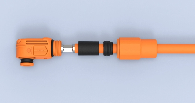
High-current connector selection often starts with one number: the rated current.
A customer may see “450A” on a product specification and reasonably assume that the connector can continuously carry 450A in any equipment environment.
That assumption can be dangerous.
Quick Answer:
Temperature rise in a high-current connector depends on current, contact resistance, conductor size, terminal design, material, ambient temperature, installation conditions, and heat dissipation. A 450A rating only applies under defined test conditions; actual continuous current may need to be reduced when ambient temperature or thermal loading increases.
That is why high-current connector engineering should focus not only on current rating, but also on thermal performance under real operating conditions.
Why High-Current Connectors Generate Heat
Every electrical connection has resistance.
Even when that resistance is very small, current passing through the interface generates heat.
The basic relationship is:
Power loss = I² × R
This is one of the most important relationships in high-current connector design.
If current doubles while resistance remains unchanged, the heat generated by resistive losses increases by a factor of four.
That means a resistance change that seems insignificant at 10A may become important at 300A or 450A.
For example, heat can develop at:
- contact interfaces;
- crimp connections;
- busbar interfaces;
- conductor transitions;
- cable terminals;
- bolted connections.
The goal is therefore not simply to achieve low resistance at the initial test.
The contact system must maintain low and stable resistance throughout its service life.
Contact Resistance Is One of the Main Heat Sources
Contact resistance is created where two conductive surfaces touch.
In a high-current connector, this usually occurs between the plug and receptacle terminals.
The resistance depends on several factors:
- contact geometry;
- effective contact area;
- normal contact force;
- surface roughness;
- terminal material;
- plating material;
- contamination;
- wear;
- corrosion;
- mating cycles.
A well-designed terminal provides sufficient contact pressure to maintain a stable conductive path.
If contact pressure becomes too low, resistance may rise.
This can lead to:
Higher resistance → More heat → Faster material degradation → Even higher resistance
That cycle can become a long-term reliability risk.
TE describes low contact resistance as one reason its high-power connector designs can reduce temperature rise and power loss. Molex similarly links low contact resistance with lower voltage drop and lower heat generation in its high-current COEUR-based interconnects.
Terminal Material Influences Thermal Performance
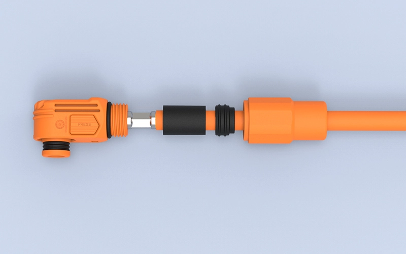
Terminal material must provide both electrical conductivity and mechanical stability.
Typical high-current connector contacts use copper or copper-alloy materials.
Pure copper offers excellent conductivity, but connector terminals also require mechanical properties such as:
- strength;
- spring stability;
- formability;
- fatigue resistance;
- resistance to stress relaxation.
Depending on the terminal structure, manufacturers may therefore use different copper alloys to balance conductivity and mechanical performance.
Common options include:
- high-conductivity copper;
- brass;
- phosphor bronze;
- copper-nickel-silicon alloys;
- other high-conductivity copper alloys.
FPIC’s internal connector materials identify alloys such as C7025, C7035, and C18400 as suitable options for higher-current applications because they provide a useful combination of conductivity and mechanical properties.
Material choice should therefore be based on both electrical and mechanical requirements.
Plating Also Affects Contact Stability
The base terminal material is only one part of the contact system.
The contact surface may use plating such as:
- tin;
- silver;
- gold;
- nickel underlayers.
For high-current power applications, silver plating is commonly used because of its conductivity and contact performance.
Tin can also be suitable in many applications, although friction, fretting, oxidation, temperature, and mating-cycle requirements must be considered.
The plating system affects:
- contact resistance;
- corrosion resistance;
- wear;
- friction;
- temperature stability;
- service life.
The correct plating is therefore determined by the application rather than by choosing the most expensive material.
Cable Cross-Section Directly Affects Temperature Rise
A connector cannot be evaluated independently from its cable.
The resistance of a conductor depends on:
Material resistivity × conductor length ÷ conductor cross-sectional area
In practical terms:
A smaller conductor generally has greater resistance and produces more heat under the same current.
This is why connector specifications normally define compatible cable sizes.
For example, a high-current interface might be designed around conductor sizes such as:
- 35 mm²;
- 50 mm²;
- 70 mm²;
- 95 mm²;
- 120 mm²;
- 150 mm².
The cable cross-section must match both:
- the required current capacity; and
- the terminal crimp or termination design.
Phoenix Contact provides a useful example: the same connector can have different permissible currents depending on whether it is used with 2.5 mm², 4 mm², or 6 mm² conductors. Its published derating example shows that conductor size and ambient temperature both materially change the usable current.
Crimp Quality Can Become a Hidden Heat Source
Even when the connector and cable are correctly sized, poor termination can create additional resistance.
For a crimped connection, engineers must control:
- crimp height;
- crimp width;
- conductor position;
- conductor compression;
- strand damage;
- bellmouth;
- terminal deformation;
- pull-out force.
A poor crimp can create:
- insufficient conductor contact;
- uneven current distribution;
- localized resistance;
- localized heating.
FPIC’s terminal crimping standards therefore treat crimp height as one of the most important production controls and also use pull-force and cross-section analysis to verify termination quality.
For high-current connectors, termination quality is part of thermal management.
Ambient Temperature Changes the Available Thermal Margin
Connector temperature is not determined by self-heating alone.
The final operating temperature is approximately influenced by:
Ambient temperature + temperature rise caused by current
This means the same connector may behave differently in:
- a 25°C laboratory;
- a 40°C industrial cabinet;
- a 55°C BESS cabinet;
- an outdoor enclosure exposed to solar heating.
If a connector housing or cable insulation has a maximum permitted operating temperature, higher ambient temperature leaves less room for self-heating.
Phoenix Contact describes current-carrying capacity as dependent on both self-heating and ambient temperature, and its derating curves show permissible current decreasing as ambient temperature rises.
This is why high-current connector selection should include a current-temperature derating curve, not only one headline ampere value.
Continuous Current Is More Important Than Short Peak Current
A connector may experience several types of current:
- continuous operating current;
- short peak current;
- startup current;
- overload current;
- pulse current.
These loads do not create the same thermal effect.
A short-duration peak may not allow enough time for the complete connector assembly to reach thermal equilibrium.
Continuous current is different.
When current flows for a long period, the connector continues heating until the generated heat and dissipated heat reach equilibrium.
For BESS applications, this distinction is particularly important because energy storage systems can operate under sustained charging or discharging conditions.
Therefore, the engineering question should not only be:
What is the maximum current?
It should also be:
How long will that current flow?
Why “Rated 450A” Does Not Mean 450A Everywhere
This is the most important point of the article.
A current rating is normally determined under specified test conditions.
Those conditions can include:
- ambient temperature;
- conductor size;
- conductor length;
- contact configuration;
- mounting arrangement;
- temperature-rise limit;
- airflow;
- measurement location.
TE explicitly states that its published current ratings represent maximum continuous current under defined or optimum conditions and that derating factors must be applied for higher ambient temperature and multiple loaded circuits.
IEC 60512-5-1 defines a standardized method for evaluating connector temperature rise under current load, while IEC 60512-5-2 addresses current-temperature derating at elevated ambient temperatures.
Therefore:
450A means:
The connector has demonstrated a defined current-carrying capability under specified conditions.
It does not mean:
The connector can operate continuously at 450A in every enclosure, cable configuration, temperature, altitude, or cooling condition.
That distinction should always be explained clearly to customers.
Multiple Loaded Contacts Can Change Current Capacity
For multi-contact connectors, another factor appears: mutual heating.
When multiple adjacent contacts carry current simultaneously, each contact contributes heat to the connector housing.
This raises the internal temperature and can reduce the current that each contact can safely carry.
TE notes that the current capacity per contact decreases when multiple contacts are simultaneously used for power transmission.
This means engineers must define:
- how many contacts carry current;
- current per contact;
- spacing between contacts;
- conductor sizes;
- enclosure temperature.
A single-contact rating cannot simply be multiplied by the number of contacts.
Connector Housing Material Sets Another Thermal Limit
The terminal is not the only component exposed to heat.
The housing, seals, cable insulation, and nearby materials also have temperature limits.
Typical connector housing materials include:
- PA66;
- PBT;
- LCP;
- PA6T;
- PA9T;
- PPS.
Different polymers provide different:
- heat resistance;
- mechanical strength;
- moisture absorption;
- dimensional stability;
- flame performance.
FPIC’s internal engineering materials identify high-temperature materials such as LCP, PA9T, PA6T, PA46, and PPS for connector designs that must withstand elevated-temperature processes such as reflow soldering.
The thermal limit of the complete system should therefore reflect the lowest critical material limit, not only the copper contact.
High-Voltage BESS Cabinets Create More Difficult Thermal Conditions
Energy storage systems are a particularly relevant example.
Inside a BESS cabinet, multiple heat sources may exist:
- battery modules;
- busbars;
- contactors;
- fuses;
- high-current connectors;
- power conversion equipment;
- cable bundles.
The cabinet itself may also have restricted airflow.
This means the connector operates within a larger thermal system.
Engineers must consider:
- cabinet ambient temperature;
- cable bundle temperature;
- neighboring components;
- ventilation;
- cooling system design;
- continuous charge/discharge profile.
For this reason, the connector temperature should ideally be evaluated inside a representative system environment rather than only through a catalog value.
Temperature Rise Testing Provides the Evidence
Temperature-rise testing helps determine how much the connector heats when current passes through it.
A typical test process includes:
- assemble the connector with the specified conductor;
- place temperature sensors at defined measurement points;
- record initial ambient and component temperature;
- apply the test current;
- wait until thermal equilibrium;
- record the maximum temperature;
- calculate the temperature rise;
- repeat at different current levels if required.
IEC 60512-5-1 specifically defines a test method for assessing current-carrying capability based on connector temperature rise.
The resulting data can then help generate a current-temperature derating curve.
What FPIC Tests During High-Current Validation
FPIC has dedicated equipment for connector electrical and thermal validation.
Our internal laboratory capability includes:
- temperature-rise testers;
- contact-impedance testers;
- withstand-voltage testers;
- insulation-resistance testing;
- insertion and extraction force testing;
- vibration testing;
- thermal-shock chambers;
- X-ray inspection;
- dimensional inspection.
FPIC’s equipment list includes multiple temperature-rise testers and contact-impedance instruments, supporting validation of high-current connector and cable-assembly performance.
For high-current projects, the validation plan can evaluate:
- connector temperature rise;
- terminal resistance;
- cable temperature;
- crimp condition;
- interface stability;
- mechanical reliability.
Applying This to FPIC’s 2000V 450A Connector
FPIC’s high-current energy storage connector portfolio includes 2000V / 450A solutions for battery-system applications.
But the correct engineering message is not:
“450A can always be used continuously.”
The more technically credible message is:
The 450A platform is designed and validated for high-current energy storage applications under defined conditions, and final current capability should be confirmed against conductor size, ambient temperature, installation environment, and system thermal requirements.
This distinction strengthens rather than weakens the product story.
It tells engineers that FPIC understands how current ratings actually work.
For BESS customers, FPIC can support project evaluation based on:
- system voltage;
- continuous and peak current;
- cable cross-section;
- connector mounting;
- ambient temperature;
- cabinet cooling;
- duty cycle;
- required temperature-rise limit.
This moves the discussion from catalog selling to engineering selection support.
High-Current Connector and Cable Assembly Must Be Evaluated Together
For high-current systems, the connector and cable assembly form one electrical and thermal path.
The evaluation should include:
| Component | Key thermal factors |
| Contact | Material, geometry, resistance, plating |
| Terminal | Crimp structure and conductor interface |
| Cable | Cross-section, material, length, insulation |
| Connector housing | Temperature capability and heat dissipation |
| Busbar interface | Surface area, contact pressure, resistance |
| Cabinet | Ambient temperature and airflow |
| Load | Continuous current, peak current, duty cycle |
Ignoring any one of these factors can produce an incomplete thermal assessment.
A Practical High-Current Connector Selection Checklist
Before selecting a high-current connector, provide the following data:
Electrical Requirements
- nominal voltage;
- maximum voltage;
- continuous current;
- peak current;
- peak duration;
- duty cycle.
Cable Requirements
- conductor material;
- conductor cross-section;
- cable outer diameter;
- insulation temperature rating.
Thermal Environment
- minimum and maximum ambient temperature;
- enclosure temperature;
- airflow;
- cooling method;
- nearby heat sources.
Mechanical Installation
- panel mount or cable mount;
- busbar connection;
- cable orientation;
- available space.
Validation Requirements
- permitted temperature rise;
- test current;
- test duration;
- applicable IEC, UL, or customer standards.
Providing this information allows engineers to evaluate the real usable current, not simply repeat the catalog rating.
Frequently Asked Questions
1. What causes temperature rise in a connector?
Temperature rise primarily comes from electrical resistance in contacts, terminals, crimps, conductors, and interfaces while current is flowing.
2. Does lower contact resistance reduce temperature rise?
Generally yes. Lower resistance reduces resistive power loss at a given current, assuming the rest of the thermal system remains unchanged.
3. Does a larger cable always reduce connector temperature?
A larger conductor usually reduces cable resistance and can improve heat conduction away from the interface, but connector geometry, terminal design, ambient temperature, and installation conditions must still be evaluated.
4. Can a 450A connector continuously carry 450A?
Only under the conditions for which the current rating has been established. Higher ambient temperature, different conductor sizes, restricted cooling, or other installation factors may require derating.
5. Why is temperature-rise testing important?
It verifies how the complete connector assembly behaves under current load and helps determine whether the contact, terminal, housing, and cable remain within permitted temperature limits.
6. What is a connector derating curve?
A derating curve shows how permissible current decreases as ambient temperature increases. It provides a more realistic selection tool than a single rated-current number.
Conclusion
Current rating alone does not define high-current connector performance.
Temperature rise depends on the complete electrical and thermal system:
current + resistance + conductor + material + ambient temperature + installation + duty cycle
For BESS and other high-power systems, this is why a 450A connector should be evaluated as part of the complete application rather than treated as an isolated 450A component.
FPIC supports high-current connector and cable-assembly projects with connector development, conductor and terminal matching, temperature-rise testing, contact-resistance measurement, prototype validation, and repeat-production quality control.
Discuss Your High-Current Connector Project
FPIC supports high-voltage and high-current interconnection development for BESS, battery systems, industrial equipment, and customized power applications.
Email: info@fpiconn.com
Resources
- IEC. IEC 60512-5-1:2002 – Connectors for Electronic Equipment – Current-Carrying Capacity Tests – Temperature Rise.
- IEC. IEC 60512-5-2:2002 – Connectors for Electronic Equipment – Current-Temperature Derating.
- TE Connectivity. Battery Pack Connectors – Current Carrying Capacity, T-Rise and Derating.
- TE Connectivity. Power Connectivity – Current Rating and Derating Guidance.
- Phoenix Contact. Electrical Tests for Connectors – Current Carrying Capacity and Derating.
- Molex. SW1 High-Current Interconnects and COEUR Socket Technology.