Plastic mold design standardization reduces rework, shortens lead time, improves interchangeability, and makes mass production more stable. For engineering teams, it is not just a documentation exercise. It is a practical system for mold bases, side actions, runners, gates, locating features, and ejection structures.
If you want faster mold development and more predictable molding results, standardize five things first: the mold base platform, movement structures, runner and gate logic, locating features, and ejection design. That approach helps engineering teams reduce variation, simplify purchasing, improve maintenance, and make quality more repeatable from prototype to mass production.
Below is a practical guide built from FPIC’s internal engineering standard and aligned with widely accepted industry thinking. It is written for buyers, product engineers, and mold teams who want better control over cost, quality, and launch timing.
What Plastic Mold Design Standardization Really Means
Plastic mold design standardization means using defined rules for mold platforms, standard components, structural calculations, gating logic, locating methods, and ejection choices instead of redesigning every detail from scratch. In practice, this shortens design cycles, improves repeatability, and makes molds easier to build, inspect, repair, and scale across product families.
That industry logic is consistent with FPIC’s internal engineering presentation, which starts standardization with mold-base selection, preferred materials, ordering rules, datum logic, and standard machining expectations before moving into side actions, runners, locating, and ejection.
Why Standardization Pays Off
Standardization is valuable because mold performance depends on many linked decisions. A well-defined mold base platform makes procurement and machining more predictable. Standard side-action rules reduce assembly risk. Balanced runner logic helps filling consistency. Repeatable ejection rules reduce part damage and maintenance time.
For companies serving automotive, medical, industrial, and connector programs, this matters even more. Product families often share similar geometries, tolerance expectations, and validation paths. A standardized mold design approach makes design reviews faster and engineering decisions easier to reuse.
Faster Engineering Decisions
When design rules are already clear, engineers spend less time debating routine choices and more time solving real product-specific challenges.
Better Manufacturing Consistency
Standard platforms and structures reduce dimensional variation, simplify machining, and improve assembly accuracy.
Easier Mold Maintenance
A mold built on standard logic is easier to inspect, repair, and modify during long production runs.
Start with a Standard Mold Base Strategy
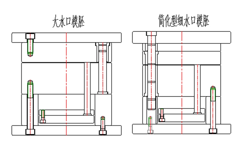
FPIC’s engineering standard identifies two common mold-base types: a large sprue mold base and a simplified pin-point gate mold base. It also specifies common reference suppliers, mold-base material in the S50C–S55C range, and common core materials such as S136, SKD61, DC53, and VIKING. The same internal standard also requires chamfering of machined edges, default dimensioning from the datum corner unless otherwise stated, and standardized ordering logic for mold-base sizes and plate thicknesses.
Why the Mold Base Matters
The mold base is the structural foundation of the tool. A standardized base improves rigidity, purchasing efficiency, and machining predictability.
Material Selection Should Not Be Arbitrary
Mold-base and core material choices directly affect wear resistance, heat treatment stability, polishing behavior, and maintenance cycles.
Standard Ordering Reduces Errors
Using a consistent ordering format for mold-base size, plate thickness, and supplier requirements reduces communication mistakes and speeds up purchasing.
Standardize Movement Structures Before They Become Problems
Slides, hydraulic side actions, first-return mechanisms, and lifters are common failure points when teams rush concept work. FPIC’s engineering standard gives clear rules here: slide geometry follows defined angular relationships, hydraulic cylinders must not be used to seal off plastic directly, first-return mechanisms are required when ejectors sit under moving members, and lifter angles are generally kept in the 3°–10° range while ensuring no interference with surrounding parts or the molded product.
Slide Design Should Follow Fixed Geometry Rules
Slide systems work best when angular relationships, guide structures, and clearance rules are standardized early.
Hydraulic Structures Need Safety Logic
Hydraulic cylinders can add flexibility, but they also introduce sealing and timing risks if used incorrectly.
Lifter Design Must Balance Motion and Part Safety
Lifters must avoid interference with both the product and neighboring components, while also preventing scraping or plastic damage during ejection.
Treat Runner and Gate Design as a System
FPIC’s internal standard treats the gating system as a structured decision set. It defines nozzle-to-sprue relationships, locating-ring use, runner cross-section choices, runner layout logic, and gate selection guidance. It specifically notes that round and trapezoidal runners are both common, that multi-cavity runner layouts should prioritize balanced filling, that H-shaped distribution generally gives better balance than T-shaped layouts, and that different gate types serve different production goals.
Runner Geometry Affects More Than Flow
Runner shape and size influence pressure drop, thermal loss, filling balance, and cycle stability.
Gate Selection Should Match the Product Goal
Submarine gates support automation. Large sprues are simple but often manual. Pin gates improve automatic separation but raise mold complexity.
Balanced Layouts Improve Multi-Cavity Stability
A balanced runner system helps ensure that all cavities fill more consistently, reducing quality variation between parts.
Make Locating Features Do More Than Just Align Parts
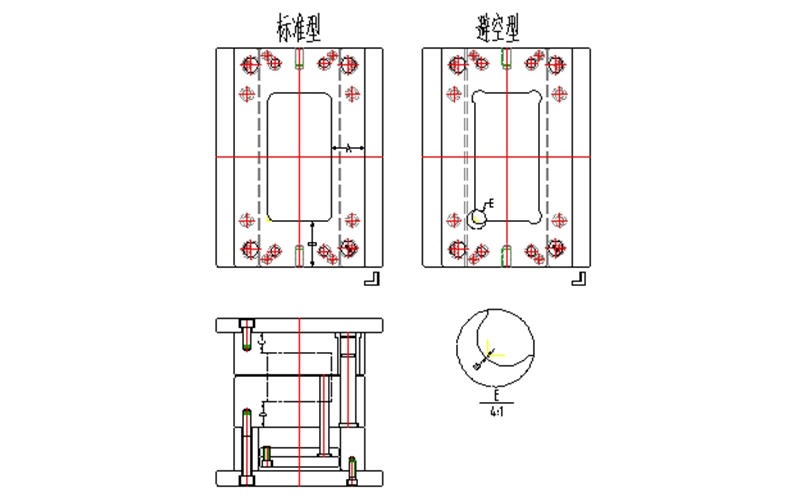
A good mold does not rely on memory. It relies on features that prevent mistakes. FPIC’s internal standard makes this clear by treating locating structures as a core method to prevent assembly errors and preserve mold precision. It also recommends insert-level locating to prevent rotation or incorrect assembly, and it uses anti-error design when a part is not center-symmetric or when left/right variants exist.
Mold Accuracy Starts with Repeatable Positioning
Stable locating improves assembly precision and reduces accumulated tolerance errors inside the tool.
Anti-Mistake Design Saves Real Cost
Simple anti-error structures can prevent reversed assembly, insert rotation, and rework during tool build or maintenance.
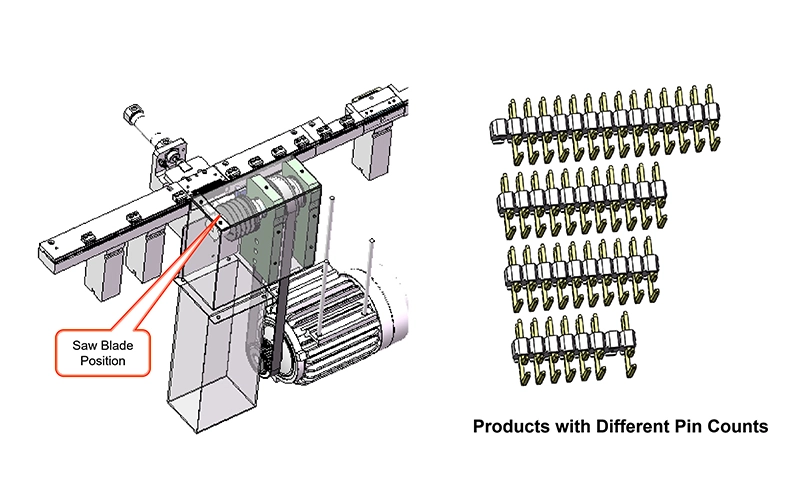
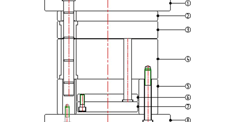
Ejection Rules Should Protect Parts and Tool Life
Ejection design is another area where standardization saves money quickly. FPIC’s internal standard prioritizes ejector placement near ribs or high-release-force areas, requires enough distance between water channels and ejector pins, encourages fewer ejector-pin size variations in a single tool, and defines when to switch from pins to sleeve ejection, push blocks, or stripper plates. It also calls for vent grooves in sleeve ejectors to reduce thermal friction and wear.
Ejector Pins Are Not Always the Best Answer
Pins are efficient, but deep bosses, thin walls, and cosmetic surfaces may require sleeves, push blocks, or stripper plates.
Standard Pin Layout Rules Improve Stability
Uniform pin placement and limited pin-size variation simplify machining, assembly, and future maintenance.
Venting and Clearance Protect the Tool
Vent grooves and proper spacing reduce friction, sticking, and heat-related wear during long production runs.
A Practical 5-Step Standardization Framework
If you want to build or upgrade your own plastic mold design standardization system, use this sequence:
Step 1 – Lock the Platform
Define preferred mold-base families, suppliers, base materials, and standard machining scope.
Step 2 – Lock the Motion Rules
Standardize slide, cylinder, first-return, and lifter geometry before detailed 3D work starts.
Step 3 – Lock the Flow Logic
Create a gating decision table by resin, part size, cosmetic requirement, and automation goal.
Step 4 – Lock Locating and Mistake-Proofing
Use consistent locating features for mold bases, inserts, and asymmetrical parts.
Step 5 – Lock the Ejection Decision Tree
Define when to use pins, sleeves, blocks, and stripper plates, plus spacing and venting rules.
This is the point where standardization stops being a document and starts becoming a productivity tool.
What Buyers and Product Engineers Should Ask Mold Suppliers
If you are outsourcing tooling, ask these five questions before approving design freeze:
- Do you use a standard mold-base system?
- How do you standardize slides, lifters, and hydraulic side actions?
- How do you choose runner layout and gate type for this resin and part geometry?
- What locating features prevent assembly mistakes and insert rotation?
- What is your standard ejection strategy for ribs, deep bosses, and cosmetic surfaces?
A supplier that answers clearly is more likely to control risk later.
Where FPIC Adds Value
At FPIC, we view mold design standardization as part of product quality, not just tooling efficiency. That matters for connector programs, precision plastic parts, and complex assemblies where dimensional consistency, cosmetic control, and repeatable mass production all matter. Our internal engineering standard covers mold-base selection, side-action logic, runner and gate decisions, locating, and ejection in a structured way, and it is supported by our broader manufacturing focus on automation, process discipline, and scalable production.
We do not recommend over-standardizing blindly. Some parts need exceptions. But a good standard should make exceptions visible and intentional. That is usually the difference between a mold that merely works and a mold that works predictably over time.
If you are developing precision plastic parts, connector components, or custom tooling programs, FPIC can support manufacturability review, tooling optimization, and scalable production planning.
Conclusion
Plastic mold design standardization is one of the fastest ways to improve tooling quality without adding unnecessary complexity. Done well, it reduces variation, accelerates design reviews, improves maintainability, and supports more stable mass production.
If you are evaluating a new tooling partner or trying to improve internal mold performance, start with the five areas above. If you need support on precision plastic parts, connector tooling, or manufacturability review, FPIC’s engineering and manufacturing teams can help you move from concept to stable production with fewer surprises.
References / Notes
- FPIC internal engineering presentation: R&D Dept., compiled by Zhu Xiaolong, 2026.04.14. This article incorporates FPIC’s internal design rules for mold bases, side actions, runners, locating, and ejection.
- HASCO, Specifications for Injection Moulds 2.0 and HASCO standard mold-unit information.
- DME, official mold-base, mold-component, CAD, and technical-guide resources.
- Protolabs Network (formerly Hubs), Injection Molding Design Guide.
- Ma et al., research on standard component libraries for plastic injection mold design.
- Mold-Masters, discussion of runner balance and shear effects.