
Designing a connector is not only about achieving the highest electrical performance.
A connector must also be:
- Easy to manufacture
- Consistent in mass production
- Cost-effective
- Reliable throughout its service life
Many connector designs fail to consider manufacturing requirements early enough.
The result can include:
- Complex assembly processes
- Higher tooling costs
- Production delays
- Difficult quality control
- Increased unit cost
This is why Design for Manufacturing (DFM) plays an important role in connector development.
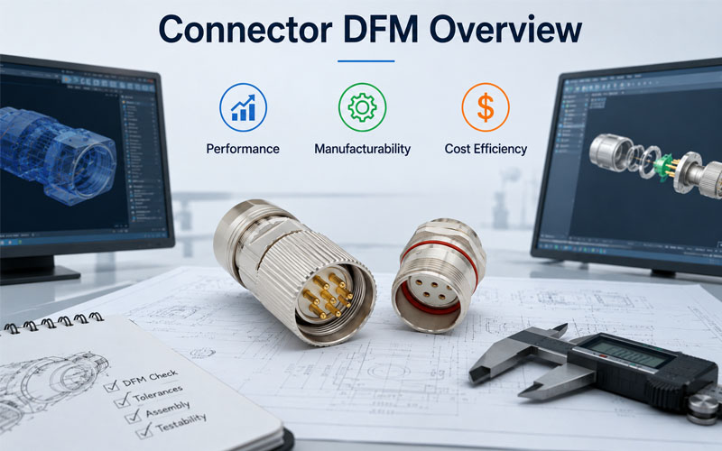
A successful connector design balances three key factors:
Performance + Manufacturability + Cost
What Is Connector DFM?
Connector DFM (Design for Manufacturing) is an engineering approach that considers production requirements during the design stage.
Instead of designing a connector first and solving manufacturing problems later, DFM integrates:
- Material selection
- Tooling requirements
- Assembly processes
- Testing methods
- Production scalability
from the beginning.
The goal is to create a connector that performs well while remaining practical for high-volume manufacturing.
Why DFM Matters in Connector Development
A connector may perform well in a laboratory environment but face challenges during mass production.
Common issues caused by poor DFM include:
❌ Difficult assembly
❌ Tight manufacturing tolerances
❌ High tooling complexity
❌ Low production yield
❌ Increased inspection requirements
❌ Higher manufacturing cost
A DFM-focused design reduces these risks by considering the entire product lifecycle.
1.Design for Electrical Performance
The first priority of any connector is reliable electrical performance.
DFM does not mean reducing performance.
Instead, it means achieving required performance with an optimized design.
Key electrical considerations include:
Contact System Design
The contact structure affects:
- Current capacity
- Contact resistance
- Mating cycles
- Signal integrity
Engineers should evaluate:
✔ Contact geometry
✔ Contact force
✔ Material selection
✔ Plating thickness
✔ Current path design
A well-designed contact system improves reliability while avoiding unnecessary material costs.
Creepage and Clearance Design
For higher voltage applications, spacing requirements are critical.
Proper DFM considers:
- Insulation distance
- Housing structure
- Manufacturing capability
Over-designing spacing may increase connector size and cost.
Under-designing may create safety risks.
The goal is the correct balance.
2.Design for Manufacturability
A connector designed for manufacturing should support stable and efficient production.
Important factors include:
Simplify Connector Structure
Complex structures increase:
- Mold difficulty
- Assembly steps
- Failure risks
Good DFM practices include:
✔ Reducing unnecessary components
✔ Simplifying assembly direction
✔ Minimizing manual operations
✔ Improving part consistency
Optimize Housing Design
The connector housing must consider injection molding requirements.
Important factors:
- Wall thickness
- Draft angles
- Rib design
- Shrinkage control
- Mold release
Poor housing design can lead to:
- Warpage
- Cracks
- Dimensional variation
Improve Assembly Efficiency
Mass production requires repeatable assembly.
Design considerations:
✔ Easy terminal insertion
✔ Clear orientation features
✔ Locking mechanism feedback
✔ Error-proof assembly
These features reduce production errors and improve efficiency.
3.Material Selection for DFM
Material selection affects both performance and manufacturing cost.
Important factors include:
- Temperature resistance
- Mechanical strength
- Chemical resistance
- Processing requirements
Common connector materials:
Housing Materials
PA (Polyamide)
Advantages:
✔ Good mechanical strength
✔ Cost-effective
✔ Widely available
PBT
Advantages:
✔ Dimensional stability
✔ Good electrical insulation
PPS
Advantages:
✔ High temperature performance
✔ Excellent chemical resistance
The right material depends on the application requirements.
Contact Materials
Common choices:
- Copper alloys
- Phosphor bronze
- Beryllium copper
Selection depends on:
- Conductivity
- Spring performance
- Mating cycles
- Cost targets
4.Design for Tooling Efficiency
Connector tooling can represent a significant development investment.
DFM helps reduce tooling complexity.
Key considerations:
Mold Design
Good connector designs consider:
✔ Fewer sliders
✔ Simple parting lines
✔ Stable cavity design
✔ Easy maintenance
Terminal Stamping Design
Terminal design affects:
- Material usage
- Stamping speed
- Production consistency
Optimized terminal geometry can reduce:
- Material waste
- Processing cost
- Defect rates
5.Balancing Performance and Cost
The lowest-cost connector is not always the most economical solution.
A cheaper connector may create:
- Higher failure risk
- More maintenance
- Increased warranty costs
Effective cost optimization focuses on:
Right Specification
Avoid unnecessary features.
Example:
Not every application requires:
- Premium plating
- Extreme temperature materials
- Maximum mating cycles
Production Efficiency
Reduce cost through:
✔ Better tooling design
✔ Automated assembly
✔ Higher yield
✔ Reduced inspection time
Lifecycle Cost
A reliable connector can reduce:
- Downtime
- Replacement costs
- Field failures
The best design optimizes total value, not only unit price.
6.DFM Review Process for Connector Development
A typical connector DFM review includes:
Step 1: Requirement Analysis
Evaluate:
- Electrical requirements
- Mechanical conditions
- Environmental exposure
- Cost targets
Step 2: Design Review
Check:
- Structure
- Materials
- Tolerances
- Assembly method
Step 3: Manufacturing Evaluation
Review:
- Mold feasibility
- Stamping process
- Automation possibility
- Testing requirements
Step 4: Prototype Validation
Perform:
- Dimensional inspection
- Electrical testing
- Mechanical testing
- Environmental testing
Step 5: Mass Production Optimization
Monitor:
- Yield
- Process stability
- Quality data
- Cost performance
How FPIC Applies DFM Principles to Connector Development
FPIC supports customers from connector concept development to mass production.
Our engineering approach considers:
- Application requirements
- Connector structure
- Material selection
- Tooling feasibility
- Assembly efficiency
- Quality validation
Through DFM-driven development, FPIC helps customers achieve connectors that are:
✔ Reliable
✔ Manufacturable
✔ Cost-efficient
✔ Ready for mass production
Final Thoughts
A successful connector design requires more than excellent technical specifications.
The best connector balances:
- Electrical performance
- Mechanical reliability
- Manufacturing efficiency
- Cost control
By applying DFM principles early, engineers can reduce development risks, improve production consistency, and create products that perform reliably in real-world applications.
Good connector design begins before production starts.
FAQ
What does DFM mean in connector design?
DFM means Design for Manufacturing, an approach that optimizes connector design for efficient and reliable production.
Why is DFM important for connectors?
DFM reduces manufacturing problems, improves production yield, lowers cost, and helps ensure consistent quality.
Does DFM reduce connector performance?
No. Proper DFM achieves the required performance while improving manufacturability and cost efficiency.
What factors should be considered during connector DFM?
Engineers should consider materials, tooling, assembly process, tolerances, testing, and production requirements.
When should DFM review happen?
DFM should begin during the early connector design stage before tooling and mass production.
Need a Connector Designed for Mass Production?
FPIC provides customized connector solutions with engineering support from design optimization to volume manufacturing.
With experience in connector development, tooling coordination, assembly, and testing, FPIC helps OEM customers create reliable and production-ready connector solutions.
Contact FPIC today to discuss your connector development project.
Resources
- IEC 60512 – Connectors for Electronic Equipment – Tests and Measurements
https://www.iec.ch/
Connector testing methods for electrical and mechanical performance evaluation. - IPC/WHMA-A-620 – Requirements and Acceptance for Cable and Wire Harness Assemblies
https://www.ipc.org/
Industry requirements for cable and harness manufacturing quality. - ISO 9001 Quality Management Systems
https://www.iso.org/iso-9001-quality-management.html
Quality management principles supporting consistent manufacturing processes. - IATF 16949 Automotive Quality Management System
https://www.iatfglobaloversight.org/
Automotive quality requirements focused on process control and defect prevention.