
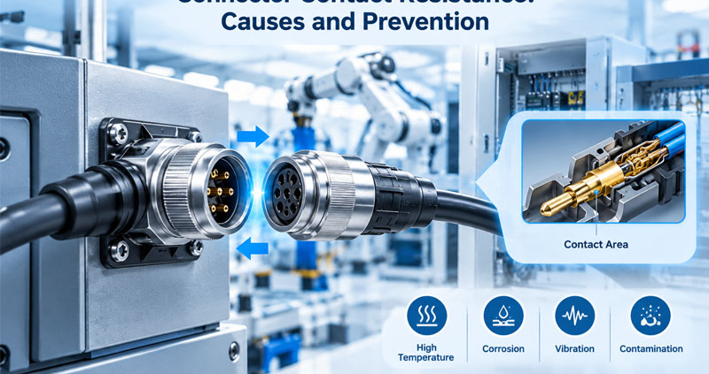
Connector contact resistance is a critical electrical parameter that directly affects the reliability and efficiency of an electrical connection.
An ideal connector should provide a stable, low-resistance path between mating conductors. In real applications, however, the actual contact area is much smaller than the apparent physical contact area. Surface roughness, contact force, plating condition, contamination, vibration, temperature, and mechanical deformation can all influence the resistance of the connection.
When contact resistance increases, electrical losses and localized heating increase as well. The relationship can be expressed as:
P = I²R
where P is power loss, I is current, and R is contact resistance.
This becomes particularly important in high-current connectors, automotive systems, industrial automation equipment, energy storage systems, and other applications where connectors must operate reliably under continuous electrical and mechanical stress.
Understanding what causes contact resistance to increase—and how to prevent it—is therefore an important part of connector design and validation.
1.What Is Connector Contact Resistance?
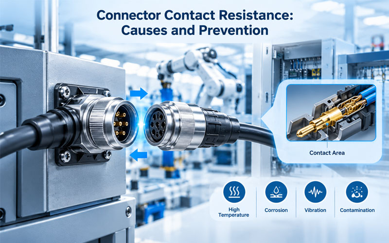
Connector contact resistance is the electrical resistance introduced at the interface between two mating conductive surfaces.
It is different from the resistance of the wire itself.
A simplified connection can be considered as:
Wire → Crimp → Terminal → Mating Contact → Terminal → Crimp → Wire
Each interface contributes to the overall electrical performance.
The mating contact is particularly important because two metal surfaces do not actually touch across their entire apparent area. Microscopic surface irregularities create localized conductive contact points known as asperities.
The effective electrical contact area is therefore much smaller than the visible mechanical contact area.
This is why contact force, surface condition, material selection, and plating have such a significant influence on connector resistance.
2.Why Low and Stable Contact Resistance Matters
Low contact resistance is important, but stable contact resistance over the connector’s service life is even more important.
A connector may initially show excellent electrical performance but experience increasing resistance after:
- Repeated mating cycles
- Vibration
- Thermal cycling
- Humidity exposure
- Corrosion
- High-current operation
- Mechanical deformation
- Surface wear
Increasing resistance can lead to several problems.
Electrical losses
Higher resistance increases voltage drop:
V = I × R
In low-voltage systems, even a small voltage drop can become significant.
Heat generation
Because:
P = I²R
heat generation increases rapidly as current rises.
For example, if current doubles, the resistive heating increases by approximately four times for the same resistance.
Accelerated degradation
Local heating can affect:
- Contact plating
- Terminal spring properties
- Connector housing
- Insulation
- Sealing materials
This can create a feedback loop in which electrical degradation leads to additional thermal and mechanical degradation.
3.Contact Force and Contact Resistance
Contact force is one of the most important design factors affecting connector contact resistance.
When mating contacts are pressed together, sufficient force helps establish stable conductive contact points and break through surface films or contamination.
However, simply increasing contact force is not always the correct solution.
Excessive contact force can cause:
- Higher insertion force
- Difficult mating
- Increased wear
- Terminal deformation
- Reduced connector service life
The objective is therefore to establish an appropriate contact-force window rather than maximizing force.
Important design factors include:
- Contact geometry
- Spring characteristics
- Terminal material
- Plating system
- Contact wipe
- Mating cycles
- Required insertion force
A well-designed contact system should maintain adequate force throughout the expected operating life.
4.Contact Plating and Surface Condition
The contact surface plays a major role in electrical stability.
Common contact materials and plating systems are selected based on requirements such as:
- Electrical conductivity
- Corrosion resistance
- Wear resistance
- Mating frequency
- Environmental exposure
- Current level
Gold plating is commonly used where stable low-level electrical performance and corrosion resistance are important.
Tin plating can provide a practical solution for many applications, particularly where cost and current-carrying requirements are important.
However, plating selection should always be considered together with the contact geometry, environment, mating cycles, and application requirements.
Plating failure mechanisms
Contact resistance can increase when the surface experiences:
- Wear-through
- Oxidation
- Corrosion
- Plating porosity
- Contamination
- Mechanical damage
The correct plating system is therefore not simply a material-selection decision. It is part of the overall contact reliability strategy.
5.Fretting Corrosion and Vibration
Vibration can cause microscopic movement between mating contacts.
Although the movement may be too small to notice visually, repeated micro-motion can damage the contact surface.
This phenomenon is commonly associated with fretting corrosion.
A typical progression is:
Vibration → Micro-Motion → Surface Wear → Oxidation/Contamination → Increased Resistance
The problem can be especially challenging because a connector may pass a static resistance test while experiencing intermittent resistance changes during actual vibration.
Prevention strategies
Depending on the application, engineers can consider:
- Appropriate contact force
- Stable terminal retention
- Suitable plating
- Connector locking
- Mechanical support
- Cable strain relief
- Vibration-resistant mounting
For vibration-sensitive systems, electrical monitoring during mechanical testing can provide more useful information than measuring resistance only before and after the test.
6.Crimp Quality Directly Affects Resistance
The contact interface is not the only resistance-sensitive area.
The wire-to-terminal crimp is another critical electrical connection.
A poor crimp can produce:
- Higher resistance
- Localized heating
- Mechanical weakness
- Intermittent electrical performance
Common causes include:
- Incorrect crimp height
- Wrong tooling
- Improper conductor positioning
- Incomplete wire insertion
- Damaged conductor strands
- Incorrect terminal-wire combination
How to control crimp resistance
Production quality control can include:
- Crimp height measurement
- Crimp force monitoring
- Pull-force testing
- Cross-section inspection
- Electrical resistance testing
This is especially important for high-current and high-reliability cable assemblies.
7.Contamination and Oxidation
Even a well-designed contact system can experience resistance increases if the mating interface becomes contaminated.
Potential contaminants include:
- Dust
- Oil
- Moisture
- Chemical residues
- Oxidation products
- Assembly debris
Contamination can reduce the effective conductive area and interfere with stable metal-to-metal contact.
Environmental conditions therefore need to be considered during connector selection.
For outdoor or harsh industrial applications, engineers may need to evaluate:
- Sealing
- IP protection
- Plating
- Housing material
- Environmental compatibility
- Corrosion resistance
8.Connector Overheating and Thermal Runaway
High contact resistance is closely related to connector temperature rise.
Consider a high-current connection carrying 100 A.
If contact resistance is:
R = 1 mΩ
then:
P = 100² × 0.001 = 10 W
That means the contact interface is generating approximately 10 W of heat at that resistance.
If resistance increases to:
R = 2 mΩ
the heat generation becomes:
P = 100² × 0.002 = 20 W
The electrical loss has doubled.
This demonstrates why small changes in resistance can have a significant effect in high-current applications.
Thermal design should consider:
- Current level
- Number of energized contacts
- Contact resistance
- Ambient temperature
- Duty cycle
- Wire size
- Connector housing
- Heat dissipation
- Installation conditions
Connector current ratings should therefore not be considered independently from the actual system conditions.
9.Mating Cycles and Contact Wear
Every mating and unmating operation can cause mechanical movement at the contact interface.
The contact surfaces may experience:
- Sliding
- Wiping
- Friction
- Plating wear
- Spring deformation
After repeated cycles, the original surface condition may change.
For applications requiring frequent connection and disconnection, engineers should evaluate:
- Rated mating cycles
- Contact plating
- Contact force
- Wiping action
- Wear resistance
- Contact resistance after cycling
A connector should be validated against the actual expected service profile rather than relying solely on an initial resistance measurement.
10.Temperature Effects on Contact Resistance
Temperature can influence both electrical and mechanical properties.
As temperature changes, materials can expand and contract, affecting:
- Contact dimensions
- Contact force
- Terminal alignment
- Housing geometry
- Plating interfaces
- Crimp connections
High temperatures can also accelerate material aging and surface degradation.
Low temperatures may influence material flexibility and contact mechanics.
For connectors operating across wide temperature ranges, thermal cycling should therefore be included in reliability validation.
11.Connector Geometry and Current Distribution
Contact resistance is not determined by material alone.
The geometry of the contact system also matters.
Important design variables include:
- Contact beam shape
- Contact area
- Contact normal force
- Current path length
- Terminal thickness
- Contact alignment
- Mating depth
- Current distribution
For high-current applications, engineers need to consider how current flows through the complete terminal system rather than focusing only on the nominal contact area.
Poor geometry can create localized current concentration and thermal hotspots.
12.How to Measure Connector Contact Resistance
Accurate contact resistance measurement requires an appropriate test method.
For very low resistance values, ordinary two-wire measurements can be affected significantly by:
- Test lead resistance
- Connection resistance
- Instrument limitations
A four-wire Kelvin measurement can provide better accuracy for low-resistance measurements because the current and voltage measurement paths are separated.
A simplified test arrangement is:
Current Source → Connector → Current Return
while separate sensing leads measure the voltage drop directly across the contact interface.
The resistance can then be calculated using:
R = V / I
Measurement consistency matters
Testing should define:
- Test current
- Test voltage
- Measurement location
- Mating condition
- Stabilization time
- Temperature
- Number of samples
- Acceptance criteria
Without consistent test conditions, resistance results may be difficult to compare.
13.Contact Resistance Testing During Reliability Validation
Initial resistance testing is only one part of connector validation.
A more useful strategy is to measure contact resistance at different stages.
For example:
Initial Measurement
↓
Mating Cycle Test
↓
Vibration Test
↓
Thermal Cycling
↓
Environmental Exposure
↓
Final Resistance Measurement
For demanding applications, electrical performance can also be monitored during mechanical or environmental testing.
This helps identify intermittent changes that may not be visible in a simple before-and-after measurement.
14.Common Connector Contact Resistance Problems
| Problem | Likely Cause | Potential Solution |
|---|---|---|
| Initial resistance too high | Poor contact geometry | Optimize terminal design |
| Resistance increases after cycling | Contact wear | Review plating and contact force |
| Resistance fluctuates during vibration | Fretting | Improve retention and contact stability |
| Resistance rises at high current | Thermal stress | Optimize current capacity and thermal design |
| High wire-to-terminal resistance | Poor crimp | Improve tooling and process control |
| Resistance increases in humid environments | Corrosion | Improve sealing and plating |
| Different samples show large variation | Process variation | Strengthen dimensional and electrical controls |
| Localized terminal heating | Current concentration | Review contact geometry and current path |
15.How to Prevent High Connector Contact Resistance
Preventing contact resistance problems requires cooperation between electrical, mechanical, material, and manufacturing design.
1.Optimize contact geometry
Design the contact system to maintain stable force and current distribution.
2.Select suitable plating
Match the plating system to electrical requirements, mating cycles, and environmental exposure.
3.Control crimp quality
Use controlled tooling, dimensional inspection, and appropriate mechanical and electrical verification.
4.Protect the contact interface
Use appropriate sealing and environmental protection for the application.
5.Control mechanical movement
Minimize vibration-induced micro-motion through proper locking, retention, mounting, and strain relief.
6.Validate under realistic conditions
Combine contact resistance testing with mating cycles, vibration, thermal cycling, and environmental exposure where applicable.
7.Monitor manufacturing variation
Stable connector performance requires stable production processes.
16.Design Considerations for High-Current Connectors
High-current applications are particularly sensitive to contact resistance.
Examples include:
- Energy storage systems
- Battery systems
- Industrial power equipment
- Power distribution
- Automotive electrical systems
- Inverters
- Power conversion equipment
In these applications, engineers should evaluate the entire current path:
Cable → Crimp → Terminal → Contact Interface → Terminal → Crimp → Cable
A low-resistance contact interface cannot compensate for a poor crimp or undersized conductor.
The complete assembly therefore needs to be designed as one electrical and thermal system.
17.Manufacturing Controls for Stable Contact Resistance
For mass production, the challenge is not only achieving low resistance on one sample.
The objective is to maintain consistent performance across large production volumes.
Important controls may include:
- Terminal dimensional inspection
- Contact-force verification
- Plating inspection
- Crimp-height control
- Crimp-force monitoring
- Pull-force testing
- Automated continuity testing
- Contact resistance testing
- Visual inspection
- Traceability
Process data can help identify gradual changes before they become field failures.
For customized connectors and cable assemblies, early control of critical-to-quality characteristics can significantly improve production consistency.
How FPIC Supports Connector Electrical Reliability
FPIC develops customized connector and cable assembly solutions for industrial, automotive, energy, robotics, and other demanding applications.
Contact resistance can be evaluated as part of the complete electrical and mechanical design rather than treated as an isolated specification.
Depending on project requirements, engineering evaluation may cover:
- Contact geometry
- Terminal material
- Plating
- Contact force
- Crimp design
- Current capacity
- Temperature rise
- Environmental protection
- Mating durability
- Electrical testing
- Reliability validation
This approach helps customers identify resistance-related risks early and develop connector systems with stable electrical performance throughout their intended service life.
Final Thoughts
Connector contact resistance is a small electrical parameter with potentially significant consequences.
When resistance increases, voltage drop and heat generation increase. In high-current systems, even a small resistance change can create substantial localized heating.
The most effective prevention strategy is therefore not simply to specify a low initial resistance.
Engineers should consider the complete system:
Contact Geometry + Contact Force + Plating + Crimp Quality + Environmental Protection + Mechanical Stability + Thermal Design + Validation
When these factors are controlled together, connector systems can maintain more stable electrical performance and reliability over their expected operating life.
FAQ
What causes connector contact resistance to increase?
Common causes include contact wear, insufficient contact force, damaged plating, fretting corrosion, contamination, oxidation, poor crimping, vibration, thermal cycling, and mechanical deformation.
Why does contact resistance cause connector overheating?
According to P = I²R, electrical power converted into heat increases with resistance and the square of current. High-current applications are therefore particularly sensitive to small resistance increases.
How is connector contact resistance measured?
Low-resistance connector contacts are commonly evaluated using controlled current and voltage measurements. Four-wire Kelvin measurement can improve measurement accuracy by reducing the influence of test lead resistance.
Does contact force affect connector resistance?
Yes. Contact force affects the stability and effective area of the conductive interface. Too little force can increase resistance, while excessive force can increase mating force and accelerate wear.
How can connector contact resistance be reduced?
Key methods include optimizing contact geometry, selecting suitable plating, controlling crimp quality, improving environmental protection, reducing vibration-induced micro-motion, and validating resistance after mechanical and environmental testing.
Need a Reliable Custom Connector Solution?
Looking for a connector solution with stable electrical performance under demanding operating conditions?
FPIC supports custom connector and cable assembly development, including contact design, terminal and plating selection, crimping, electrical testing, and reliability validation.
Contact FPIC to discuss your connector requirements and application conditions.
Resources
- TE Connectivity – Connector Solutions
Technical resources covering connector systems, contacts, terminals, and electrical connection technologies.
TE Connectivity Connector Solutions - Molex – Connector Solutions
Technical information covering connector design, contact technologies, and electrical performance considerations.
Molex Connector Solutions - IPC/WHMA-A-620 – Cable and Wire Harness Assemblies
Industry requirements and acceptance criteria relevant to cable and wire harness assembly processes.
IPC/WHMA-A-620 Standard - IEC – International Electrotechnical Commission
International standards and technical resources for electrical and electronic components and systems.
IEC Standards