
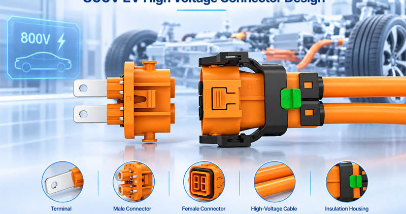
The development of 800V electric vehicle (EV) architectures is changing the requirements for automotive high-voltage interconnection systems. By increasing system voltage, EV manufacturers can reduce current for a given power level, potentially lowering resistive losses and enabling more efficient power distribution.
However, higher operating voltage also creates new challenges for connector design. Insulation coordination, electrical spacing, contact reliability, thermal management, mechanical protection, and high-voltage safety must all be considered together.
For connector manufacturers and automotive engineering teams, designing an 800V EV connector is not simply a matter of increasing the voltage rating of an existing 400V product. The entire connector system must be evaluated against its electrical, mechanical, thermal, and environmental operating conditions.
This article explores the key design challenges of 800V EV connectors and the engineering solutions that can help improve safety and long-term reliability.
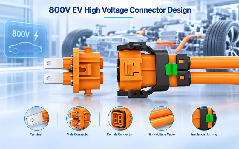
1.Why 800V EV Architectures Require Different Connector Design Considerations
An 800V EV platform uses a higher-voltage electrical architecture than conventional 400V systems. One important advantage is the ability to transmit the same electrical power at a lower current.
The relationship between electrical power, voltage, and current explains this advantage: electrical power equals voltage multiplied by current.
For example, under ideal DC conditions:
| Electrical Power | 400V System | 800V System |
|---|---|---|
| 100 kW | 250 A | 125 A |
| 150 kW | 375 A | 187.5 A |
| 200 kW | 500 A | 250 A |
At the same power level, doubling the voltage halves the current. Since resistive losses increase with the square of current, reducing current can significantly reduce conductor losses when resistance remains unchanged.
However, this does not mean that every connector in an 800V vehicle can simply be made smaller. Higher voltage increases insulation requirements, while actual connector current still depends on the application, power demand, conductor size, cooling conditions, and allowable temperature rise.
Engineers must therefore balance electrical performance with packaging constraints, safety requirements, and manufacturing feasibility.
It is also important to distinguish between an 800V vehicle electrical architecture and an EV charging connector. Vehicle-mounted high-voltage connectors, battery connections, inverter connections, and external charging couplers have different interfaces, operating conditions, and applicable standards. Their requirements should be evaluated separately.
2.Challenge One: High-Voltage Insulation and Electrical Safety
Insulation is one of the most important design considerations for 800V EV connectors.
As working voltage increases, the risk associated with electrical breakdown, surface tracking, and insulation degradation becomes more significant. Connector insulation must maintain adequate electrical separation between conductive components under the specified operating and environmental conditions.
Key design risks
- Insufficient insulation thickness
- Electrical breakdown between adjacent terminals
- Surface tracking caused by contamination or moisture
- Insulation degradation under elevated temperatures
- Reduced dielectric performance after environmental aging
- Electrical stress around sharp edges and geometric discontinuities
Engineering solutions
1.Select suitable insulation materials
Connector housing materials should be selected according to dielectric performance, temperature resistance, mechanical strength, moisture behavior, and long-term aging characteristics.
Engineering plastics such as PBT, PA, and PPS may be considered depending on the application. However, no material should be selected based on its polymer name alone. The specific grade, reinforcement, flame-retardant system, processing conditions, and tested properties all matter.
2.Optimize insulation wall thickness
The housing should provide sufficient solid insulation between conductive components. Engineers should consider dimensional tolerances, molding variation, mechanical stress, and material aging when defining wall thickness.
3.Reduce electrical stress concentrations
Sharp terminal edges, burrs, and poorly controlled geometric transitions can create localized electrical stress. Appropriate terminal geometry and manufacturing controls help reduce these risks.
4.Validate insulation performance
Electrical testing should verify that the connector maintains the required insulation performance under the defined test conditions, including after relevant environmental exposure where required.
The design should be evaluated against the actual voltage profile, including operating voltage, transient conditions, and applicable safety requirements.
3.Challenge Two: Creepage Distance and Clearance Distance
Creepage and clearance are two fundamental parameters in high-voltage connector insulation design.
Although they are related, they describe different electrical separation paths.
Clearance distance is the shortest distance through air between two conductive parts.
Creepage distance is the shortest distance along the surface of an insulating material between two conductive parts.
In an 800V connector, insufficient clearance may increase the risk of electrical discharge through air, while insufficient creepage distance may increase the risk of surface tracking under certain contamination and humidity conditions.
What Determines the Required Distances?
Creepage and clearance requirements cannot be determined by nominal voltage alone.
Relevant design parameters include:
- Working voltage and voltage waveform
- Impulse or transient overvoltage conditions
- Pollution degree
- Insulating material group and comparative tracking index (CTI)
- Altitude
- Insulation type and applicable safety requirements
- Manufacturing tolerances and connector geometry
IEC 60664-1 provides insulation coordination principles, including requirements and test methods for clearances, creepage distances, and solid insulation. Its 2025 consolidated edition incorporates Amendment 1 and covers equipment up to 1,500 V DC within its stated scope.
Engineering Solutions
Optimize internal terminal spacing
Terminal layouts should provide the required electrical separation without unnecessarily increasing connector dimensions.
Use insulating ribs and barriers
Molded ribs and internal barriers can extend the surface creepage path while maintaining a compact external housing.
Select materials with suitable tracking resistance
CTI is an important material property when evaluating surface tracking performance. Material selection should be based on the applicable insulation coordination requirements, not on a single CTI value in isolation.
Account for real manufacturing tolerances
The minimum insulation distance must remain compliant in the worst-case dimensional condition, including terminal position variation, housing deformation, and assembly tolerances.
A compact connector design should never compromise the required insulation distances.
4.Challenge Three: Contact Resistance and Thermal Management
Even when an 800V system reduces current for a given power level, connector contacts still generate heat during operation.
The main source of resistive heating at the contact interface is contact resistance. Heat generation increases with the square of current and is also affected by the resistance of the electrical path.
For example, if the contact resistance is 1 mΩ:
| Current | Contact Resistance | Resistive Heat |
|---|---|---|
| 100 A | 1 mΩ | 10 W |
| 150 A | 1 mΩ | 22.5 W |
| 200 A | 1 mΩ | 40 W |
| 250 A | 1 mΩ | 62.5 W |
These figures are simplified calculations for an individual resistance value under steady current. Actual connector temperature depends on heat distribution, conductor geometry, thermal conductivity, contact interface behavior, ambient temperature, and cooling conditions.
Why Does Contact Resistance Increase?
Potential causes include:
- Inadequate contact force
- Terminal deformation
- Surface oxidation or contamination
- Plating wear
- Poor terminal alignment
- Fretting caused by repeated micro-motion
- Inconsistent crimping or termination quality
Engineering Solutions
1.Optimize contact geometry
Contact design should provide stable contact force and sufficient effective contact area under specified operating conditions.
2.Select suitable contact materials and plating
Copper alloys are commonly considered for conductive terminals because of their electrical and mechanical properties. Contact plating should be selected according to current requirements, mating cycles, corrosion exposure, and long-term contact stability.
3.Control terminal manufacturing processes
Stamping, forming, plating, and assembly processes must be controlled to maintain consistent terminal dimensions and contact characteristics.
4.Conduct temperature rise testing
Temperature rise testing helps evaluate thermal behavior under defined current, ambient temperature, and installation conditions. Engineers should monitor critical contact regions and cable termination areas rather than relying only on the connector’s external surface temperature.
For high-current EV charging connectors, thermal management can involve more advanced approaches. Recent research has investigated heat-pipe-based thermal management for high-power charging connectors, illustrating how thermal design is becoming an increasingly important part of high-power interconnection systems.
5.Challenge Four: Partial Discharge and Insulation Degradation
Partial discharge is a localized electrical discharge that can occur within or around insulation under certain electrical stress conditions without immediately bridging the entire insulation gap.
It is particularly relevant when designing high-voltage insulation systems with small gaps, voids, material interfaces, or localized electric field concentrations.
Potential Causes
- Air voids inside molded insulation
- Poor material bonding
- Sharp conductive edges
- Insufficient insulation design margins
- Material defects or contamination
- Inadequate control of molding and assembly processes
Repeated electrical stress may contribute to insulation degradation over time, depending on the material system and operating conditions.
Engineering Solutions
Improve insulation material and molding quality
Material drying, molding parameters, venting, and process consistency should be controlled to reduce defects that could affect insulation integrity.
Optimize electric field distribution
Terminal geometry should avoid unnecessary sharp edges and localized stress concentrations. Electrical field simulation can help identify high-field regions before tooling is finalized.
Evaluate insulation under relevant electrical conditions
Where required by the product specification or applicable validation plan, engineers should consider partial-discharge testing or other suitable insulation diagnostic methods.
Partial-discharge testing should not be assumed to be a universal requirement for every automotive connector. Its applicability and acceptance criteria need to be defined based on the insulation system and project requirements.
6.Challenge Five: Material Selection Under High-Voltage and High-Temperature Conditions
An 800V EV connector must maintain its electrical and mechanical properties throughout its expected operating life.
Material selection affects insulation performance, thermal stability, mechanical strength, chemical resistance, and dimensional consistency.
Housing Material Considerations
| Material | Potential Advantages | Design Considerations |
|---|---|---|
| PBT | Dimensional stability and electrical insulation properties | Grade-specific temperature and chemical resistance |
| PA | Mechanical strength and established molding applications | Moisture absorption and dimensional variation |
| PPS | High-temperature performance and dimensional stability | Grade selection, brittleness, and processing control |
These materials are examples rather than a universal ranking. The correct choice depends on the application, required temperature range, mechanical loading, environmental exposure, and validation results.
Terminal Material Considerations
Terminal materials must balance:
- Electrical conductivity
- Mechanical strength
- Spring characteristics
- Stress relaxation resistance
- Corrosion resistance
- Formability and manufacturability
Copper alloys are commonly used in electrical terminal systems. The specific alloy and temper should be selected according to contact force, current capacity, geometry, and manufacturing requirements.
Plating Considerations
Tin and silver plating may be considered for different automotive electrical applications, while gold plating is often used where stable low-level contact performance is important.
The selection should account for:
- Contact resistance requirements
- Operating current
- Temperature exposure
- Corrosion environment
- Mating and unmating cycles
- Fretting and wear behavior
- Plating thickness and underplating
The goal is not simply to choose a material with the highest specification. It is to establish a material system that performs reliably under actual operating conditions.
7.Challenge Six: High-Voltage Interlock and Connector Safety
High-voltage safety is another essential part of EV connector design.
Many automotive high-voltage systems use a High Voltage Interlock Loop (HVIL) to monitor the connection status of high-voltage components.
The HVIL circuit is generally designed to detect the opening or disconnection of a monitored high-voltage connection and trigger the vehicle’s safety response according to its electrical architecture.
Why Is HVIL Important?
During service, maintenance, or unintended connector separation, high-voltage circuits must be managed to reduce the risk of electric shock and electrical arcing.
An HVIL system can help ensure that the vehicle control system receives an appropriate signal before a high-voltage connection is physically separated.
Engineering Solutions
1.Design appropriate contact sequencing
The interlock contact arrangement should be coordinated with the mechanical mating and unmating sequence.
2.Maintain reliable interlock contact performance
The low-voltage interlock circuit must maintain reliable electrical continuity under vibration, temperature changes, and repeated connection cycles.
3.Coordinate connector and vehicle-level safety logic
The connector design alone does not define the entire safety response. HVIL behavior must be evaluated together with the vehicle’s contactors, control strategy, and electrical architecture.
4.Validate the mechanical and electrical sequence
Testing should confirm that the interlock signal changes as intended during connector operation and under relevant fault conditions.
ISO 20076:2019 covers test methods and performance requirements for certain voltage Class B connectors used in road vehicles. It also highlights the importance of evaluating connector-related safety features such as HVIL in the context of the connector and vehicle electrical architecture.
8.Challenge Seven: Mechanical Durability, Vibration, and Environmental Protection
An 800V connector must maintain electrical insulation and contact stability throughout the vehicle’s operating life.
Automotive connectors are exposed to vibration, mechanical shock, thermal cycling, humidity, water, dust, and chemical substances, depending on their installation location.
These conditions can affect both mechanical structures and electrical contact interfaces.
Common Mechanical and Environmental Risks
- Terminal displacement or back-out
- Housing cracks or deformation
- Locking mechanism failure
- Seal damage
- Water or dust ingress
- Contact wear and fretting corrosion
- Loss of contact force after aging
- Cable movement transferring stress to the connector interface
Engineering Solutions
Strengthen terminal retention
Terminal locking structures should prevent unintended movement while maintaining consistent assembly quality.
Optimize connector locking mechanisms
Primary locking and secondary locking features should be designed to resist unintended separation under specified mechanical conditions.
Improve sealing structures
Seals, gaskets, and interface geometries should be selected according to the required IP protection level and installation environment.
Control cable routing and strain relief
Cable weight, bend radius, routing, and support points should be considered to reduce mechanical loads transferred to the connector.
Validate environmental durability
Depending on the application, testing may include vibration, mechanical shock, thermal cycling, humidity, ingress protection, and corrosion exposure.
The test plan should reflect the connector’s actual installation location and OEM requirements rather than applying the same test conditions to every product.
9.Challenge Eight: Compact Packaging and Manufacturing Consistency
EV manufacturers continue to pursue smaller, lighter, and more integrated electrical systems.
However, compact connector packaging can conflict with the larger insulation distances and stronger mechanical structures required by high-voltage applications.
This creates a design challenge: how can engineers maintain safety and reliability without unnecessarily increasing connector size?
Engineering Solutions
Use optimized terminal arrangements
A carefully designed terminal layout can improve electrical separation and packaging efficiency.
Integrate insulation features into the housing
Internal ribs, barriers, and optimized cavity geometry can help meet insulation requirements without excessively increasing the overall connector footprint.
Apply simulation during early design
Electrical field analysis, thermal simulation, and mechanical analysis can help identify design risks before prototype tooling.
Control critical manufacturing dimensions
Even a well-designed connector can fail to achieve its intended performance if terminal position, housing dimensions, or assembly tolerances are inconsistent.
A practical design process should therefore connect engineering analysis with tooling design, process capability, and inspection planning.
10.Recommended Validation Tests for 800V EV Connectors
A robust validation plan should evaluate electrical, mechanical, thermal, and environmental performance.
The exact tests and acceptance criteria depend on the connector’s application, voltage class, OEM specifications, and applicable standards.
| Test Category | Typical Evaluation | Design Objective |
|---|---|---|
| Dielectric withstand | Electrical withstand under specified test conditions | Verify insulation strength |
| Insulation resistance | Resistance between isolated conductive parts | Evaluate electrical isolation |
| Contact resistance | Resistance across mating contacts | Verify electrical contact stability |
| Temperature rise | Temperature under defined current and ambient conditions | Evaluate thermal performance |
| Terminal retention | Resistance to terminal displacement | Verify mechanical retention |
| Vibration | Electrical and mechanical behavior during vibration | Evaluate durability |
| Thermal cycling | Performance after repeated temperature changes | Assess material and interface stability |
| Humidity exposure | Insulation and material behavior under moisture exposure | Evaluate environmental durability |
| Ingress protection | Resistance to water and dust ingress | Verify sealing performance |
| HVIL function | Interlock continuity and switching sequence | Verify safety-related interface behavior |
Relevant Standards and References
The following standards and technical references may be relevant, depending on the product and application:
- ISO 20076:2019 – Test methods and performance requirements for specified voltage Class B road-vehicle connectors.
- IEC 60664-1:2020+A1:2025 – Insulation coordination principles, requirements, and tests.
- SAE USCAR-12 – Wiring component design guidelines, including high-voltage application considerations. Confirm the applicable revision and customer requirements before use.
- OEM-specific specifications – Additional electrical, mechanical, environmental, and safety requirements.
These documents have different scopes. They should not be treated as interchangeable or assumed to apply to every EV connector type. In particular, ISO 20076 excludes vehicle charging inlets from its stated scope.
11.From Prototype to Mass Production: What Connector Manufacturers Must Control
Successful 800V connector development requires more than a technically acceptable prototype.
The design must also be repeatable in mass production.
Important manufacturing controls include:
Terminal stamping and forming
Critical dimensions, spring geometry, burr direction, and forming consistency should be controlled to maintain contact performance.
Contact plating
Plating thickness, surface quality, adhesion, and process consistency should be verified according to the product specification.
Plastic injection molding
Material drying, molding temperature, pressure, cooling, and dimensional stability can influence insulation performance and housing quality.
Terminal assembly
Insertion position, retention features, and assembly completeness should be checked using suitable inspection methods.
Electrical testing
Electrical inspection should cover the characteristics defined by the control plan and customer specification.
Traceability
Production batches, material information, inspection results, and engineering revisions should be managed systematically.
For OEM projects, the transition from prototype to mass production should include design review, process risk assessment, validation, production readiness review, and the required customer approval documentation.
A structured quality approach helps ensure that the connector performs consistently beyond the initial sample stage.
12.Final Thoughts: Designing Reliable Connectors for 800V EV Platforms
The transition to 800V EV architectures creates opportunities for more efficient vehicle power distribution, but it also raises the technical requirements for high-voltage interconnection systems.
Connector engineers must balance insulation coordination, creepage and clearance distances, contact resistance, thermal performance, material selection, mechanical durability, and electrical safety.
No single design feature can guarantee connector reliability. A successful 800V EV connector depends on the combined performance of its terminal system, insulating housing, sealing structure, locking mechanism, cable interface, and manufacturing process.
For automotive OEMs and Tier 1 suppliers, involving connector manufacturers early in the development process can help identify design risks, evaluate material options, and establish a more effective validation plan.
As EV platforms continue to evolve, high-voltage connector design will remain an important part of vehicle electrical system reliability.
FAQ
What is an 800V EV connector?
An 800V EV connector is a high-voltage electrical connector designed for use in electric vehicle systems operating within an 800V-class electrical architecture. It may be used in battery connections, power distribution, inverter interfaces, and other high-voltage applications, depending on its design and rating.
Can a 400V EV connector be used in an 800V system?
Not automatically. A connector designed for a 400V application should not be assumed suitable for an 800V system. Its rated voltage, insulation coordination, dielectric performance, creepage and clearance distances, and other relevant requirements must be verified against the intended application.
Why are creepage and clearance important in 800V connectors?
Creepage and clearance provide electrical separation between conductive parts. Adequate distances help reduce the risk of electrical breakdown and surface tracking. Their required values depend on working voltage, transient conditions, pollution degree, insulation material, altitude, and applicable standards.
Does an 800V EV system always require a larger connector?
Not necessarily. Higher voltage may require greater electrical separation, but optimized terminal arrangements, insulating ribs, suitable materials, and compact housing structures can help manage packaging constraints. The final dimensions depend on current capacity, insulation requirements, mechanical loads, and the application.
How does contact resistance affect 800V EV connector performance?
Contact resistance generates heat in proportion to current squared and resistance. Excessive or unstable contact resistance can cause localized heating, accelerate material degradation, and affect electrical reliability. Stable contact force, suitable plating, precision manufacturing, and temperature rise testing are important controls.
What is the role of HVIL in an 800V EV connector?
A High Voltage Interlock Loop monitors the connection status of high-voltage components and provides a signal to the vehicle’s safety control system. Its operation must be coordinated with the vehicle’s electrical architecture and safety response strategy.
What tests are important for 800V EV connectors?
Typical evaluations include dielectric withstand, insulation resistance, contact resistance, temperature rise, terminal retention, vibration, thermal cycling, humidity, and ingress protection testing. The final validation plan should follow the application requirements and relevant OEM specifications.
Develop High-Voltage Connector Solutions with FPIC
Developing connectors for high-voltage automotive applications requires careful attention to electrical performance, insulation design, mechanical reliability, and manufacturing consistency.
FPIC provides automotive connector manufacturing and customized development support, with a focus on precision production and quality control.
For OEM and Tier 1 projects, early technical discussions can help clarify connector specifications, material requirements, manufacturing considerations, and validation expectations.
Contact FPIC to discuss your automotive connector development requirements.
Resources
- IEC 60664-1:2020+A1:2025 – Insulation CoordinationOfficial IEC reference covering insulation coordination, creepage distances, clearances, solid insulation, and electrical testing.
- ISO 20076:2019 – Test Methods and Performance Requirements for Voltage Class B ConnectorsISO reference for specified high-voltage connectors used in road vehicle electrical systems.
- SAE USCAR-12 – Wiring Component Design GuidelinesSAE design guideline covering wiring component functional requirements, including high-voltage applications. Check the applicable revision.
- Thermal Management Optimization for High-Power EV Charging ConnectorsResearch paper examining a heat-pipe-based thermal management approach for high-power EV charging connectors.
- Eight EV Challenges of Converting High Voltage to SELVTechnical discussion of high-voltage EV design considerations, including creepage, clearance, and insulation constraints.